POO-WC75Bluetooth LE Module
Mitsumi Electric Co., Ltd.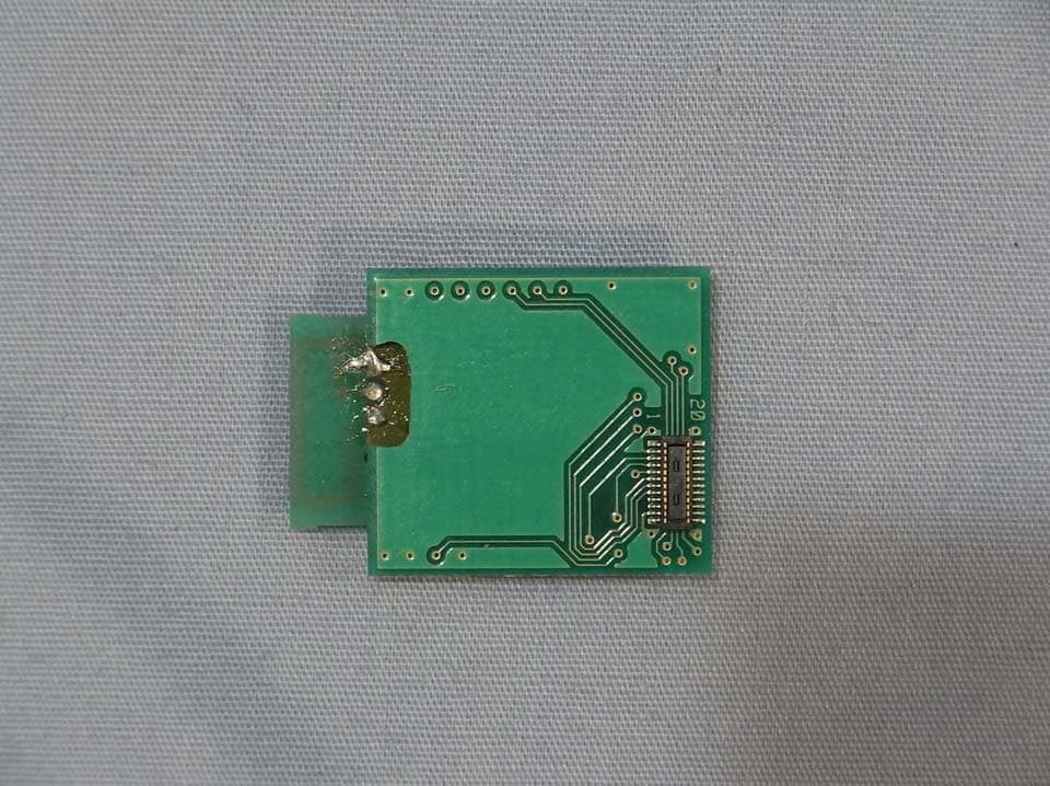
Click to zoom
Application Details
- Equipment Class
- DTS - Digital Transmission System
- Date of Grant
- Jan 07, 2014
- Application Purpose
- Original Equipment
- Date of Application
- Jan 07, 2014
- Equipment Note
- Bluetooth LE Module
- Frequency Range
- 2402.00000000 - 2480.00000000
- Company
- Mitsumi Electric Co., Ltd.
- Country
- Japan
Documents & Files
Document Text
Text extracted from the exhibit documents filed with the FCC. Open a document above to read the original.
Users Manual
Page 1 of 7 WML-C75_User_Manual 1. DECEMBER. 2013 COMMERCIAL IN CONFIDENCE This material may not in whole or part be copied, stored electronically or communicated to third parties without MITSUMI ELECTRIC CO., LTD’s prior agreement in writing. WML- C75 User Manual The purpose of this manual is to explain correct way how to integrate module WML-C75 to the end product. It includes procedures that shall assist you to avoid unforeseen problems. This manual presents information that shows how module and OEM product, where module integrated, complies with regulations in certain regions. Any modifications, not expressly approved by the manufacturer could void the authority to operate in these regions. Content 1. General 2. Description 3. European Community Declaration of Conformity with Regard to the R&TTE Directive 1999/5/EC 4. FCC Regulatory Information 1. General This Bluetooth radio module has to be installed and used in accordance with the technical description/installation instructions provided by the manufacturer. This Bluetooth radio module is intended to be placed on the market in all States, where the Bluetooth™ technology and the used frequency band is released. For detail information concerning type approval of this module (e.g. where this module is already pre-approved) please contact the manufacturer. The system may only be implemented in the configuration that was authorized. Note that any changes or modifications to this equipment not expressly approved by the manufacturer could void the user’s authority to operate this equipment. Page 2 of 7 WML-C75_User_Manual 1. DECEMBER. 2013 COMMERCIAL IN CONFIDENCE This material may not in whole or part be copied, stored electronically or communicated to third parties without MITSUMI ELECTRIC CO., LTD’s prior agreement in writing. 2.DESCRIPTION. 2.1 Model Number WML-C75 2.2 Hardware: Version 1 This document describes the reference design for application as follows. 2.3 FEATURES Bluetooth Ver4.0 Low Energy Single Mode Host Interface:UART Frequency: 2402-2480MHz (World Wide) RF Channel band: 2MHz RF Channel number: 40ch Data Rate: 1Mbps Output Power: 8.2dBm(MAX) Sensitivity: -84dBm Supply Voltage: 1.8V-3.6V Current Consumption Tx: 15mA(at 0dBm), Rx: 17mA, Sleep: 0.6uA Operating temperature: -30 to +85 degree C Module size: 19.0mm x 12.5mm x 2.3mm 2.4 APPLICATIONS Healthcare products, digital cameras, PC peripherals, PDA. 2.5 ARCHITECTONICS WML-C75 has Bluetooth chip and Crystal inside. UART interface is used for customer’s application. Following figure shows Software Stack for WML-C75 and customer’s application as example. Page 3 of 7 WML-C75_User_Manual 1. DECEMBER. 2013 COMMERCIAL IN CONFIDENCE This material may not in whole or part be copied, stored electronically or communicated to third parties without MITSUMI ELECTRIC CO., LTD’s prior agreement in writing. 2.6 SOFTWARE LAYERS 2.7 SOFTWARE SUPPORT Non: Mitsumi provides HW only (Software developed by customer) Standard: SIG- compliant Profiles (such as Proximity) Full Custom: SIG-compliant Profiles + User specification External Control:Standard, Full Custom + additional external I/F(external microprocessor) Page 4 of 7 WML-C75_User_Manual 1. DECEMBER. 2013 COMMERCIAL IN CONFIDENCE This material may not in whole or part be copied, stored electronically or communicated to third parties without MITSUMI ELECTRIC CO., LTD’s prior agreement in writing. 2.8 DIMENSIONS Page 5 of 7 WML-C75_User_Manual 1. DECEMBER. 2013 COMMERCIAL IN CONFIDENCE This material may not in whole or part be copied, stored electronically or communicated to third parties without MITSUMI ELECTRIC CO., LTD’s prior agreement in writing. 3. European Community Declaration of Conformity with Regard to the R&TTE Directive 1999/5/EC Hereby,MITSUMI declares that The Mitsumi module WML-C75 complies with the following directive and standards: Directive 1999/5/EG (R&TTE Directive): EN 300 328 V1.8.1 (2012-04), Electromagnetic compatibility and Radio spectrum Matters (ERM); Wideband transmission systems; Data transmission equipment operating in the 2,4 GHz ISM band and using wide band modulation techniques; Harmonized EN covering essential requirements under article 3.2 of the R&TTE Directive We hereby declare that the human exposure of the Mitsumi module WML-C75 is below the SAR limits specified in the EU recommendation 1999/519/EC (the applicable limits are specified in table 1 with 2W/kg). The technical documentation as required by the Conformity Assessment procedure is kept at the following address : 2-11-2, TSURUMAKI, TAMA-SHI, TOKYO, 206-8567 JAPAN. MITSUMI ELECTRIC CO.,LTD. ENGINEERING DEPTMENT RF MODULE BUSINESS DIVISION TEL:+81-42-310-5691 FAX:+81-42-310-5582 Labelling CE conformity marking for product. OEM product / application, where this radio module is integrated/ installed in , has to be labelled in accordance to R&TTE directive, Article 12. An auxiliary label is included in the packaging to the radio module, which can be used for that purpose and has to be permanently affixed to the OEM product/ application, otherwise OEM product must be approved separately. Regulatory information on the OEM devise should contain labelling that: Approved in accordance to R&TTE directive transmitter module marked by CE, manufactured by MITSUMI incorporated to OEM product. Page 6 of 7 WML-C75_User_Manual 1. DECEMBER. 2013 COMMERCIAL IN CONFIDENCE This material may not in whole or part be copied, stored electronically or communicated to third parties without MITSUMI ELECTRIC CO., LTD’s prior agreement in writing. 4. FCC Regulatory Information The Federal Communication Commission Radio Frequency Interference Statement includes the following paragraph: This equipment has been tested and found to comply with the limits pursuant to Part 15 of the FCC Rules. These limits are designed to provide reasonable protection against harmful interference in a residential installation. This equipment generates, uses and radiates radio…
Text truncated - open the document above for the full version.
External Photos
MITSUMI ELECTRIC CO., LTD. FCC ID: POO-WC75 External photos MITSUMI ELECTRIC CO., LTD. FCC ID: POO-WC75
ID Label/Location Info
WML‐C75 Logo Layout PWB:printed wiring boardSilk‐screening Shield CaseLaser printing
Internal Photos
MITSUMI ELECTRIC CO., LTD. FCC ID: POO-WC75 Internal photos MITSUMI ELECTRIC CO., LTD. FCC ID: POO-WC75
Test Report
Page 2 of 37 TÜV SÜD Zacta Ltd. Report number: Z071C-13470 Test Report Rev.FCC-C2.0 FCC ID: POO-WC75 Table of contents Page 1. Summary of Test ................................................................................................................. 4 1.1 Purpose of test ....................................................................................................................................... 4 1.2 Standards ............................................................................................................................................... 4 1.3 List of applied test to the EUT .............................................................................................................. 4 1.4 Modification to the EUT by laboratory ................................................................................................. 4 2. Equipment Under Test ........................................................................................................ 5 2.1 General Description of equipment ....................................................................................................... 5 2.2 EUT information ..................................................................................................................................... 5 2.3 Variation of the family model(s) ............................................................................................................ 6 2.4 Operating channels and frequencies .................................................................................................. 6 2.5 Operating mode ..................................................................................................................................... 6 2.6 Operating mode ..................................................................................................................................... 7 3. Configuration of equipment ............................................................................................... 8 3.1 Equipment(s) used................................................................................................................................. 8 3.2 Cable(s) used ......................................................................................................................................... 8 3.3 System configuration ............................................................................................................................ 8 4. 6dB Bandwidth .................................................................................................................... 9 4.1 Measurement procedure ....................................................................................................................... 9 4.2 Limit ......................................................................................................................................................... 9 4.3 Measurement result ............................................................................................................................... 9 4.4 Trace data ............................................................................................................................................. 10 5. Maximum Peak Output Power .......................................................................................... 11 5.1 Measurement procedure ...................................................................................................................... 11 5.2 Limit ........................................................................................................................................................ 11 5.3 Measurement result ............................................................................................................................. 12 5.4 Trace data ............................................................................................................................................. 13 6. Band Edge Compliance of RF Conducted Emissions .................................................... 16 6.1 Measurement procedure ..................................................................................................................... 16 6.2 Limit ....................................................................................................................................................... 16 6.3 Measurement result ............................................................................................................................. 16 6.4 Trace data ............................................................................................................................................. 17 7. Spurious emissions - Conducted - .................................................................................. 18 7.1 Measurement procedure ..................................................................................................................... 18 7.2 Limit ....................................................................................................................................................... 18 7.3 Measurement result ............................................................................................................................. 18 7.4 Trace data ............................................................................................................................................. 19 8. Spurious Emissions - Radiated -...................................................................................... 22 8.1 Measurement procedure ..................................................................................................................... 22 8.2 Calculation method.............................................................................................................................. 23 8.3 Limit ............................................................................................…
Text truncated - open the document above for the full version.
Test Setup Photos
MITSUMI ELECTRIC CO., LTD. FCC ID: POO-WC75 System configuration (RF Conducted test) Transmitter Radiated Spurious Emissions (RF Radiated test) MITSUMI ELECTRIC CO., LTD. FCC ID: POO-WC75 X-axis Y-axis Z-axis Note: X-axis generates the maximum emission. MITSUMI ELECTRIC CO., LTD. FCC ID: POO-WC75 Conducted Emission at mains port The photographs show maximized emission configuration.
Contact Information
Applicant
Katsunori Kobari(Mr.)
Test Firm
TUV SUD Japan Ltd. Yonezawa Testing CenterHiroaki Suzuki
[email protected]81-238-40-1681
Technical Specifications
| # | Rule Parts | Frequency Range | Power Output |
|---|---|---|---|
| 1 | 15C | 2.40 GHz - 2.48 GHz | 6.58 mW |
Other Applications from Mitsumi Electric Co., Ltd.
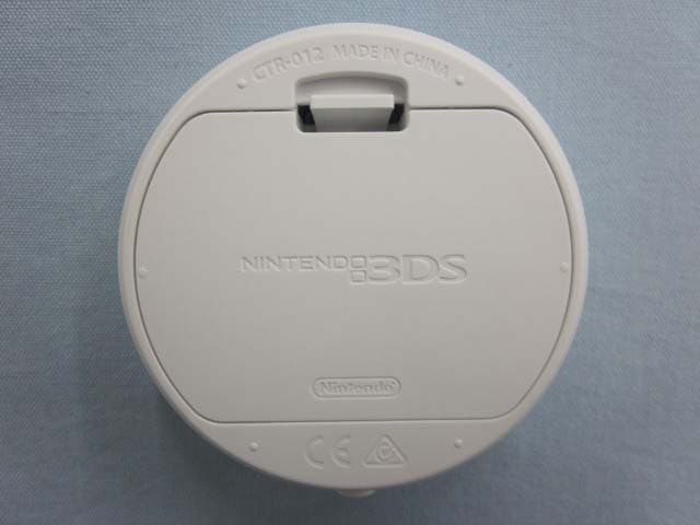
POOCTR012
Feb 07, 2015RFID Product
Equipment Class
DXX - Part 15 Low Power Communication Device Transmitter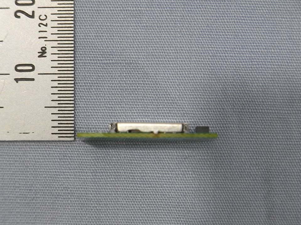
POO-WC69
Apr 24, 2013Bluetooth LE Module
Equipment Class
DTS - Digital Transmission System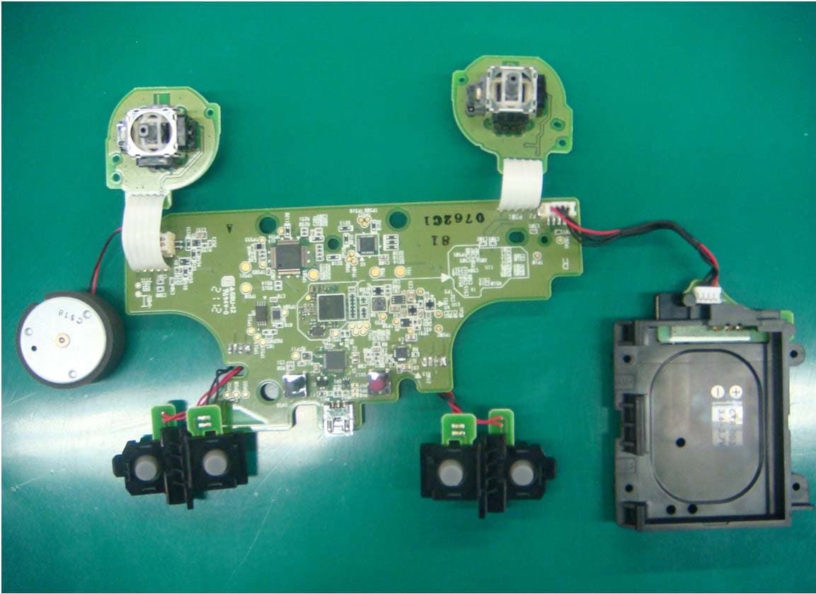
POO-R237999
Jul 10, 2012Remote Controller
Equipment Class
DSS - Part 15 Spread Spectrum TransmitterPOO-DR237973
Mar 24, 2012Remote Controller
Equipment Class
DSS - Part 15 Spread Spectrum Transmitter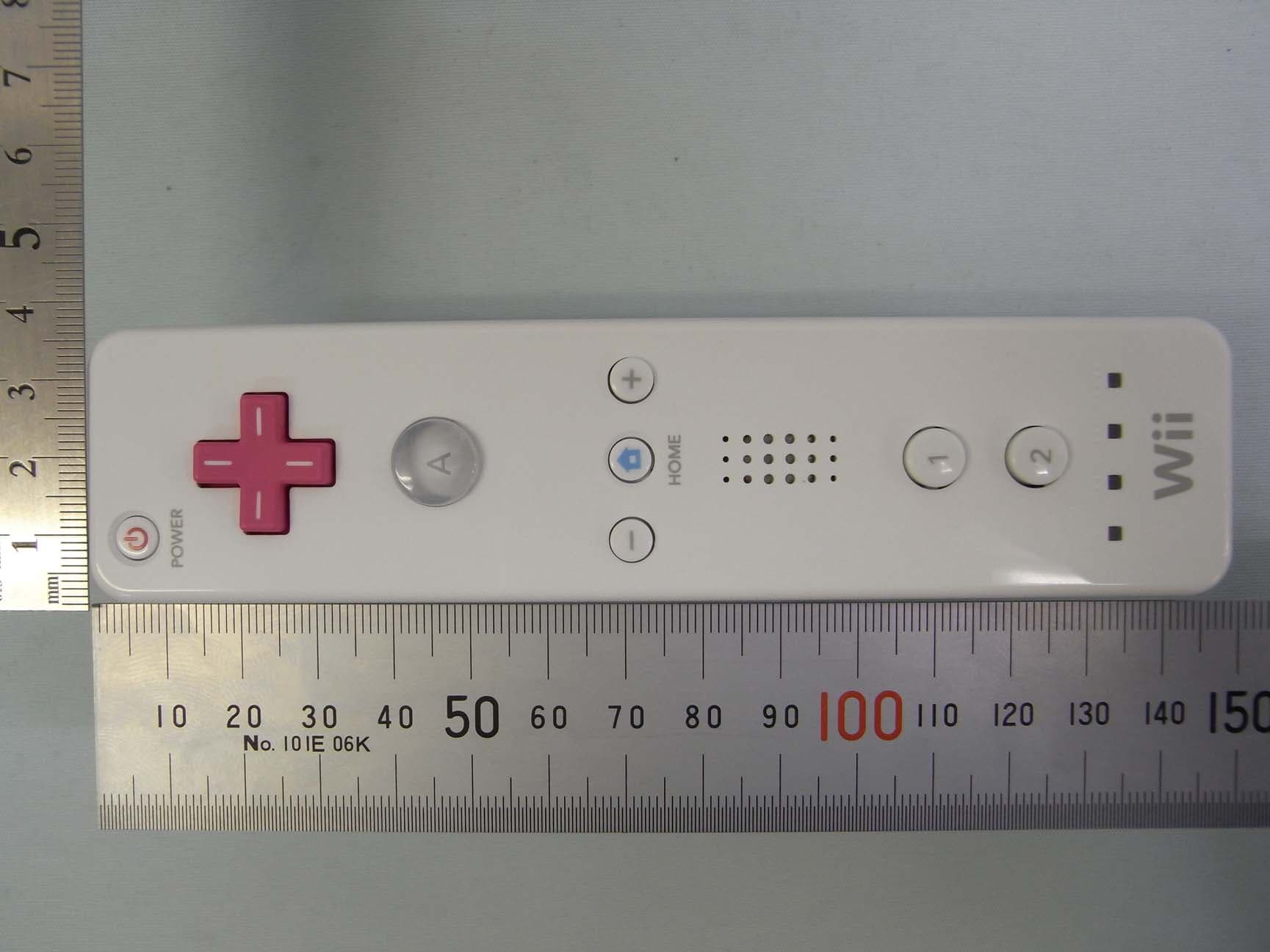
POO-WC62
May 30, 2010Wii Remote Controller
Equipment Class
DSS - Part 15 Spread Spectrum Transmitter