PPQ-AWOXMII2Mozart II
LITE-ON TECHNOLOGY CORP.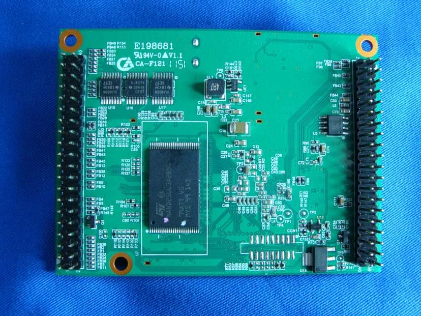
Click to zoom
Application Details
- Equipment Class
- DTS - Digital Transmission System
- Date of Grant
- Jan 29, 2012
- Application Purpose
- Original Equipment
- Date of Application
- Jan 19, 2012
- Equipment Note
- Mozart II
- Frequency Range
- 2422.00000000 - 2452.00000000
- Company
- LITE-ON TECHNOLOGY CORP.
- Country
- Taiwan
Documents & Files
Document Text
Text extracted from the exhibit documents filed with the FCC. Open a document above to read the original.
Users Manual
AWOX, S.A. 93 Place Pierre Duhem 34000 MONTPELLIER, France Tel: +33 4 67 47 10 00, Fax: +33 4 67 47 10 15 www.awox.com [email protected] T-0000-0005-V2.1: Digital Mozart II Module Page: 1 / 4 Technical Note Digital Mozart II Module 1 Introduction The original design of Mozart II includes everything an audio system designer needs in terms of digital to analog conversion and analog signal management ready to feed to analog amplifiers or outputs. Basically, ADC,DAC, FM tuner and all volume control and equalization are built-in. Some applications do not make use of analog output (for instance, connecting the module to some digital audio processor does not require analog) or will make use of their own converters for feature or cost reasons. Therefore, Mozart II can be delivered as “digital only”, which means only the digital stream is provided to the outside world. The general considerations on Mozart II use can be found in the master documentation for the full- fledged module. This document only describes the changes between the two versions. It is therefore recommended to read the full-fledged version documentation before this one. A reference schematic for Mozart II Digital implementation is provided. 2 Clocking As in any digital audio system, clocking is an important point. Mozart II is using I2S 3-Wire protocol by default and needs a Master Clock frequency to be provided on I2S_REF pin and equal to 11.2896MHz or 12.288MHz. The internal module dividers provide the according I2S_LRCK, I2S_BCLK and the I2S_DATA is latched conforming to I2S 16 bits per channel standard. Awox may carry on particular studies upon customer request for specific unsupported sound peripherals. 3 DACs and amplifiers 3.1 SUPPORTED DACS The reference DAC for use with Mozart II Digital is Wolfson Micro WM8711. This low-cost DAC allows simple and easy construction of analog products using Mozart II Digital. It is the one that is used on the Analog variant of the module and is therefore not part of the reference schematic for sake of explanation; Mozart II Digital makes little sense versus the analog variant if the same peripherals are used; the goal is to be able to use feature-rich peripherals for mid to high-end devices. Please contact AwoX for more information. 3.2 AMPLIFIERS The reference digital amplifier, Class-D, for use with Mozart II Digital is the Cirrus Logic CS4525. It has provision for analog parts without adding external circuitry while still giving the benefit of the low- cost and simplicity of Mozart II Digital. T-0000-0005-V2.1: Digital Mozart II Module T-0000-0005-V2.1: Digital Mozart II Module Page: 2 / 4 4 Other Peripherals 4.1 S/PDIF The optical and coaxial outputs for S/PDIF are driven by a Cirrus Logic CS8406 S/PDIF encoder. Software re-sampling is used for non-native frequencies. The Quartet II reference schematic includes this part configured to drive an optical transmitter. To support coaxial SPDIF output, please contact AwoX for more information. 4.2 FM TUNER The reference tuner for use with Mozart II Digital is the Silicon Labs Si4704. The tuner has analog outputs, which means that its use on a daughterboard requires proper analog signal handling. The part is the same that is used on the analog variant of Mozart. 5 Daughterboard Schematic Description Front Panel, iPod , and Rear Panel Interface are identical to the digital version (with the exception of the Line Out replaced by Line In for demonstration purposes, but this input is directly managed by the amplifier used). Therefore, the description only highlights the Main Board which is quite simple. 5.1 AUDIO AMP SECTION (PAGE 1) The amplifier U4 and the module use external I2S clocking, providing the main frequency from crystal Y2. 5.2 FM TUNER & INTERCONNECT (PAGE 2) The FM tuner requires the use of a band-pass filter for proper FM reception. It uses its own external clock (Y3). Note that the interrupt line to the processor is shared and therefore open-drain, J20 is the connection to interface board. 5.3 5.3 POWER & CONNECTORS (PAGE 3) Strictly identical to analog version. AWOX, S.A. 93 Place Pierre Duhem 34000 MONTPELLIER, France Tel: +33 4 67 47 10 00, Fax: +33 4 67 47 10 15 www.awox.com [email protected] T-0000-0004-V2.1: Using Mozart II Page: 1 / 24 Technical Note Using Mozart II 1 Introduction to Mozart II Module HARDWARE FEATURES • R aLink RT3050/RT3052 system-on-chip • Memory - 32 MB 133 MHZ SDRAM (64 MB optional) - 32 MB NAND flash memory for system • FM Tuner • Audio - Stereo output (L/R RCA, daughterboard*) w/ headphones and line level - Stereo input (L/R RCA, daughterboard*) - I2S output, 16bits stereo - SPDIF output (Optical/RCA, daughterboard*) • Storage - USB 2.0 host (daughterboard*) • Network - 10/100Mb Ethernet MAC & PHY - Onboard Wireless LAN 802.11b/g/n - Encryption support: 40- and 128- bit WEP, WPA, CCX, TKIP & AES - WPS 2.0 security • Interface - Control LCD screen via SPI; supports monochrome and color TFT - Support for keyboard, up to 16 keys and one rotary encoder - Infrared decoder function for RC5 & NEC - Adjustable analog output within 0 ~ 3,3V range - External FM antenna (mini jack, daughterboard*) • Clock - Alarm, wake-up, snooze and sleep features • Power Supply required - 3.3V for main activity • Dimensions - 80 x 60 x 17 mm S OFTWARE FEATURES • S tored in NAND flash memory, fully upgradable via the Internet • Audio decoders - MP3 - WMA - WAV - AAC-LC - Real • AwoX streaming engine - HTTP - MMS • I nternet Radio Directory - vTuner Internet - baracoda • Digital Media Player (compliant with DLNA 1.5 guidelines) • Digital Media Renderer (compliant with DLNA 1.5 guidelines) • Linux Kernel 2.6.21 • Linux Drivers - Monochrome 128x64 LCD and QVGA TFT - Keyboard/keypad input - Wi-Fi Interface - FM tuner with optional RDS - Full-speed USB 2.0 host - Ethernet - SPDIF transmitter - Wi-Fi STA and AP 2 Introduction to Mozart II Module AwoX S.A. has developed and is manufacturing an electronic module, codenamed “Mozart II”…
Text truncated - open the document above for the full version.
Attestation Statements
LITE-ON Technology Corp. FCC ID.: PPQ-AWOXMII2 4F, No.90, Chien 1 Rd., Chung-Ho, Taipei Hsien 235, Taiwan.Tel : 886-2-2222-6181 Federal Communications Commission Dec. 30, 2011 Authorization and Evaluation Division ATTESTATION FCC ID: PPQ-AWOXMII2 Product: Mozart II Model: AWOXMII2A64, AWOXMII2D64 We don't provide any controls or software to allow operation outside the USA frequency band when we sell this product in USA. Sincerely, ---------------------------------------------------- TC Wu / Director LITE-ON Technology Corp.
Cover Letter(s)
RF_734_00, Issue 1 Modular Approval Request FCC (per DA 00-1407) FCC ID: PPQ-AWOXMII2 Items to be covered Answer from applicant 1. The modular transmitter must have its own RF shielding. Please review external photos. 2. The modular transmitter must have buffered modulation/data inputs (if such inputs are provided) to ensure that the module will comply with Part 15 requirements under conditions of excessive data rates or over-modulation. The buffered integrated in chip RT3052. 3. The modular transmitter must have its own power supply regulation. There are regulators in front of these chips; the part number of this regulator is SY8009AAAC. 4. The modular transmitter must comply with the antenna requirements of Section 15.203 and 15.204(c). The antenna must either be permanently attached or employ a “unique” antenna coupler (at all connections between the module and the antenna, including the cable).. Please review external photos or test report. 5. The modular transmitter must be tested in a stand-alone configuration, i.e., the module must not be inside another device during testing. This is intended to demonstrate that the module is capable of complying with Part 15 emission limits regardless of the device into which it is eventually installed. Please review test setup photos. 6. The modular transmitter must be labeled with its own FCC ID number, and, if the FCC ID is not visible when the module is installed inside another device, then the outside of the device into which the module is installed must also display a label referring to the enclosed module. This exterior label can use wording such as the following: “Contains Transmitter Module FCC ID: XYZMODEL1” or “Contains FCC ID: XYZMODEL1.” Any similar wording that expresses the same meaning may be used. The Grantee may either provide such a label, an example of which must be included in the application for equipment authorization, or, must provide adequate instructions along with the module which explain this requirement. In the latter case, a copy of these instructions must be included in the application for equipment authorization. Please review label sample. 7. The modular transmitter must comply with any specific rule or operating requirements applicable to the transmitter and the manufacturer must provide adequate instructions along with the module to explain any such requirements. A copy of these instructions must be included in the application for equipment authorization. For example, there are very strict operational and timing requirements that must be met before a transmitter is authorized for operation under Section 15.231. For instance, data transmission is prohibited, except for operation under Section 15.231(e), in which case there are separate field strength level and timing requirements. Compliance with these requirements must be assured. The EUT is compliant with all applicable FCC rules. Detail instructions for maintaining compliance are given in the Users Manual. 8. The modular transmitter must comply with any applicable RF exposure requirements. For example, FCC Rules in Sections 2.1091, 2.1093 and specific Sections of Part 15, including 15.319(i), 15.407(f), 15.253(f) and 15.255(g), require that Unlicensed PCS, UNII and millimeter wave devices perform routine environmental evaluation for RF Exposure to demonstrate compliance. In addition, spread spectrum transmitters operating under Section 15.247 are required to address RF Exposure compliance in accordance with Section 15.247(b)(4). Modular transmitters approved under other Sections of Part 15, when necessary, may also need to address certain RF Exposure concerns, typically by providing specific installation and operating instructions for users, installers and other interested parties to ensure compliance. The EUT is compliant with all applicable RF exposure requirements. RF Exposure is addressed in the RF exposure exhibition. Note: If compliance with one or more of the numbered requirements, listed above, cannot be demonstrated, it may be possible to obtain a “Limited Modular Approval” (LMA). Name and surname of applicant (or authorized representative): TC Wu / Director Date: Dec.30, 2011 Signature:
Cover Letter(s)
RF_160, Issue 03 Declaration of Authorization We Name: LITE-ON Technology Corp. Address: 4F, No.90, Chien 1 Rd., Chung-Ho, Taipei Hsien 235, Taiwan City: Taipei Hsien . Country: Taiwan Declare that: Name Representative of agent: Gene Chang (1) Agent Company name: QuieTek Corp. Address: Fl.2, No.345, Xin-hu 2 nd Rd., Nei-hu District City: Taipei Country Taiwan is authorized to apply for Certification of the following product(s): Product description: Mozart II Type designation: AWOXMII2A64, AWOXMII2D64 Trademark: AWOX S.A. on our behalf. Date: 2011/12/30 .. City: Taipei Hsien .. Name: TC Wu .. (2) Function: ...............Director................ Signature: . Notes: (1): Required for FCC application (2): For FCC it must be the Grantee Code “owner” or the authorized agent.
Cover Letter(s)
LITE-ON Technology Corp. FCC ID.: PPQ-AWOXMII2 4F, No.90, Chien 1 Rd., Chung-Ho, Taipei Hsien 235, Taiwan Tel : 886-2-2222-6181 LITE-ON Technology Corp. 4F, No.90, Chien 1 Rd., Chung-Ho, Taipei Hsien 235, Taiwan Tel : 886-2-2222-6181 Fax: 886-2-2226-6749 Federal Communications Commission Dec. 30, 2011 Authorization and Evaluation Division Confidentiality Request Pursuant to Sections 0.457 and 0.459 of the Commission’s Rules, the Applicant Hereby requests confidential treatment of information accompanying this Application As outlined below: Schematics: (AWOXMII2A64) Schem Block Diagram: (AWOXMII2A64) BlkDia Operational Description: (AWOXMII2A64) OPDes The above materials contain trade secrets and proprietary information not customarily Released to the public. The public disclosure of these matters might be harmful to the Applicant and provide unjustified benefits to its competitors. The Applicant understands that pursuant to Rule 0.457, disclosure of this Application and all accompanying documentation will not be made before the date of the Grant for this application. Sincerely, ---------------------------------------------------- TC Wu / Director LITE-ON Technology Corp.
External Photos
Report No.: 11C377R-RFUSP29V01 Page : 1 of 2 ٛٛ Attachment 2 : EUT Detailed Photographs (1) EUT Photo (AWOXMII2A64) (2) EUT Photo Report No.: 11C377R-RFUSP29V01 Page : 2 of 2 ٛٛ (3) EUT Photo (AWOXMII2D64) (4) EUT Photo
ID Label/Location Info
LITE-ON Technology Corp. FCC ID.: PPQ-AWOXMII2 4F, No.90, Chien 1 Rd., Chung-Ho, Taipei Hsien 235, Taiwan.Tel : 886-2-2222-6181 The FCC ID will be placed on the equipment as shown in the photograph below.
ID Label/Location Info
LITE-ON Technology Corp. FCC ID.: PPQ-AWOXMII2 4F, No.90, Chien 1 Rd., Chung-Ho, Taipei Hsien 235, Taiwan.Tel : 886-2-2222-6181 FCC ID Label (M/N: AWOXMII2A64) (M/N: AWOXMII2D64)
Internal Photos
Report No.: 11C377R-RFUSP29V01 Page : 1 of 9 ٛٛ Attachment 2 : EUT Detailed Photographs (1) EUT Photo (AWOXMII2A64) (2) EUT Photo Report No.: 11C377R-RFUSP29V01 Page : 2 of 9 ٛٛ (3) EUT Photo (4) EUT Photo Audio DAC FM IC & circuit Report No.: 11C377R-RFUSP29V01 Page : 3 of 9 ٛٛ (5) EUT Photo (6) EUT Photo Antenna Report No.: 11C377R-RFUSP29V01 Page : 4 of 9 ٛٛ (7) EUT Photo (8) EUT Photo Report No.: 11C377R-RFUSP29V01 Page : 5 of 9 ٛٛ (9) EUT Photo (10) EUT Photo (AWOXMII2D64) DAC Avdd 2.8V regulator IC Report No.: 11C377R-RFUSP29V01 Page : 6 of 9 ٛٛ (11) EUT Photo (12) EUT Photo Report No.: 11C377R-RFUSP29V01 Page : 7 of 9 ٛٛ (13) EUT Photo (14) EUT Photo Without Audio DAC Without FM IC & circuit Report No.: 11C377R-RFUSP29V01 Page : 8 of 9 ٛٛ (15) EUT Photo (16) EUT Photo Report No.: 11C377R-RFUSP29V01 Page : 9 of 9 ٛٛ (17) EUT Photo (18) EUT Photo Without DAC Avdd 2.8V regulator IC
RF Exposure Info
Report No. 11C377R-RFUSP42V01 Page: 1 of 3 ٛٛ RF Exposure Evaluation declaration Product Name : Mozart II Model No. : AWOXMII2A64, AWOXMII2D64 FCC ID : PPQ-AWOXMII2 Applicant : LITE-ON Technology Corp. Address : 4F, No.90, Chien 1 Rd., Chung-Ho, Taipei Hsien 235, Taiwan Date of Receipt : Dec. 06, 2011 Date of Declaration: Dec. 28, 2011 Report No. : 11C377R-RFUSP42V01 The declaration results relate only to the samples calculated. The declaration shall not be reproduced except in full without the written approval of QuieTek Corporation. This report must not be used to claim product endorsement by NVLAP any agency of the U.S. Government Report No. 11C377R-RFUSP42V01 Page: 2 of 3 ٛٛ 1. RF Exposure Evaluation 1.1. Limits According to FCC 1.1310: The criteria listed in the following table shall be used to evaluate the environment impact of human exposure to radio frequency (RF) radiation as specified in 1.1307(b) LIMITS FOR MAXIMUM PERMISSIBLE EXPOSURE (MPE) Frequency Range (MHz) Electric Field Strength (V/m) Magnetic Field Strength (A/m) Power Density (mW/cm 2 ) Average Time (Minutes) (A) Limits for Occupational/ Control Exposures 300-1500 -- -- F/300 6 1500-100,000 -- -- 5 6 (B) Limits for General Population/ Uncontrolled Exposures 300-1500 -- -- F/1500 6 1500-100,000 -- -- 1 30 F= Frequency in MHz Friis Formula Friis transmission formula: Pd = (Pout*G)/(4*pi*r 2 ) Where Pd = power density in mW/cm 2 Pout = output power to antenna in mW G = gain of antenna in linear scale Pi = 3.1416 R = distance between observation point and center of the radiator in cm Pd id the limit of MPE, 1 mW/cm 2 . If we know the maximum gain of the antenna and the total power input to the antenna, through the calculation, we will know the distance r where the MPE limit is reached. 1.2. Test Procedure Software provided by client enabled the EUT to transmit and receive data at lowest, middle and highest channel individually. The temperature and related humidity: 18°Cand 78% RH. Report No. 11C377R-RFUSP42V01 Page: 3 of 3 ٛٛ 1.3. Test Result of RF Exposure Evaluation Product : Mozart II Test Item : RF Exposure Evaluation Test Site : No.3 OATS (802.11b) Output Power Into Antenna & RF Exposure Evaluation Distance (3.79dBi): Channel Frequency (MHz) Output Power to Antenna (mW) Power Density at R = 20 cm (mW/cm2) 01 2412.00 101.3911 0.048276 06 2437.00 104.4720 0.049743 11 2462.00 89.7429 0.042730 The RF exposure at 20 cm is below limit. (802.11g) Output Power Into Antenna & RF Exposure Evaluation Distance (3.79dBi): Channel Frequency (MHz) Output Power to Antenna (mW) Power Density at R = 20 cm (mW/cm2) 01 2412.00 309.0295 0.147140 06 2437.00 333.4264 0.158756 11 2462.00 301.9952 0.143791 The RF exposure at 20 cm is below limit. (n20) Output Power Into Antenna & RF Exposure Evaluation Distance (3.79dBi): Channel Frequency (MHz) Output Power to Antenna (mW) Power Density at R = 20 cm (mW/cm2) 01 2412.00 174.9847 0.083316 06 2437.00 234.4229 0.111617 11 2462.00 210.8628 0.100399 The RF exposure at 20 cm is below limit. (n40) Output Power Into Antenna & RF Exposure Evaluation Distance (3.79dBi): Channel Frequency (MHz) Output Power to Antenna (mW) Power Density at R = 20 cm (mW/cm2) 03 2422.00 174.9847 0.083316 06 2437.00 180.3018 0.085848 09 2452.00 165.5770 0.078837 The RF exposure at 20 cm is below limit.
Test Report
Report No. 11C377R-RFUSP29V01 Page : 1 of 118 ٛٛ Test Report Product Name Mozart II Model No AWOXMII2A64, AWOXMII2D64 FCC ID. PPQ-AWOXMII2 Applicant Lite-On Technology Corp. Address 4F,90,Chien 1 Road,Chung-Ho,Taipei Hsien 235,Taiwan,R.O.C. Date of Receipt Dec. 20, 2011 Issue Date Dec. 28, 2011 Report No. 11C377R-RFUSP29V01 Report Version V1.0 The test results relate only to the samples tested. The test report shall not be reproduced except in full without the written approval of QuieTek Corporation. This report must not be used to claim product endorsement by NVLAP any agency of the U.S. Government Report No. 11C377R-RFUSP29V01 Page : 2 of 118 ٛٛ Test Report Certification Issue Date: Dec. 28, 2011 Report No.: 11C377R-RFUSP29V01 Product Name Mozart II Applicant Lite-On Technology Corp. Address 4F,90,Chien 1 Road,Chung-Ho,Taipei Hsien 235,Taiwan,R.O.C. Manufacturer DONG GUAN G-COM COMPUTER CO., LTD Model No. AWOXMII2A64, AWOXMII2D64 FCC ID. PPQ-AWOXMII2 EUT Rated Voltage DC 3.3V EUT Test Voltage AC 120V/60Hz Trade Name AWOX S.A. Applicable Standard FCC CFR Title 47 Part 15 Subpart C: 2010 ANSI C63.4: 2003 Test Result Complied The test results relate only to the samples tested. The test report shall not be reproduced except in full without the written approval of QuieTek Corporation. This report must not be used to claim product endorsement by NVLAP any agency of the U.S. Government Documented By : ( Adm. Specialist / Joanne Lin ) Tested By : ( Assistant Engineer / Jack Hsu ) Approved By : ( Manager / Vincent Lin ) Accredited by NIST (NVLAP) NVLAP Lab Code: 200533-0 Report No. 11C377R-RFUSP29V01 Page : 3 of 118 ٛٛ TABLE OF CONTENTS Description Page 1. GENERAL INFORMATION .....................................................................................................5 1.1. EUT Description............................................................................................................................5 1.2. Operational Description ................................................................................................................7 1.3. Tested System Details....................................................................................................................8 1.4. Configuration of Tested System ....................................................................................................8 1.5. EUT Exercise Software .................................................................................................................8 1.6. Test Facility ...................................................................................................................................9 2. Conducted Emission..................................................................................................................10 2.1. Test Equipment............................................................................................................................10 2.2. Test Setup ....................................................................................................................................10 2.3. Limits ..........................................................................................................................................11 2.4. Test Procedure .............................................................................................................................11 2.5. Uncertainty ..................................................................................................................................11 2.6. Test Result of Conducted Emission.............................................................................................12 3. Peak Power Output ...................................................................................................................15 3.1. Test Equipment............................................................................................................................16 3.2. Test Setup ....................................................................................................................................16 3.3. Limits ..........................................................................................................................................16 3.4. Test Procedure .............................................................................................................................16 3.5. Uncertainty ..................................................................................................................................16 3.6. Test Result of Peak Power Output...............................................................................................17 4. Radiated Emission .....................................................................................................................21 4.1. Test Equipment............................................................................................................................21 4.2. Test Setup ....................................................................................................................................22 4.3. Limits ..........................................................................................................................................23 4.4. Test Procedure .............................................................................................................................24 4.5. Uncertainty ..................................................................................................................................24 4.6. Test Result of Radiated Emission................................................................................................25 5. RF antenna conducted test........................................................................................................45 5.1. Test Equipment.................................................................................................................…
Text truncated - open the document above for the full version.
Test Report
Report No. 11C377R-RFUSP29V01 Page : 94 of 118 Product : Mozart II Test Item : Occupied Bandwidth Data Test Site : No.3 OATS Test Mode : Mode 2: Transmit (802.11g 6Mbps) (2412MHz) (AWOXMII2A64) Channel No. Frequency (MHz) Measurement Level (kHz) Required Limit (kHz) Result 1 2412 16700 >500 Pass Figure Channel 1: Report No. 11C377R-RFUSP29V01 Page : 95 of 118 Product : Mozart II Test Item : Occupied Bandwidth Data Test Site : No.3 OATS Test Mode : Mode 2: Transmit (802.11g 6Mbps) (2437MHz) (AWOXMII2A64) Channel No. Frequency (MHz) Measurement Level (kHz) Required Limit (kHz) Result 6 2437 16600 >500 Pass Figure Channel 6: Report No. 11C377R-RFUSP29V01 Page : 96 of 118 Product : Mozart II Test Item : Occupied Bandwidth Data Test Site : No.3 OATS Test Mode : Mode 2: Transmit (802.11g 6Mbps) (2462MHz) (AWOXMII2A64) Channel No. Frequency (MHz) Measurement Level (kHz) Required Limit (kHz) Result 11 2462 16500 >500 Pass Figure Channel 11: Report No. 11C377R-RFUSP29V01 Page : 97 of 118 Product : Mozart II Test Item : Occupied Bandwidth Data Test Site : No.3 OATS Test Mode : Mode 3: Transmit (802.11n MCS0 7.2Mbps 20M-BW) (2412MHz) (AWOXMII2A64) Channel No. Frequency (MHz) Measurement Level (kHz) Required Limit (kHz) Result 1 2412 16500 >500 Pass Figure Channel 1: Report No. 11C377R-RFUSP29V01 Page : 98 of 118 Product : Mozart II Test Item : Occupied Bandwidth Data Test Site : No.3 OATS Test Mode : Mode 3: Transmit (802.11n MCS0 7.2Mbps 20M-BW) (2437MHz) (AWOXMII2A64) Channel No. Frequency (MHz) Measurement Level (kHz) Required Limit (kHz) Result 6 2437 16450 >500 Pass Figure Channel 6: Report No. 11C377R-RFUSP29V01 Page : 99 of 118 Product : Mozart II Test Item : Occupied Bandwidth Data Test Site : No.3 OATS Test Mode : Mode 3: Transmit (802.11n MCS0 7.2Mbps 20M-BW) (2462MHz) (AWOXMII2A64) Channel No. Frequency (MHz) Measurement Level (kHz) Required Limit (kHz) Result 11 2462 16550 >500 Pass Figure Channel 11: Report No. 11C377R-RFUSP29V01 Page : 100 of 118 Product : Mozart II Test Item : Occupied Bandwidth Data Test Site : No.3 OATS Test Mode : Mode 4: Transmit (802.11n MCS0 15Mbps 40M-BW) (2422MHz) (AWOXMII2A64) Channel No. Frequency (MHz) Measurement Level (kHz) Required Limit (kHz) Result 3 2422 36450 >500 Pass Figure Channel 1: Report No. 11C377R-RFUSP29V01 Page : 101 of 118 Product : Mozart II Test Item : Occupied Bandwidth Data Test Site : No.3 OATS Test Mode : Mode 4: Transmit (802.11n MCS0 15Mbps 40M-BW) (2437MHz) (AWOXMII2A64) Channel No. Frequency (MHz) Measurement Level (kHz) Required Limit (kHz) Result 6 2437 36450 >500 Pass Figure Channel 4: Report No. 11C377R-RFUSP29V01 Page : 102 of 118 Product : Mozart II Test Item : Occupied Bandwidth Data Test Site : No.3 OATS Test Mode : Mode 4: Transmit (802.11n MCS0 15Mbps 40M-BW) (2452MHz) (AWOXMII2A64) Channel No. Frequency (MHz) Measurement Level (kHz) Required Limit (kHz) Result 9 2452 36400 >500 Pass Figure Channel 7: Report No. 11C377R-RFUSP29V01 Page : 103 of 118 8. Power Density 8.1. Test Equipment Equipment Manufacturer Model No./Serial No. Last Cal. Spectrum Analyzer R&S FSP40 / 100170 Jun, 2011 Spectrum Analyzer Agilent E4407B / US39440758 Jun, 2011 X Spectrum Analyzer Agilent N9010A / MY48030495 Apr., 2011 Note: 1. All equipments are calibrated with traceable calibrations. Each calibration is traceable to the national or international standards. 2. The test instruments marked with “X” are used to measure the final test results. 8.2. Test Setup 8.3. Limits The transmitted power density averaged over any 1 second interval shall not be greater +8dBm in any 3kHz bandwidth. 8.4. Test Procedure The EUT was setup according to ANSI C63.4, 2003; tested according to DTS test procedure of Mar. 2005 KDB558074 for compliance to FCC 47CFR 15.247 requirements. Set RBW= 3 kHz, VBW=10KHz, Sweep time=(SPAN/3KHz), detector=Peak detector 8.5. Uncertainty ± 1.27 dB SMA EUT Spectrum Analyzer RF Cable Report No. 11C377R-RFUSP29V01 Page : 104 of 118 8.6. Test Result of Power Density Product : Mozart II Test Item : Power Density Data Test Site : No.3 OATS Test Mode : Mode 1: Transmit (802.11b 1Mbps) (2412MHz) (AWOXMII2A64) Channel No. Frequency (MHz) Measure Level (dBm) Limit (dBm) Result 1 2412 -15.28 < 8dBm Pass Figure Channel 1: Report No. 11C377R-RFUSP29V01 Page : 105 of 118 Product : Mozart II Test Item : Power Density Data Test Site : No.3OATS Test Mode : Mode 1: Transmit (802.11b 1Mbps) (2437MHz) (AWOXMII2A64) Channel No. Frequency (MHz) Measurement Level (dBm) Required Limit (dBm) Result 6 2437 -14.86 < 8dBm Pass Figure Channel 6: Report No. 11C377R-RFUSP29V01 Page : 106 of 118 Product : Mozart II Test Item : Power Density Data Test Site : No.3 OATS Test Mode : Mode 1: Transmit (802.11b 1Mbps) (2462MHz) (AWOXMII2A64) Channel No. Frequency (MHz) Measurement Level (dBm) Required Limit (dBm) Result 11 2462 -15.28 < 8dBm Pass Figure Channel 11: Report No. 11C377R-RFUSP29V01 Page : 107 of 118 Product : Mozart II Test Item : Power Density Data Test Site : No.3 OATS Test Mode : Mode 2: Transmit (802.11g 6Mbps) (2412MHz) (AWOXMII2A64) Channel No. Frequency (MHz) Measure Level (dBm) Limit (dBm) Result 1 2412 -16.93 < 8dBm Pass Figure Channel 1: Report No. 11C377R-RFUSP29V01 Page : 108 of 118 Product : Mozart II Test Item : Power Density Data Test Site : No.3OATS Test Mode : Mode 2: Transmit (802.11g 6Mbps) (2437MHz) (AWOXMII2A64) Channel No. Frequency (MHz) Measurement Level (dBm) Required Limit (dBm) Result 6 2437 -15.63 < 8dBm Pass Figure Channel 6: Report No. 11C377R-RFUSP29V01 Page : 109 of 118 Product : Mozart II Test Item : Power Density Data Test Site : No.3 OATS Test Mode : Mode 2: Transmit (802.11g 6Mbps) (2462MHz) (AWOXMII2A64) Channel No. Frequency (MHz) Measurement Level (dBm) Required Limit (dBm) Result 11 2462 -17.37 < 8dBm Pass Figure Channel 11: Report No. 11C377R-RFUSP29V01 Page : 110 of 118 Product : Mozart II Test Item : Power Density Data Test Site : No.3 OATS Test Mode : Mode 3: Transmit (802.11n MCS0 7.2Mbps 20M-BW) (2412MHz) (AWOXM…
Text truncated - open the document above for the full version.
Test Setup Photos
Report No.: 11C377R-RFUSP24V02 Page : 1 of 3 ٛٛ Attachment 1: EUT Test Setup Photographs Front View of Conducted Test Back View of Conducted Test Report No.: 11C377R-RFUSP24V02 Page : 2 of 3 ٛٛ Front View of Radiated Test Back View of Radiated Test Report No.: 11C377R-RFUSP24V02 Page : 3 of 3 ٛٛ Front View of Radiated Test (Horn) Back View of Radiated Test (Horn)
Contact Information
Applicant
TC Wu(Deputy Director(R & D Division))
Technical Contact
Non-Technical Contact
QuieTek CorporationSabina Chen
Test Firm
DEKRA TESTING AND CERTIFICATION CO., LTD. LinKouMirenda Liao
Technical Specifications
| # | Rule Parts | Frequency Range | Power Output |
|---|---|---|---|
| 2 | 15C | 2.42 GHz - 2.45 GHz | 180.00 mW |
Other Applications from LITE-ON TECHNOLOGY CORP.
PPQ-WPB8326
Sep 05, 2025Indoor Wi-Fi 7 2x2 Tri-Band Enterprise Access Point
Equipment Class
6ID - 15E 6 GHz Low Power Indoor Access Point
PPQ-WCBN3605L
Aug 30, 2023802.11b/g/n 1Tx1R + BT5.0 IOT Combo Module
Equipment Class
DTS - Digital Transmission System
PPQ-WCBN3610L
Jul 24, 2023802.11 b/g/n, 1T1R 2.4G Wireless IoT Module
Equipment Class
DTS - Digital Transmission System
PPQ-WPX8324
Jan 30, 2023Access Point
Equipment Class
DTS - Digital Transmission System
PPQ-WM6321
Dec 16, 2021WM6321
Equipment Class
NII - Unlicensed National Information Infrastructure TX