PPQ-UBT1BLUETOOTH USB ADAPTER
LITE-ON TECHNOLOGY CORP.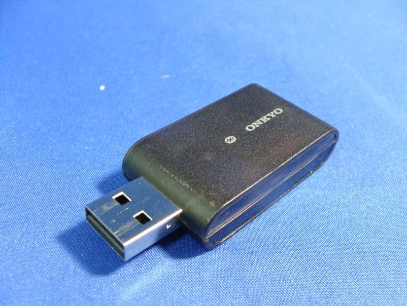
Click to zoom
Application Details
- Equipment Class
- DSS - Part 15 Spread Spectrum Transmitter
- Date of Grant
- Jun 03, 2012
- Application Purpose
- Original Equipment
- Date of Application
- May 24, 2012
- Equipment Note
- BLUETOOTH USB ADAPTER
- Frequency Range
- 2402.00000000 - 2480.00000000
- Company
- LITE-ON TECHNOLOGY CORP.
- Country
- Taiwan
Documents & Files
Document Text
Text extracted from the exhibit documents filed with the FCC. Open a document above to read the original.
Users Manual
4 1 5 2 6 3 (C) Copyr ight 2012 Onkyo Sound & Vision Corporation Japan. All rights reserved. D1204-1 * 2 9 4 0 1 2 1 8 A * SN 29401218A 2-1, Nisshin-cho, Neyagawa-shi, OSAKA 572-8540, JAPAN Tel: 072-831-8023 Fax: 072-831-8163 http://www.onkyo.com/ 18 Par k Way, Upper Saddle River , N.J. 07458, U.S .A. Tel: 800-229-1687, 201-785-2600 Fax: 201-785-2650 http://www.us.onkyo.com/ Liegnitzerstrasse 6, 82194 Groebenzell, GERMANY Tel: +49-8142-4401-0 Fax: +49-8142-4208-213 http://www.eu.onkyo.com/ The Coach House 81A High Street, Marlo w, Buckinghamshire, SL7 1AB, UK Tel: +44-(0)1628-473-350 Fax: +44-(0)1628-401-700 Unit 1033, 10/F, Star House, No 3, Salisbur y Road, Tsim Sha Tsui Kowloon, Hong Kong. Tel: 852-2429-3118 Fax: 852-2428-9039 http://www.onkyochina.com/ 1301, 555 Tower , No.555 West NanJin Road, Jin an, Shanghai, China 200041, Tel: 86-21-52131366 Fax: 86-21-52130396 http://www.cn.onkyo.com/ Instruction Manual Manuel d’instructions Manual de Instrucciones Manuale di istruzioni Bedienungsanleitung Gebruiksaanwijzing Bruksanvisning Փ⫼ݞ Փ⫼ݠ EnFrEsDeItNlSvCtCsRuJa Ar English Playing Back via Bluetooth Note yIf your mobile phone supports A2DP protocol, its music will play through the unit. yYou can build a Bluetooth connection with a mobile phone or any other Bluetooth-enabled devices. 1 Connect the unit to the compatible amplifier and set the input selector of the amplifier to USB. yCompatible with new-series (TX-NRx1x and higher) Onkyo AV receivers. For further details, visit the Onkyo web site. (www.onkyo.com) The adapter can only be used with the components listed in the URL. (It cannot be used with computers, for example.) 2 Press the PAIRING button on the unit to put the unit into the pairing mode. yThe indicator starts blinking. 3 During this period, you can operate the mobile phone or Bluetooth-enabled device to pair with the unit within a 10 m (33 ft) range. yThe unit may not work as normal depending on the circumstance even though the unit is placed within the 10 m (33 ft) range. In such cases, get the Bluetooth-enabled device closer to the unit and retry the operation. 4 Once the unit is detected and its name “Onkyo UBT-1” appears on the display of your Bluetooth- enabled device, select the “Onkyo UBT-1”. If a prompt requests a password, key in the “0000”. yWhen a Bluetooth connection is established successfully, the indicator will be solid on. 5 Play back the sound on your Bluetooth-enabled device. The sound from the connected device is output from the amplifier. yWhen disconnecting on your Bluetooth-enabled device, the indicator on the unit will go out. Note yIf there is no sound output even after the paring is done successfully, consult the user manual of the Bluetooth-enabled device, and then select the “Onkyo UBT-1” as the audio output device. Troubleshooting Bluetooth connection cannot be built. yWhen building a Bluetooth connection between the unit and your device for the first time, if the connection is fail, you need to power off your device and power on again to clear the device name, and build the connection again. yWhen connecting the unit to the USB terminal on the rear side of the amplifier, interference may occur and the connection distance may be shortened. To avoid this problem, connect the unit to the USB terminal on the front side of the amplifier. Specification Version: Bluetooth 3.0 Output: Class2 (10 m) USB Interface: USB 2.0 FULL Speed Profile: A2DP1.2 (A2DP codec supports SBC, AAC and aptX* decode.) Dimension (W × H × D): 56 mm × 24 mm × 11 mm (2-3/16” × 15/16” × 7/16”) Weight: 10 g (0.4 oz) Design and specifications are subject to change without notice. * aptX is a registered trademark of CSR plc. Français Lecture via Bluetooth Note ySi votre téléphone portable prend en charge le protocole A2DP, la musique pourra être jouée à travers cette unité. yVous pouvez établir une connexion Bluetooth avec un téléphone portable ou tout autre appareil équipé de Bluetooth. 1 Branchez l’appareil à un amplificateur compatible et réglez le sélecteur d’entrée de l’amplificateur sur USB. yCompatible avec les nouvelles séries (TX-NRx1x et modèles au-dessus) d’ampli-tuner AV Onkyo. Consultez le site Web d’Onkyo pour de plus amples détails. (www.onkyo.com) L’adaptateur peut uniquement être utilisé avec les composants figurant dans la section URL. (Il ne peut pas être utilisé avec les ordinateurs, par exemple.) 2 Appuyez sur le bouton PAIRING de l’appareil afin de le mettre en mode appariement. yLe témoin commence à clignoter. 3 Pendant ce temps là, vous pouvez utiliser votre téléphone portable ou tout autre appareil équipé de Bluetooth pour l’apparier à l’unité dans un rayon de 10 m (33 pieds). yL’appareil risque de ne pas fonctionner normalement bien que l ’unité soit placée dans un rayon de 10 m (33 pieds). Dans tels cas, rapprochez l’appareil équipé de Bluetooth à l’unité et essayez à nouveau. 4 Une fois l’appareil détecté et que le nom « Onkyo UBT-1 » s’affiche sur l’écran de votre appareil équipé de Bluetooth, sélectionnez l’option « Onkyo UBT-1 ». Si un mot de passe est demandé , saisissez « 0000 ». yQuand la connexion Bluetooth a été établie avec succès , le témoin reste allumé en continu. 5 Réécoutez le son sur votre appareil équipé de Bluetooth. Le son provenant de l’appareil connecté est émis par l’amplificateur. yLors de la déconnexion de votre appareil équipé de Bluetooth, le témoin de l’unité s’éteint. Note ySi aucun son n’est émis quand bien même l’appariement aurait été fait avec succès, consultez le manuel d’utilisation de votre appareil équipé de Bluetooth, puis sélectionnez l’option « Onkyo UBT-1 » comme périphérique de sortie audio. Résolution des problèmes La connexion Bluetooth ne peut être établie. yLorsque vous établissez pour la première fois une connexion Bluetooth entre l’unité et votre appareil, si la connexion échoue, vous devez éteindre puis rallumer votre appareil afin d’effacer le nom du périphérique et établir de nouveau la connexion. yLorsqu…
Text truncated - open the document above for the full version.
Attestation Statements
LITE-ON Technology Corp. FCC ID.: PPQ-UBT1 4F, No.90, Chien 1 Rd., Chung-Ho,Taipei Hsien,Taiwan 235Tel : 886-2-2222-6181 Federal Communications Commission May 14., 2012 Authorization and Evaluation Division ATTESTATION FCC ID: PPQ-UBT1 Product: BLUETOOTH USB ADAPTER Model: UBT-1 We don't provide any controls or software to allow operation outside the USA frequency band when we sell this product in USA. Sincerely, ---------------------------------------------------- TC Wu / Director LITE-ON Technology Corp.
Cover Letter(s)
LITE-ON Technology Corp. FCC ID.: PPQ-UBT1 4F, No.90, Chien 1 Rd., Chung-Ho,Taipei Hsien,Taiwan 235 Tel : 886-2-2222-6181 LITE-ON Technology Corp. 4F, No.90, Chien 1 Rd., Chung-Ho,Taipei Hsien,Taiwan 235 Tel : 886-2-2222-6181 Fax: 886-2-2226-6749 Federal Communications Commission May 14., 2012 Authorization and Evaluation Division Confidentiality Request Pursuant to Sections 0.457 and 0.459 of the Commission’s Rules, the Applicant Hereby requests confidential treatment of information accompanying this Application As outlined below: Schematics: (UBT-1) Schem Block Diagram: (UBT-1) BlkDia Operational Description: (UBT-1) OPDes The above materials contain trade secrets and proprietary information not customarily Released to the public. The public disclosure of these matters might be harmful to the Applicant and provide unjustified benefits to its competitors. The Applicant understands that pursuant to Rule 0.457, disclosure of this Application and all accompanying documentation will not be made before the date of the Grant for this application. Sincerely, ---------------------------------------------------- TC Wu / Director LITE-ON Technology Corp.
External Photos
Report No.: 125109R-RFUSP29V01 Page : 1 of 7 Attachment 2 : EUT Detailed Photographs (1) EUT Photo (2) EUT Photo Report No.: 125109R-RFUSP29V01 Page : 2 of 7 (3) EUT Photo (4) EUT Photo
ID Label/Location Info
LITE-ON Technology Corp. FCC ID.: PPQ-UBT1 4F, No.90, Chien 1 Rd., Chung-Ho,Taipei Hsien,Taiwan 235Tel : 886-2-2222-6181 FCC ID Label
ID Label/Location Info
LITE-ON Technology Corp. FCC ID.: PPQ-UBT1 4F, No.90, Chien 1 Rd., Chung-Ho,Taipei Hsien,Taiwan 235Tel : 886-2-2222-6181 The FCC ID and will be placed on the equipment as shown in the photograph below.
Internal Photos
Report No.: 125109R-RFUSP29V01 Page : 3 of 7 (5) EUT Photo (6) EUT Photo Report No.: 125109R-RFUSP29V01 Page : 4 of 7 (7) EUT Photo (8) EUT Photo Report No.: 125109R-RFUSP29V01 Page : 5 of 7 (9) EUT Photo (10) EUT Photo Report No.: 125109R-RFUSP29V01 Page : 6 of 7 (11) EUT Photo (12) EUT Photo Report No.: 125109R-RFUSP29V01 Page : 7 of 7 (13) EUT Photo (14) EUT Photo
RF Exposure Info
RF Exposure Statement 1. Standard Applicable According to 1.1307 (b)(1), systems operating under the provisions of this section shall be operated in a manner that ensure that the public is not exposed to radio frequency energy level in excess of the Commission’s guideline. 2. Measurement Result: This is a portable device and the max peak output power (EIRP) is 4.68dBm, which is equal to 2.94 mW, Lower that low threshold (60/f GHz) mW = 25 mW (f=2.4GHz), d <20 cm general population category. The SAR/MPE measurement is not necessary.
Test Report
Report No. 125109R-RFUSP29V01 Page: 1 of 75 Test Report Product Name BLUETOOTH USB ADAPTER Model No. UBT-1 FCC ID. PPQ-UBT1 Applicant LITE-ON TECHNOLOGY CORP. Address 4F, 90, Chien 1 Road, Chung Ho, Taipei Hsien 235, Taiwan, R.O.C. Date of Receipt May 03, 2012 Issued Date May 08, 2012 Report No. 125109R-RFUSP29V01 Report Version V1.0 The Test Results relate only to the samples tested. The test report shall not be reproduced except in full without the written approval of QuieTek Corporation. This report must not be used to claim product endorsement by NVLAP any agency of the U.S. Government Report No. 125109R-RFUSP29V01 Page: 2 of 75 Test Report Certification Issued Date: May 08, 2012 Report No.: 125109R-RFUSP29V01 Product Name BLUETOOTH USB ADAPTER Applicant LITE-ON TECHNOLOGY CORP. Address 4F, 90, Chien 1 Road, Chung Ho, Taipei Hsien 235, Taiwan, R.O.C. Manufacturer DONG GUAN G-COM COMPUTER CO., LTD. Model No. UBT-1 FCC ID. PPQ-UBT1 EUT Rated Voltage DC 5V EUT Test Voltage AC 120V/ 60Hz Trade Name ONKYO Applicable Standard FCC CFR Title 47 Part 15 Subpart C: 2010 ANSI C63.4: 2003 Test Result Complied The Test Results relate only to the samples tested. The test report shall not be reproduced except in full without the written approval of QuieTek Corporation. This report must not be used to claim product endorsement by NVLAP any agency of the U.S. Government Documented By : ( Senior Adm. Specialist / Rita Huang ) Tested By : ( Engineer / Nowal Kuo ) Approved By : (Manager / Vincent Lin ) Report No. 125109R-RFUSP29V01 Page: 3 of 75 TABLE OF CONTENTS Description Page 1. GENERAL INFORMATION ...............................................................................................................5 1.1. EUT Description......................................................................................................................................5 1.2. Operational Description...........................................................................................................................7 1.3. Tested System Details..............................................................................................................................8 1.4. Configuration of Tested System ..............................................................................................................8 1.5. EUT Exercise Software ...........................................................................................................................9 1.6. Test Facility ...........................................................................................................................................10 2. CONDUCTED EMISSION ................................................................................................................ 11 2.1. Test Equipment ......................................................................................................................................11 2.2. Test Setup ..............................................................................................................................................11 2.3. Limits.....................................................................................................................................................12 2.4. Test Procedure .......................................................................................................................................12 2.5. Uncertainty ............................................................................................................................................12 2.6. Test Result of Conducted Emission .......................................................................................................13 3. PEAK POWER OUTPUT ..................................................................................................................15 3.1. Test Equipment ......................................................................................................................................15 3.2. Test Setup ..............................................................................................................................................15 3.3. Limit .....................................................................................................................................................15 3.4. Test Procedure .......................................................................................................................................15 3.5. Uncertainty ............................................................................................................................................15 3.6. Test Result of Peak Power Output .........................................................................................................16 4. RADIATED EMISSION .....................................................................................................................18 4.1. Test Equipment ......................................................................................................................................18 4.2. Test Setup ..............................................................................................................................................18 4.3. Limits.....................................................................................................................................................19 4.4. Test Procedure .......................................................................................................................................20 4.5. Uncertainty ............................................................................................................................................20 4.6. Test Result of Radiated Emission ..........................................................................................................21 5. RF ANTENNA CONDUCTED TEST.....................................................................…
Text truncated - open the document above for the full version.
Test Report
Report No. 125109R-RFUSP29V01 Page: 53 of 75 7. Channel Number 7.1. Test Equipment Equipment Manufacturer Model No./Serial No. Last Cal. Spectrum Analyzer R&S FSP40 / 100170 Jun, 2011 Spectrum Analyzer Agilent E4407B / US39440758 Jun, 2011 X Spectrum Analyzer Agilent N9010A / MY48030495 Apr., 2012 Note: 1. All equipments are calibrated every one year. 2. The test instruments marked by “X” are used to measure the final test results. 7.2. Test Setup 7.3. Limit Frequency hopping systems operating in the 2400-2483.5 MHz bands shall use at least 75 hopping frequencies. 7.4. Test Procedure The EUT was setup to ANSI C63.4, 2003; tested to FHSS test procedure of FCC Public Notice DA 00-705 for compliance to FCC 47CFR 15.247 requirements. 7.5. Uncertainty N/A SMA Connecter EUT Spectrum Analyzer RF Cable Report No. 125109R-RFUSP29V01 Page: 54 of 75 7.6. Test Result of Channel Number Product : BLUETOOTH USB ADAPTER Test Item : Channel Number Test Site : No.3 OATS Test Mode : Mode 1: Transmit - 1Mbps (GFSK) Frequency Range (MHz) Measurement (Hopping Channel) Required Limit (Hopping Channel) Result 2402 ~ 2480 79 >75 Pass 2402-2421MHz 2422-2441MHz 2442-2461MHz 2462-2480MHz Report No. 125109R-RFUSP29V01 Page: 55 of 75 Product : BLUETOOTH USB ADAPTER Test Item : Channel Number Test Site : No.3 OATS Test Mode : Mode 2: Transmit - 3Mbps (8DPSK) Frequency Range (MHz) Measurement (Hopping Channel) Required Limit (Hopping Channel) Result 2402 ~ 2480 79 >75 Pass 2402-2421MHz 2422-2441MHz 2442-2461MHz 2462-2480MHz Report No. 125109R-RFUSP29V01 Page: 56 of 75 8. Channel Separation 8.1. Test Equipment Equipment Manufacturer Model No./Serial No. Last Cal. Spectrum Analyzer R&S FSP40 / 100170 Jun, 2011 Spectrum Analyzer Agilent E4407B / US39440758 Jun, 2011 X Spectrum Analyzer Agilent N9010A / MY48030495 Apr., 2012 Note: 1. All equipments are calibrated every one year. 2. The test instruments mark by “X” are used to measure the final test results. 8.2. Test Setup 8.3. Limit Frequency hopping systems shall have hopping channel carrier frequencies separated by a minimum of 25 kHz or the 20 dB bandwidth of the hopping channel, whichever is greater. 8.4. Test Procedure The EUT was setup to ANSI C63.4, 2003; tested to FHSS test procedure of FCC Public Notice DA 00-705 for compliance to FCC 47CFR 15.247 requirements. 8.5. Uncertainty ± 150Hz SMA Connecter EUT Spectrum Analyzer RF Cable Report No. 125109R-RFUSP29V01 Page: 57 of 75 8.6. Test Result of Channel Separation Limit Limit of (2/3)*20dB Channel No. Frequency (MHz) Measurement Level (kHz) (kHz) Bandwidth (kHz) Result 00 2402 1000 >25 kHz 740.0 Pass 39 2441 1000 >25 kHz 740.0 Pass 78 2480 1000 >25 kHz 746.7 Pass NOTE: The 20dB Bandwidth is refer to section 10. Channel 00 2402MHz Product : BLUETOOTH USB ADAPTER Test Item : Channel Separation Test Site : No.3 OATS Test Mode : Mode 1: Transmit - 1Mbps (GFSK) Report No. 125109R-RFUSP29V01 Page: 58 of 75 Channel 39 2441MHz Channel 78 2480 MHz Report No. 125109R-RFUSP29V01 Page: 59 of 75 Limit Limit of (2/3)*20dB Channel No. Frequency (MHz) Measurement Level (kHz) (kHz) Bandwidth (kHz) Result 00 2402 1000 >25 kHz 940.0 Pass 39 2441 1000 >25 kHz 926.7 Pass 78 2480 1000 >25 kHz 920.0 Pass NOTE: The 20dB Bandwidth is refer to section 10. Channel 00 2402MHz Product : BLUETOOTH USB ADAPTER Test Item : Channel Separation Test Site : No.3 OATS Test Mode : Mode 2: Transmit - 3Mbps (8DPSK) Report No. 125109R-RFUSP29V01 Page: 60 of 75 Channel 39 2441MHz Channel 78 2480 MHz Report No. 125109R-RFUSP29V01 Page: 61 of 75 9. Dwell Time 9.1. Test Equipment Equipment Manufacturer Model No./Serial No. Last Cal. Spectrum Analyzer R&S FSP40 / 100170 Jun, 2011 Spectrum Analyzer Agilent E4407B / US39440758 Jun, 2011 X Spectrum Analyzer Agilent N9010A / MY48030495 Apr., 2012 Note: 1. All equipments are calibrated every one year. 2. The test instruments marked by “X” are used to measure the final test results. 9.2. Test Setup 9.3. Limit The dwell time shall be the average time of occupancy on any frequency shall not be greater than 0.4 seconds within a 30 second period. 9.4. Test Procedure The EUT was setup to ANSI C63.4, 2003; tested to FHSS test procedure of FCC Public Notice DA 00-705 for compliance to FCC 47CFR 15.247 requirements. 9.5. Uncertainty ± 25msec SMA Connecter EUT Spectrum Analyzer RF Cable Report No. 125109R-RFUSP29V01 Page: 62 of 75 9.6. Test Result of Dwell Time Product : BLUETOOTH USB ADAPTER Test Item : Dwell Time Test Site : No.3 OATS Test Mode : Mode 1: Transmit - 1Mbps (GFSK) (Channel 00,39,78 –DH5) Frequency (MHz) Time slot length (ms) Hopping of Number Sweep time (ms) Duty cycle Dwell Time (Sec) Limit (Sec) Result 2402 2.900 13 50 0.75 0.302 0.4 Pass 2441 2.910 13 50 0.76 0.303 0.4 Pass 2480 2.900 13 50 0.75 0.302 0.4 Pass Duty cycle =((Time slot length(ms)*Hopping of Number) / Sweep time (ms) Dwell time = (Duty cycle /79) * (79*0.4) CH 00 Time Interval between hops CH 00 Transmission Time CH39 Time Interval between hops CH 39Transmission Time Report No. 125109R-RFUSP29V01 Page: 63 of 75 CH 78 Time Interval between hops CH 78 Transmission Time Note: The dwell times of the packet type of DH1, DH3, and DH5 are tested. Only the worst case is shown on the report. Report No. 125109R-RFUSP29V01 Page: 64 of 75 Product : BLUETOOTH USB ADAPTER Test Item : Dwell Time Test Site : No.3 OATS Test Mode : Mode 2: Transmit - 3Mbps (8DPSK) (Channel 00,39,78 –DH5) Frequency (MHz) Time slot length (ms) Hopping of Number Sweep time (ms) Duty cycle Dwell Time (Sec) Limit (Sec) Result 2402 2.920 13 50 0.76 0.304 0.4 Pass 2441 2.900 13 50 0.75 0.302 0.4 Pass 2480 2.900 13 50 0.75 0.302 0.4 Pass Duty cycle =((Time slot length(ms)*Hopping of Number) / Sweep time (ms) Dwell time = (Duty cycle /79) * (79*0.4) CH 00 Time Interval between hops CH 00 Transmission Time CH39 Time Interval between hops CH 39Transmission Time Report No. 125109R-RFUSP29V01 Page: 65 of 75 CH 78 Time Interval between hops CH 78 Transmission Time Note: The dwell times of t…
Text truncated - open the document above for the full version.
Test Setup Photos
Report No.: 125109R-RFUSP29V01 Page : 1 of 3 Attachment 1: EUT Test Setup Photographs Front View of Conducted Test Back View of Conducted Test Report No.: 125109R-RFUSP29V01 Page : 2 of 3 Front View of Radiated Test Back View of Radiated Test Report No.: 125109R-RFUSP29V01 Page : 3 of 3 Front View of Radiated Test (Horn) Back View of Radiated Test (Horn)
Contact Information
Applicant
TC Wu(Deputy Director(R & D Division))
Technical Contact
QuieTek CorporationSabina Chen
[email protected]886-2-8601-3788
No. 5-22, Rueishu Keng, Linkou Dist., · Taiwan
Test Firm
DEKRA Testing and Certification Co., Ltd.Sky Hsu
Technical Specifications
| # | Rule Parts | Frequency Range | Power Output |
|---|---|---|---|
| 1 | 15C | 2.40 GHz - 2.48 GHz | 1.85 mW |
Other Applications from LITE-ON TECHNOLOGY CORP.
PPQ-WPB8326
Sep 05, 2025Indoor Wi-Fi 7 2x2 Tri-Band Enterprise Access Point
Equipment Class
6ID - 15E 6 GHz Low Power Indoor Access Point
PPQ-WCBN3605L
Aug 30, 2023802.11b/g/n 1Tx1R + BT5.0 IOT Combo Module
Equipment Class
DTS - Digital Transmission System
PPQ-WCBN3610L
Jul 24, 2023802.11 b/g/n, 1T1R 2.4G Wireless IoT Module
Equipment Class
DTS - Digital Transmission System
PPQ-WPX8324
Jan 30, 2023Access Point
Equipment Class
DTS - Digital Transmission System
PPQ-WM6321
Dec 16, 2021WM6321
Equipment Class
NII - Unlicensed National Information Infrastructure TX