PPQ-VN910FGPS Navigation System and Music Player
LITE-ON TECHNOLOGY CORP.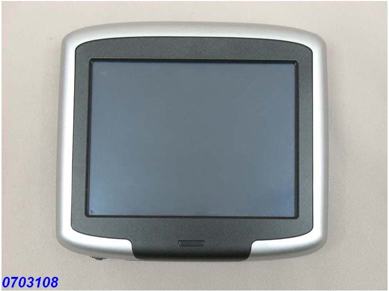
Click to zoom
Application Details
- Equipment Class
- DXX - Part 15 Low Power Communication Device Transmitter
- Date of Grant
- May 29, 2007
- Application Purpose
- Original Equipment
- Date of Application
- May 28, 2007
- Equipment Note
- GPS Navigation System and Music Player
- Frequency Range
- 88.10000000 - 107.90000000
- Company
- LITE-ON TECHNOLOGY CORP.
- Country
- Taiwan
Documents & Files
Document Text
Text extracted from the exhibit documents filed with the FCC. Open a document above to read the original.
Users Manual
VN910 User Guide VN910 User Guide: February2007 All reasonable attempts are made to ensure that this User Guide is up-to-date and accurate. However, please note that due to circumstances beyond our control, certain appearances, features or operations may vary slightly from those described here. Contents are subject to change without notice. Contents Important Safety Instructions General.......................................................................................6 Working Conditions ....................................................................6 Design Limitations ......................................................................7 User Scenario/Habit ...................................................................7 Introduction About the VN910 ........................................................................8 Package Contents ................................................................8 Features................................................................................9 Front ................................................................................9 Rear ................................................................................9 Top ................................................................................10 Bottom ...........................................................................10 Left and ri ght sides........................................................10 Initial Setup Switch the Device On ...............................................................11 Screen Calibration ....................................................................11 Set the Time/Date.....................................................................11 Insert the SD/MMC Card ..........................................................12 Connecting to a Computer Establishingdevice-PC connection ....................................13 Charging the Device Battery Indicators......................................................................14 LED indicators ....................................................................14 UsingtheAC Adaptor...............................................................14 Ca r Installation Setting up the VN910 in your vehicle ....................................... 15 Usin g the suction cup ...................................................15 Basics Navigation Options................................................................... 19 Using the touch screen....................................................... 19 Using the hard keys............................................................ 19 Main menu screen................................................................... 19 Navigation Accessingthe Navigation Function.......................................... 21 MP3 Player Accessing the MP3 Player ....................................................... 22 Mp3 Player Screen Definitions................................................. 23 Display................................................................................ 23 Buttons ............................................................................... 23 Using the Player....................................................................... 24 Playing music ..................................................................... 24 Adjusting the volume .......................................................... 24 Changing the order of tracks .............................................. 24 Repeating tracks ................................................................ 24 Creatingaplaylist............................................................... 25 Photo Viewer Accessing the Photo Viewer .................................................... 26 Using the Photo Viewer ........................................................... 27 Viewing photos...................................................................27 Usingthe slideshow............................................................28 Settings Accessing the Setup Screen ....................................................29 Adjusting the Settings...............................................................30 Setting the Time/Date .........................................................30 Changing the Time Zone...............................................30 Changing the Time/Date ...............................................32 Volume................................................................................33 FM Transmitter ...................................................................34 Screen options ....................................................................36 Adjusting the Brightness ...............................................36 Adjusting the Idle Time..................................................36 Calibrating the Screen...................................................37 Choosing the Language......................................................38 System Information .............................................................39 Resetting the Device Performing a soft reset .............................................................40 Performingahard reset............................................................40 TroubleshootingGuide Important Safety Instructions Please read and follow these safety instructions before using your device for the first time, and save them forfuture reference. General • Keep away from extremely hot, cold or humid conditions. • Do not allow the device to get wet. • Avoid shocks or vibrations. • Do not open your device. Any attempts to open this device will void the warranty. • Wipe the touch screen only with a lint-free cloth, slightly dampened, while the device is switched off. • Do not place objects on topof the device. Working Conditions • Do not charge the device in extremely hot or cold conditions. • If the red LED is flashing, please recharge the device immediately. • Please use the car charger when …
Text truncated - open the document above for the full version.
Cover Letter(s)
1. Describe the operation of the device. The EUT was supplied with DC 12V from adapter and battery And the FM Transmitter can be used to transmit audio as a radio signal that can be picked up on you card radio 2. Provide information on the device and its antenna. This device is a FM transmitter operation at 88.1MHz to 107.9MHz. The EUT uses a permanently connected antenna. -Antenna: N/A -Antenna Type: Printed -Connector Type: N/A 3. How is it installed? Insert SD card into the connector on the top of the EUT. Play MP3 continuously by adapter, then place the whole set onto of the testing site for test. 4. Describe the test procedure used. (OAT’s, In situ, etc.) The device was only tested on a OAT’s as the antenna is integral to the device (internal). Radiated emissions were invested cover the frequency range from 30MHz to 1000MHz using a receiver RBW of 120KHz record QP reading, and the frequency over 1GHz using a spectrum analyzer RBW of 1MHz and 10Hz VBW record Average reading. (15.209 paragraph), the Peak reading (1MHz RBW/VBW) recorded also on the report. The EUT for testing is arranged on a wooden turntable. If some peripherals apply to the EUT, the peripherals will be connected to EUT and the whole system. During the test, all cables were arranged to produce worst-case emissions. The signal is maximized through rotation. The height of antenna and polarization is changing constantly for exploring for maximum signal level. The height of antenna can be up to 4 meters and down to 1 meter. The measurement for radiated emission will be done at the distance of three meters unless the signal level is too low to measure at that distance. In the case of the reading under noise floor, a pre-amplifier is used and/or the test is conducted at a closer distance. And then all readings are extrapolated back to the equivalent three meter reading using inverse scaling with distance. bandwidth requirement a. The transmitter output (antenna port) was connected to the spectrum analyzer in peak hold mode. b. The resolution bandwidth of 10 kHz and the video bandwidth of 10 KHz were used. c. Measured the spectrum width with power higher than 20dB below carrier. 5. If tested in a care, describe how was it configured and tested. N/A 6. At the present time, FM transmitters (subject to 15.239) tested in vehicles must also be tested on a table. Provide both sets of data. All data must be compliant. The EUT was only performed on the test table. All the test data was complied with FCC 15. 239 requirement. Please refer to Page 34 and Page 35 of the User’s Manual. 7. Was the tuning range properly verified? The test lab should indicate in the report that the tuning controls were manually adjusted to verify maximum tuning range. Yes. During the bandwidth test, the EUT was tested with the maximum audio input (800mVp-p). 8. Use a typical audio file from a typical device. E.g. do not use a 1KHz signal from a signal generator. Audio input was generated from an SD card to the device and tested under normal operating conditions. 9. Provide the test report showing compliance with the rules.
Cover Letter(s)
April 4, 2007 Federal Communications Commission Authorization and Evaluation Division FCC ID:PPQ-VN910F Confidentiality Request Pursuant to Sections 0.457 and 0.459 of the Commission’s Rules, the Applicant Hereby requests confidential treatment of information accompaniment this Application As outlined below: 1. Block Diagram, 2. Schematic Diagram, The above materials contain trade secrets and proprietary information not customarily released to the public. The public disclosure of these matters might be harmful to the Applicant and provide unjustified benefits to its competitors. The Applicant understands that pursuant to Rule 0.457, disclosure of this Application and all accompanying documentation will not be made before the date of the Grant for this application Sincerely, Peter SH Wang / EMC Senior Engineer Applicant: LITE-ON TECHNOLOGY CORP. Address: 4F, 3, Lane 768, Sec. 4, Pateh Road, Taipei 115, Taiwan, R. O. C. TEL: +886-2-2788-4766 FAX: +886-2-2789-2476
Cover Letter(s)
American Telecommunications Certification Body Inc. 6731 Whittier Ave, McLean, VA 22101 April 14, 2007 RE: LITE-ON Technology Corp. FCC ID: PPQ-VN910F I have a few comments on this Application. Depending on your responses, kindly understand there may be additional comments. 1.) The name, address and contact person listed on the FCC database for LITE-ON under the Grantee code PPQ does not match the application form, the confidentiality request, or the PIA. All this information must be updated before this Grant can proceed. Under who’s authority does Peter Wang speak on behalf of LITE-ON? 2.) Please provide a block diagram of the RF section of this device. I do not find any block diagram specific to the 88-108MHz transmitter. 3.) Please provide better, clearer internal photographs. May I suggest that either the photos or the paper be rotated 90 degrees so as to provide a larger and better fit for the photos? 4.) This device has an FCC logo indicating that the Rules for DofC should apply. You are reminded that testing as a Part 15B computer peripheral is required since this device can access a USB port. Kindly indicate where the DofC testing has taken place. 5.) FYI: This device is very low power. Therefore the RF exposure and co-location prohibitions seen in the Manual are not required. 6.) Please review again the “Permit But Ask” document sent yesterday. Page two begins a list of ten items which must specifically be addressed by any applicant for Certification under 15.239. Please observe that there are ten items. We urge all applicants to provide a separate document (similar to the Modular Approval request letter) specifying how all these different requirements are met. As an example, I do not find any specific reference to how this device has been modulated during testing and using what source. If an analog input the transmitter is provided, this must also be tested. 7.) Your Test Setup photos omit the use of a computer. All radiated testing shall be performed with all input ports filled. For this case, it would be very appropriate that a PC be used in all radiated and conducted testing under Part 15B and 15C. 8.) It is not appropriate to measure band edge compliance of a 200KHz wide signal using a 100KHz wide RBW. Please retake your band edge emissions data using a 10KHz RBW in both mono and stereo modes, and make sure a “worst case” audio source is used. William H. Graff President and Director of Engineering mailto: [email protected] The items indicated above must be submitted before processing can continue on the above referenced application. Failure to provide the requested information may result in application termination. Correspondence should be considered part of the permanent submission and may be viewed from the Internet after a Grant of Equipment Authorization is issued. Please do not respond to this correspondence using the email reply button. In order for your response to be processed expeditiously, you must submit your documents through the AmericanTCB.com website. Also, please note that partial responses increase processing time and should not be submitted. Any questions about the content of this correspondence should be directed to the sender.
Cover Letter(s)
FCC Home | Search | Updates | E-Filing | Initiatives | For Consumers | Find People Office of Engineering and Technology FCC > FCC E-filing > Inquiry System Home Page > Inquiry Confirmation FCC Site Map OET Home Page Site Options Knowledge DataBase Search Detail Criteria Search Submit An Inquiry Reply to an Inquiry Response Category List FAQ Search View Instructions Related Sites Equipment Authorization System (EAS) Telecommunications Certification Bodies (TCB) Your inquiry has been submitted to the Laboratory Division of the FCC Office of Engineering and Technology. You will receive a response as soon as possible. Please be sure to retain the inquiry tracking number displayed for future reference and questions concerning the status of this inquiry. Inquiry Tracking Number: 370636 Date of Submission: 05/24/2007 Subject: 15.239 GPS Navigation System Question: Gentlemen, AmericanTCB seeks guidance for a low power 88-108 MHz personal FM broadcast band transmitter used as a voice link between a GPS receiver an an automotive FM broadcast receiver. All documentation specified within the Permit But Ask procedure is provided. Your earliest consideration would be appreciated. Best Regards, Bill Please send any comments or suggestions for this site to OET Systems Support Federal Communications Commission 445 12th Street, SW Washington, DC 20554 More FCC Contact Information... Phone: 888-CALL-FCC (225-5322) TTY: 888-TELL-FCC (835-5322) Fax: 202-418-0232 E-mail: [email protected] - Privacy Policy - Web Policies & Notices - Customer Service Standards - Freedom of Information Act
External Photos
External Photos
ID Label/Location Info
VN910_LITEON device label VN910_LITEON Miranda Yang Miranda Yang 20070329 15mm Model No: VN910 DC input:DC 5V 1A FCC ID: PPQ-VN910F Made in China R2.5 R2.5 R2.5 E309222 3HRW I.T.E. XXXX
Internal Photos
Internal Photos
Operational Description
VN910 Operational Principle. 1. CPU, U1, Atlas 2 324MHz/FBGA have a 32-bit RISC processor integrated, operation frequency is 324MHz. It needs an external 12MHz (Y1) and 32.768KHz (Y2) crystal for reference frequency. 2. SDRAM, U2/U3, Samsung 32MB K4M561633G-BN75, 3.3V/138MHz 32-bit data bus. 3. Flash, 3.1 NAND1, HYNIX 1GB HY27UG08G5M-TP, (\\Options1:Samsung , Flash Memory ,K9F5608U0C-PCB0,256Mb*8, \\Options 2 :HYNIX,Flash Memory,HY27UF082G2A-TP,2Gb*8, \\Options 3 :HYNIX,Flash Memory,HY27UF084G2A-TP,4Gb*8,) 3.2 3.3V/138MHz 8-bit data bus. The NAND Flash can be used as a boot-loader during boot-up, or be used as a simple storage device (for both program and data). When the NAND Flash is sued as a boot-loader, the boot code will be stored in the first physical block of the NAND Flash and the rest of NAND Flash also can be used as simple storage device. 4. GPS, G_U1 GPS Receiver IC (SiGe SE4110L) It needs an external 16.367667MHz(G_Y1)crystal for reference frequency. GPS protocol standard -NMEA 0183 V2.0 12 CH 15x15mm Patch antenna receiver for GPS L1 (C/A-code) Acquisition sensitivity: -141dBm Tracking sensitivity: -153dBm The SE4110L includes an on-chip LNA and a low IF receiver with a linear AGC and 2-bit analogue-to-digital converter (ADC). The receiver incorporates a fully integrated image reject mixer so no SAW filter is required in many applications. There is also an on-chip IF filter. 4.1 PATCH ANTENNA (Cirocomm DA15) a.Frequency Range 1575.42 ± 1.023 MHz. b.GAIN 90° : -0.5 dBi Min. c.Polaration RHCP d.Axial ration 90° : Max 4.0dB 4.2 LNA a.Frequency Range 1575.42 ± 1.023 MHz b.Gain 14.5dB Min. 15 dB Typ.( + 25 °C± 5°C) c.Noise Figure 1.5 dB Max. ( + 25 °C± 5°C), 2.2 dB Max. ( + 85 °C) d.Output Impedance 50. e.Output VSWR 2.0 Max 5. FM, F_U1, FM transmitter IC NS 740A. Transmission Frequency: 88 MHz ~108 MHz External clock: 32.768 kHz (F_Y1) Integrated antenna. Antenna impedance: 50 ohm Transmission power output: -10 dBm ~ -7 dBm
Test Report
Report No.: NEI-FCCP-1-0703108 Page 1 of 48 Neutron Engineering Inc. Radio TEST Report FCC ID: PPQ-VN910F This report concerns (check one) : Original Grant Class II Change Issued Date : Apr. 09, 2007 Project No. : 0703108 Equipment : GPS Navigation Model Name : VN910 Applicant: LITE-ON Technology Corp Address: 6F, No. 9, Lane 768, Sec. 4, Pateh Rd. Ta i p e i Ta i w a n , R . O . C . Tested by: Neutron Engineering Inc. EMC Laboratory Data of Test: Mar. 26, 2007 ~ May. 21, 2007 Testing Engineer : (Rush Kao) Technical Manager : (Jeff Yang) Authorized Signatory : (Andy Chiu) NEUTRON ENGINEERING INC. No. 132-1, Lane 329, Sec. 2, Palain Rd., Shijr City, Taipei, Taiwan TEL : (02) 2646-5426 FAX : (02) 2646-6815 Report No.: NEI-FCCP-1-0703108 Page 2 of 48 Neutron Engineering Inc. Declaration Neutron represents to the client that testing is done in accordance with standard procedures as applicable and that test instruments used has been calibrated with the standards traceable to National Measurement Laboratory (NML) of R.O.C., or National Institute of Standards and Technology (NIST) of U.S.A. Neutron's reports apply only to the specific samples tested under conditions. It is manufacture’s responsibility to ensure that additional production units of this model are manufactured with the identical electrical and mechanical components. Neutronshall have no liability for any declarations, inferences o r generalizations drawn by the client or others from Neutron issued reports. Neutron’s reports must not be used by the client to claim product endorsement by the authorities or any agency of the Government. This report is the confidential property of the client. As a mutual protection to the clients, the public and Neutron-self, extracts from the test report shall not be reproduced except in full with Neutron’s authorized written approval. Neutron’s laboratory quality assurance procedures are in compliance with the ISO Guide 17025 requirements, and accredited by the conformity assessment authorities listed in this test report. Limitation For the use of the authority's logo is limited unless the Test Standard(s)/Scope(s)/Item(s) mentioned in this test report is (are) included in the conformity assessment authorities acceptance respective. Report No.: NEI-FCCP-1-0703108 Page 3 of 48 Neutron Engineering Inc. Table of Contents Page 1 . CERTIFICATION 5 2 . SUMMARY OF TEST RESULTS 6 2.1 TEST FACILITY 7 2.2 MEASUREMENT UNCERTAINTY 7 3 . GENERAL INFORMATION 8 3.1 GENERAL DESCRIPTION OF EUT 8 3.2 DESCRIPTION OF TEST MODES 10 3.3 BLOCK DIGRAM SHOWING THE CONFIGURATION OF SYSTEM TESTED 11 3.4 DESCRIPTION OF SUPPORT UNITS 12 4 . EMC EMISSION TEST 13 4.1 CONDUCTED EMISSION MEASUREMENT 13 4.1.1 POWER LINE CONDUCTED EMISSION LIMITS 13 4.1.2 MEASUREMENT INSTRUMENTS LIST AND SETTING 13 4.1.3 TEST PROCEDURE 14 4.1.4 DEVIATION FROM TEST STANDARD 14 4.1.5 TEST SETUP 14 4.1.6 EUT OPERATING CONDITIONS 14 4.1.7 TEST RESULTS 15 4.2 RADIATED EMISSION MEASUREMENT 17 4.2.1 RADIATED EMISSION LIMITS 17 4.2.2 MEASUREMENT INSTRUMENTS LIST 18 4.2.3 TEST PROCEDURE 18 4.2.4 DEVIATION FROM TEST STANDARD 18 4.2.5 TEST SETUP 19 4.2.6 EUT OPERATING CONDITIONS 20 4.2.7 TEST RESULTS 21 4.3 BAND EDGE EMISSIONS MEASUREMENT 33 4.3.1 LIMITS OF BAND EDGE EMISSIONS MEASUREMENT 33 4.3.2 MEASURING INSTRUMENTS AND SETTING 33 4.3.3 TEST PROCEDURE 33 4.3.4 TEST SETUP LAYOUT 33 4.3.5 TEST DEVIATION 33 4.2.6 TEST RESULTS 34 5 . BANDWIDTH REQUIREMENT 42 5.1.1 LIMITS OF EMISSION BAND MEASUREMENT 42 5.1.2 MEASUREMENT INSTRUMENTS LIST 42 5.1.3 TEST PROCEDURE 42 Report No.: NEI-FCCP-1-0703108 Page 4 of 48 Neutron Engineering Inc. Table of Contents Page 5.1.4 TEST SETUP LAYOUT 42 5.1.5 TEST DEVIATION 42 5.1.6 EUT OPERATION DURING TEST 42 5.1.7 TEST RESULT OF 20dB SPECTRUM BANDWIDTH 43 6 . EUT TEST PHOTO 47 Report No.: NEI-FCCP-1-0703108 Page 5 of 48 Neutron Engineering Inc. 1. CERTIFICATION Equipment : GPS Navigation Tr a d e N a m e : Liteon Model Name : VN910 A p p l i c a n t : LITEON-ON Technology Corp Data of Test : Mar. 26, 2007 ~ May. 21, 2007 T e s t I t e m : ENGINEERING SAMPLE Standards : FCC Part15, Subpart C (15.239)/ ANCI C63.4 : 2003 The above equipment has been tested and found compliance with the requirement of the relative standards by Neutron Engineering Inc. EMC Laboratory. The test data, data evaluation, and equipment configuration contained in our test report (Ref No. NEI-FCCP-1-0703108) were obtained utilizing the test procedures, test instruments, test sites that has been accredited by the Authority of NVLAP and CNLA according to the ISO-17025 quality assessment standard and technical standard(s). Report No.: NEI-FCCP-1-0703108 Page 6 of 48 Neutron Engineering Inc. 2. SUMMARY OF TEST RESULTS Test procedures according to the technical standards: (Antenna to EUT distance is 3 m) FCC Part15, Subpart C Standard Test Item Limit Frequency Range (MHz) Judgment 15.207 Conducted Emission Class B 0.15 - 30 PASS 15.209 Radiated Emission Class B 30-1000 PASS 15.239 Radiated Emission 250 μV/m (48dBμV/m) @ 3m 88~108 PASS NOTE: (1)” N/A” denotes test is not applicable in this Test Report Report No.: NEI-FCCP-1-0703108 Page 7 of 48 Neutron Engineering Inc. 2.1 TEST FACILITY The test facilities used to collect the test data in this report is CO01/OS02 at the location of No.132-1, Lane 329, Sec. 2, Palain Road, Shijr City, Taipei, Taiwan. 2.2 MEASUREMENT UNCERTAINTY The reported uncertainty of measurement y ± U,where expended uncertainty U is based on a standard uncertainty multiplied by a coverage factor of k=2,providing a level of confidence of approximately 95 %。 A. Conducted Measurement : Test Site Method Measurement Frequency Range U,(dB) NOTE C01 ANSI150 KHz ~ 30MHz 1.94 B. Radiated Measurement : Test Site Method Measurement Frequency Range Ant. H / V U,(dB) NOTE OS-01 ANSI30MHz ~ 200MHz V 3.82 30MHz ~ 200MHz H 3.60 200MHz ~ 1,000MHz V 3.86 200MHz ~ 1,000MHz H 3.94 OS-02 ANSI30MHz ~ 200MHz V 2.48 30MHz ~ 200MHz H 2.16 200MHz ~ 1,000MHz V 2.50 200MHz ~…
Text truncated - open the document above for the full version.
Test Setup Photos
Test Setup Photos
Contact Information
Applicant
Sandra Liu(Associate Manager)
Technical Contact
Neutron EngineeringAnnie Yuan
[email protected]+886 2 2657 3299
B1, No. 37, Lane 365, YangGuang St · Taipei · Taiwan
Test Firm
BTL Inc.Andy Yeh
Technical Specifications
| # | Rule Parts | Frequency Range | Power Output |
|---|---|---|---|
| 1 | 15C | 88.1 MHz - 107.9 MHz | - |
Other Applications from LITE-ON TECHNOLOGY CORP.
PPQ-WPB8326
Sep 05, 2025Indoor Wi-Fi 7 2x2 Tri-Band Enterprise Access Point
Equipment Class
6ID - 15E 6 GHz Low Power Indoor Access Point
PPQ-WCBN3605L
Aug 30, 2023802.11b/g/n 1Tx1R + BT5.0 IOT Combo Module
Equipment Class
DTS - Digital Transmission System
PPQ-WCBN3610L
Jul 24, 2023802.11 b/g/n, 1T1R 2.4G Wireless IoT Module
Equipment Class
DTS - Digital Transmission System
PPQ-WPX8324
Jan 30, 2023Access Point
Equipment Class
DTS - Digital Transmission System
PPQ-WM6321
Dec 16, 2021WM6321
Equipment Class
NII - Unlicensed National Information Infrastructure TX