PPQ-WN2401A802.11a/b/g mini-PCI WLAN card
LITE-ON TECHNOLOGY CORP.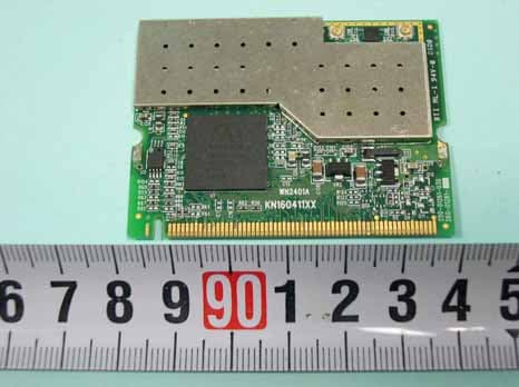
Click to zoom
Application Details
- Equipment Class
- DTS - Digital Transmission System
- Date of Grant
- Jun 20, 2005
- Application Purpose
- Original Equipment
- Date of Application
- Jun 20, 2005
- Equipment Note
- 802.11a/b/g mini-PCI WLAN card
- Frequency Range
- 2412.00000000 - 2462.00000000
- Company
- LITE-ON TECHNOLOGY CORP.
- Country
- Taiwan
Documents & Files
Document Text
Text extracted from the exhibit documents filed with the FCC. Open a document above to read the original.
Users Manual
Wireless LAN 802.11a/b/g Device 1 Introduction Your Stargate TV module func tions as a Wireless Local Area Network (WLAN) connecting with other wireless product(s) via 802.11 technology. 802.11 technology allows over-the-air connection between devices. Your Stargate TV module is equipped with an 802.11a/b/g product which allows fast (up to 54Mbps) connection rates . Installing the Wireless LAN 802.11a/b/g Device Antenna The Wireless LAN 802.11a/b/g Device is embedded in the Stargate TV module and need s the antenna supplied with your Stargate TV module to be connected. Once connected, your Stargate TV module is ready to begin functioning in station mode (as a client) with your Wireless Local Area Network. Note: It is assumed that there is an existing wireless LAN network with an Internet connection (please consult your ISP for further information). Package contents consist of an antenna with a connector located at the end (A) that screws into the antenna jack located on the back of the Stargate TV module (B). A) Antenna Installation 1. Screw the antenna connector (A) to the antenna jack (B) located on the back of the Stargate TV module. 2. Place the Stargate TV module on a table or place the antenna in an elevated and open area to achieve the best wireless performance . B) Troubleshooting Prior to contacting customer support check the following items and reboot the Stargate TV module: 1. Verify that both the Starga te TV module as well as the wireless broadband router/access point are powered. 2. Verify that the antenna is connected securely to the back of your Stargate TV module. English Wireless LAN 802.11a/b/g Device 2 C) Customer Support Customer support information can be obtained from System Warranty and Support Guide. INFORMATION TO USER Federal Communication Commission Interference Statement This equipment has been tested and found to comply with the limits for a Class B digital device, pursuant to Part 15 of the FCC Rules. These limits are designed to provide reasonable protection against harmful interference in a residential installation. This equipment generates, uses and can radiate radio frequency energy and, if not installed and used in accordance with the instructions, may cause harmful interference to radio communications. However, there is no guarantee that interference will not occur in a particular installation. If this equipment does cause harmful interference to radio or television reception, which can be determined by turning the equipment off and on, the user is encouraged to try to correct the interference by one of the following measures: -Reorient or relocate the receiving antenna. Wireless LAN 802.11a/b/g Device 3 -Increase the separation between the equipment and receiver. -Connect the equipment into an outlet on a circuit different from that to which the receiver is connected. -Consult the dealer or an experienced radio/TV technician for help. This device complies with Part 15 of the FCC Rules. Operation is subject to the following two conditions: (1) This device may not cause harmful interference, and (2) this device must accept any interference received, including interference that may cause undesired operation. FCC Caution: Any changes or modifications not expressly approved by the party responsible for compliance could void the user's authority to operate this equipment. IMPORTANT NOTE: FCC Radiation Exposure Statement: This equipment complies with FCC radiation exposure limits set forth for an uncontrolled environment. This equipment should be installed and operated with minimum distance 20cm between the radiator & your body. This transmitter must not be co-located or operating in conjunction with any other antenna or transmitter. This device is intended only for OEM integrators under the following conditions: The transmitter module may not be co-located with any other transmitter or antenna. As long as conduction above is met, further transmitter test will not be required. However, the OEM integrator is still responsible for testing their end-product for any additional compliance requirements required with this module installed (for example, digital device emissions, PC peripheral requirements, etc.). Wireless LAN 802.11a/b/g Device 4 IMPORTANT NOTE: In the event that these conditions can not be met (for example certain laptop configurations or co-location with another transmitter), then the FCC authorization is no longer considered valid and the FCC ID can not be used on the final product. In these circumstances, the OEM integrator will be responsible for re-evaluating the end product (including the transmitter) and obtaining a separate FCC authorization. If this module will be operated in 5.15 ~ 5.25GHz frequency range, it is restricted to indoor use only. Operation outdoors within this band could void the user's authority to operate the equipment.
External Photos
SPORTON International Inc. PAGE NUMBER : A1 OF A6 TEL : 886-2-2696-2468 ISSUED DATE : Jun. 2, 2005 FAX : 886-2-2696-2255 APPENDIX A. Photographs of EUT
ID Label/Location Info
SPORTON International Inc. PAGE NUMBER : A1 OF A6 TEL : 886-2-2696-2468 ISSUED DATE : Jun. 2, 2005 FAX : 886-2-2696-2255 Label Location
Internal Photos
SPORTON International Inc. PAGE NUMBER : A2 OF A6 TEL : 886-2-2696-2468 ISSUED DATE : Jun. 2, 2005 FAX : 886-2-2696-2255 SPORTON International Inc. PAGE NUMBER : A3 OF A6 TEL : 886-2-2696-2468 ISSUED DATE : Jun. 2, 2005 FAX : 886-2-2696-2255 SPORTON International Inc. PAGE NUMBER : A4 OF A6 TEL : 886-2-2696-2468 ISSUED DATE : Jun. 2, 2005 FAX : 886-2-2696-2255 SPORTON International Inc. PAGE NUMBER : A5 OF A6 TEL : 886-2-2696-2468 ISSUED DATE : Jun. 2, 2005 FAX : 886-2-2696-2255 SPORTON International Inc. PAGE NUMBER : A6 OF A6 TEL : 886-2-2696-2468 ISSUED DATE : Jun. 2, 2005 FAX : 886-2-2696-2255
Operational Description
Description of Operation EUT is a 802.11a/b/g PCI card with 11 channels for 802.11g and 17 channels for 802.11a. This device provided 1/2/5.5/11/6/9/12/18/24/36/48/54/108 Mbps of transmitting speed. The device of RF carrier is DQPSK,DBPSK,CCK and OFDM. The device adapts direct sequence spread spectrum modulation. There are 4 dipole antennas provided for this mobile module. This Wireless Card is an IEEE 802.11a/b/g Wireless LAN adapter. It allows your computer to connect to a wireless network and to share resources, such as files or printers without being bound to the network wires. Operation in 2.4GHz Direct Sequence Spread Spectrum (DSSS) and 5GHz Orthogonal Frequency Division Multiplex-ing (OFDM) radio transmission, the 802.11a/b/g PCI card transfers data at speeds up to 64/128-bit Wired Equivalent Protection(WEP) algorithm and the new industrial-strength WPA (Wi-Fi Protected AccessTM) security is used. In addition, its standard compliance ensures that it can communicate with any 802.11a/b/g network.
Test Report
FCC ID: PPQ-WN2401A Issued on May 28, 2005 Report No.: FR552801 SPORTON International Inc. TEL : 886-2-2696-2468 FAX : 886-2-2696-2255 FCC TEST REPORT CATEGORY : Mobile PRODUCT NAME : IEEE 802.11abg 54Mbps Wireless LAN miniPCI Card FCC ID. : PPQ-WN2401A FILING TYPE : Certification BRAND NAME : LITE-ON MODEL NAME : WN2401A APPLICANT : LITE-ON TECHNOLOGY CORP. 2F, No. 6, Lane 359, Sec. 2, Chung-Shan Rd., Chung-Ho, Taiwan, R.O.C. MANUFACTURER : DONG GUAN G-COM COMPUTER CO., LTD. 1st Row Yin Shan Rd., Yin Hwu Industrial Area, Qingxi Town, Dong Guan City, Guang Dong, China ISSUED BY : SPORTON INTERNATIONAL INC. 6F, No. 106, Sec. 1, Hsin Tai Wu Rd., His Chih, Taipei Hsien, Taiwan, R.O.C. Statements: Only the test result of 802.11a part is shown in this test report. The test result in this report refers exclusively to the presented test model / sample. Without written approval of SPORTON International Inc., the test report shall not be reproduced except in full. Certificate or Test Report could not be used by the applicant to claim the product endorsement by CNLA, NVLAP or any agency of U.S. government. The test equipment used to perform the test are calibrated and traceable to NML/ROC or NIST/USA. 1190 ILAC MRA FCC ID: PPQ-WN2401A Issued on May 28, 2005 Report No.: FR552801 SPORTON International Inc. Page No. : i TEL : 886-2-2696-2468 Issued Date: May 28, 2005 FAX : 886-2-2696-2255: Table of Contents History of this test report....................................................................................................................................ii CERTIFICATE OF COMPLIANCE.......................................................................................................................iii 1. General Description of Equipment under Test.............................................................................................1 1.1. Applicant ......................................................................................................................................................................................... 1 1.2. Manufacturer ................................................................................................................................................................................... 1 1.3. Basic Description of Equipment under Test .................................................................................................................................... 1 1.4. Features of Equipment under Test .................................................................................................................................................. 1 1.5. Antenna Description........................................................................................................................................................................ 2 1.6. Table for Carrier Frequencies ......................................................................................................................................................... 2 1.7. Table for Maximum Conducted Output Power ................................................................................................................................ 3 2. Test Configuration of the Equipment under Test.........................................................................................4 2.1. Connection Diagram of Test System............................................................................................................................................... 4 2.2. The Test Mode Description ............................................................................................................................................................. 4 2.3. Description of Test Supporting Units ............................................................................................................................................... 4 3. General Information of Test............................................................................................................................5 3.1. Test Facility ..................................................................................................................................................................................... 5 3.2. Test Conditions ............................................................................................................................................................................... 5 3.3. Standards for Methods of Measurement ......................................................................................................................................... 5 3.4. Frequency Range Investigated ....................................................................................................................................................... 5 3.5. Test Distance................................................................................................................................................................................... 5 3.6. Test Software .................................................................................................................................................................................. 6 4. List of Measurements......................................................................................................................................6 4.1. Summary of the Test Results .......................................................................................................................................................... 7 5. Test Result .......................................................................................................................................................8 5.1. Test of 26dB Spectrum Bandwidth .................................................................................................................................................. 8 5.2. Test of Maximum Conducted Output Power ..................…
Text truncated - open the document above for the full version.
Test Report
FCC ID: PPQ-WN2401A Issued on Jun. 3, 2005 Report No.: FR552801 SPORTON International Inc. TEL : 886-2-2696-2468 FAX : 886-2-2696-2255 FCC TEST REPORT CATEGORY : Mobile PRODUCT NAME : IEEE 802.11abg 54Mbps Wireless LAN miniPCI Card FCC ID. : PPQ-WN2401A FILING TYPE : Certification BRAND NAME : LITE-ON MODEL NAME : WN2401A APPLICANT : LITE-ON TECHNOLOGY CORP. 2F, No. 6, Lane 359, Sec. 2, Chung-Shan Rd., Chung-Ho, Taiwan, R.O.C. MANUFACTURER : DONG GUAN G-COM COMPUTER CO., LTD. 1st Row Yin Shan Rd., Yin Hwu Industrial Area, Qingxi Town, Dong Guan City, Guang Dong, China ISSUED BY : SPORTON INTERNATIONAL INC. 6F, No. 106, Sec. 1, Hsin Tai Wu Rd., His Chih, Taipei Hsien, Taiwan, R.O.C. Statements: Only the test result of 802.11b/g part is shown in this test report. The test result in this report refers exclusively to the presented test model / sample. Without written approval of SPORTON International Inc., the test report shall not be reproduced except in full. Certificate or Test Report could not be used by the applicant to claim the product endorsement by CNLA and any agency of U.S. government. The test equipment used to perform the test is calibrated and traceable to NML/ROC or NIST/USA. 1190 ILAC MRA FCC ID: PPQ-WN2401A Issued on Jun. 3, 2005 Report No.: FR552801 SPORTON International Inc. Page No. : i TEL : 886-2-2696-2468 Issued Date : Jun. 3, 2005 FAX : 886-2-2696-2255: Table of Contents HISTORY OF THIS TEST REPORT..................................................................................................................... II CERTIFICATE OF COMPLIANCE ...................................................................................................................... III 1. GENERAL DESCRIPTION OF EQUIPMENT UNDER TEST .......................................................................... 1 1.1. Applicant ..............................................................................................................................................................................................1 1.2. Manufacturer ........................................................................................................................................................................................1 1.3. Basic Description of Equipment under Test.........................................................................................................................................1 1.4. Features of Equipment under Test ......................................................................................................................................................1 1.5. Antenna Description.............................................................................................................................................................................2 1.6. Table for Carrier Frequencies ..............................................................................................................................................................2 2. TEST CONFIGURATION OF THE EQUIPMENT UNDER TEST .................................................................... 3 2.1. Connection Diagram of Test System ...................................................................................................................................................3 2.2. The Test Mode Description..................................................................................................................................................................3 2.3. Description of Test Supporting Units ...................................................................................................................................................3 3. GENERAL INFORMATION OF TEST.............................................................................................................. 4 3.1. Test Facility ..........................................................................................................................................................................................4 3.2. Standards for Methods of Measurement..............................................................................................................................................4 3.3. DoC Statement ....................................................................................................................................................................................4 3.4. Frequency Range Investigated ............................................................................................................................................................4 3.5. Test Distance .......................................................................................................................................................................................4 3.6. Test Software .......................................................................................................................................................................................4 4. LIST OF MEASUREMENTS............................................................................................................................. 5 4.1. Summary of the Test Results...............................................................................................................................................................5 5. TEST RESULT.................................................................................................................................................. 6 5.1. Test of 6dB Spectrum Bandwidth ........................................................................................................................................................6 5.2. Test of Maximum Peak Conducted Output Power.............................................................................................................................11 5.3. Test of Peak Power Spectral Density .........................................…
Text truncated - open the document above for the full version.
Test Setup Photos
FCC ID: PPQ-WN2401A Issued on Jun. 3, 2005 Report No.: FR552801 SPORTON International Inc. Page No. : 30 of 58 TEL : 886-2-2696-2468 Issued Date : Jun. 3, 2005 FAX : 886-2-2696-2255 5.5.8. Photographs of Conducted Emission Test Configuration FRONT VIEW REAR VIEW FCC ID: PPQ-WN2401A Issued on Jun. 3, 2005 Report No.: FR552801 SPORTON International Inc. Page No. : 51 of 58 TEL : 886-2-2696-2468 Issued Date : Jun. 3, 2005 FAX : 886-2-2696-2255 5.6.12. Photographs of Radiated Emission Test Configuration FRONT VIEW REAR VIEW
Contact Information
Applicant
Sandra Liu(Associate Manager)
Technical Contact
Sporton InternationalWayne Hsu
[email protected]+886 3 3273456
No. 52, Hwa Ya 1st Rd · Taoyuan Hsien · Taiwan
Test Firm
SPORTON International IncKathy Lin
Technical Specifications
| # | Rule Parts | Frequency Range | Power Output |
|---|---|---|---|
| 1 | 15C | 2.41 GHz - 2.46 GHz | 130.00 mW |
Other Applications from LITE-ON TECHNOLOGY CORP.
PPQ-WPB8326
Sep 05, 2025Indoor Wi-Fi 7 2x2 Tri-Band Enterprise Access Point
Equipment Class
6ID - 15E 6 GHz Low Power Indoor Access Point
PPQ-WCBN3605L
Aug 30, 2023802.11b/g/n 1Tx1R + BT5.0 IOT Combo Module
Equipment Class
DTS - Digital Transmission System
PPQ-WCBN3610L
Jul 24, 2023802.11 b/g/n, 1T1R 2.4G Wireless IoT Module
Equipment Class
DTS - Digital Transmission System
PPQ-WPX8324
Jan 30, 2023Access Point
Equipment Class
DTS - Digital Transmission System
PPQ-WM6321
Dec 16, 2021WM6321
Equipment Class
NII - Unlicensed National Information Infrastructure TX