PPQ-WN4615R802.11b/g/n 2T2R Wireless Lan USB Module
LITE-ON TECHNOLOGY CORP.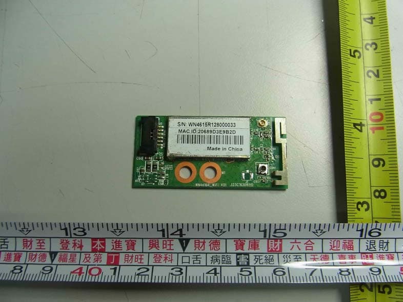
Click to zoom
Application Details
- Equipment Class
- DTS - Digital Transmission System
- Date of Grant
- Nov 06, 2012
- Application Purpose
- Original Equipment
- Date of Application
- Oct 23, 2012
- Equipment Note
- 802.11b/g/n 2T2R Wireless Lan USB Module
- Frequency Range
- 2412.00000000 - 2462.00000000
- Company
- LITE-ON TECHNOLOGY CORP.
- Country
- Taiwan
Documents & Files
Document Text
Text extracted from the exhibit documents filed with the FCC. Open a document above to read the original.
Users Manual
Ben J. Chen Page 1 11/7/2012 8 8 0 0 2 2 . . 1 1 1 1 n n 2 2 . . 4 4 G G 2 2 T T 2 2 R R W W i i r r e e l l e e s s s s L L A A N N U U S S B B M M o o d d u u l l e e W W N N 4 4 6 6 1 1 5 5 R R User’s Manual Ben J. Chen Page 2 11/7/2012 REGULATORY STATEMENTS FCC Certification The United States Federal Communication Commission (FCC) and the Canadian Department of Communications have established certain rules governing the use of electronic equipment. Part15, Class B This device complies with Part 15 of FCC rules. Operation is subject to the following two conditions: 1) This device may not cause harmful interference, and 2) This device must accept any interference received, including interference that may cause undesired operation. This equipment has been tested and found to comply with the limits for a Class B digital device, pursuant to Part15 of the FCC Rules. These limits are designed to provide reasonable protection against harmful interference in a residential installation. This equipment generates, uses and can radiate radio frequency energy, and if not installed and used in accordance with the instructions, may cause harmful interference to radio communications. However, there is no guarantee that interference will not occur in a particular installation. If this equipment does cause harmful interference to radio or television reception, which can be determined by turning off and on, the user is encouraged to try to correct the interference by one or more of the following measures: • Reorient or relocate the receiving antenna. • Increase the separation between the equipment and receiver. • Connect the equipment into an outlet on a circuit different from that to which the receiver is connected. • Consult the dealer or an experienced radio/TV technician for help. Ben J. Chen Page 3 11/7/2012 Warning: Changes or modifications to this unit not expressly approved by the party responsible for compliance could void the user authority to operate the equipment. 1. This Transmitter must not be co-located or operating in conjunction with any other antenna or transmitter. 2. For product available in the USA market, only channel 1~11 can be operated. Selection of other channels is not possible. IMPORTANT NOTE: This module is intended for OEM integrator. The OEM integrator is still responsible for the FCC compliance requirement of the end product, which integrates this module. 20cm minimum distance has to be able to be maintained between the antenna and the users for the host this module is integrated into. Under such configuration, the FCC radiation exposure limits set forth for an population/uncontrolled environment can be satisfied. Any changes or modifications not expressly approved by the manufacturer could void the user's authority to operate this equipment. USERS MANUAL OF THE END PRODUCT: In the users manual of the end product, the end user has to be informed to keep at least 20cm separation with the antenna while this end product is installed and operated. The end user has to be informed that the FCC radio-frequency exposure guidelines for an uncontrolled environment can be satisfied. The end user has to also be informed that any changes or modifications not expressly approved by the manufacturer could void the user's authority to operate this equipment. If the size of the end product is smaller than 8x10cm, then additional FCC part 15.19 statement is required to be available in the user manual: This device complies with Part 15 of FCC rules. Operation is subject to the following two conditions: (1) this device may not cause harmful interference and (2) this device must accept any interference received, including interference that may cause undesired operation. Ben J. Chen Page 4 11/7/2012 This Class B digital apparatus complies with Canadian ICES-003. Cet appareil numérique de la classe B conforme á la norme NMB-003 du Canada. Operation is subject to the following two conditions: (1) this device may not cause interference, and (2) this device must accept any interference, including interference that may cause undesired operation of the device. For product available in the USA/Canada market, only channel 1~11 can be operated. Selection of other channels is not possible. This device and its antenna(s) must not be co-located or operation in conjunction with any other antenna or transmitter. To reduce potential radio interference to other users, the antenna type and its gain should be so chosen that the equivalent isotropically radiated power (e.i.r.p) is not more than that permitted for successful communication. Ben J. Chen Page 5 11/7/2012 INTRODUCTION The 802.11b/g/n 2T2R USB WLAN Module is a device that allows you connect your computer to a wireless local area network (LAN). A wireless LAN allows your system to use wireless Radio Frequency (RF) technology to transmit and receive data without physically attaching to the network. The Wireless protocols that come with this product ensure data security and isolation from interference generated by other radio frequencies. This card also allows you to take full advantage of your computer’s mobility with access to real-time information and online services anytime and anywhere. In addition, this device eliminates the bother of pulling cable through walls and under furniture. It even allows you to place your system in locations where cabling is impossible. Modifying and augmenting networks has never been so easy. Wireless Network Options The Peer-to-Peer Network This network installation lets you set a small wireless workgroup easily and quickly. Equipped with wireless PC Cards or wireless PCI, you can share files and printers between each PC and laptop. You can also use one computer as an Internet Server to connect to a wired global network and share files and information with other computers via a wireless LAN. The Access Point Network The network installation allows you to share files, printers, and Internet access much more conveniently. …
Text truncated - open the document above for the full version.
Cover Letter(s)
RF_160, Issue 03 Declaration of Authorization We Name: LITE-ON TECHNOLOGY CORP. Address: 4F, 90, Chien 1 Road Chung Ho, New Taipei City, Tawian R.O.C. City: New Taipei City Country: Taiwan Declare that: Agent Company name: Neutron Engineering, Inc. Address: B1, No. 37, Lane 365, YangGuang St., NeiHu District 114, Taipei, Taiwan City: New Taipei City Country Taiwan is authorized to apply for Certification of the following product(s): Product description: 802.11b/g/n 2T2R Wireless Lan USB Module Type designation: WN4615R Trademark: LITEON on our behalf. Date: 2012.10.12 City: New Taipei City .. Name: TCWu.. (2) Function: Director......................... ...... Signature: . Notes: (1): Required for FCC application (2): For FCC it must be the Grantee Code “owner” or the authorized agent.
Cover Letter(s)
FCC, Request for non-disclosure Date: 16-Jul-10 RF_501, Issue 6 Page 1 of 1 Company Name: LITE-ON TECHNOLOGY CORP. Address: 4F, 90, Chien 1 Road Chung Ho, New Taipei City, Tawian R.O.C. City: New Taipei City Country: Taiwan To: Telefication B.V., Dept. FCC TCB Edisonstraat 12A 6902 PK ZEVENAAR The Netherlands Subject: Request for confidentiality FCC ID: PPQ-WN4615R Reference number: WN4615R Dear FCC TCB, 1. Long-Term Confidentiality Pursuant to 47 CFR Section 0.459(a) & (b), we hereby requests non-disclosure and confidential treatment of the following materials submitted in support of FCC certification application: Bill(s) of Material Block Diagrams Operational Description Schematic Diagrams Above materials contain secrets, proprietary and technical information, which would customarily be guarded from competitors under 47 CFR, section 0.457(d)(2). Disclosure or publication or any portion of this company confidential material to other parties could cause substantial competitive harm and provide unjustified benefits for competitors. 2. Short-Term Confidentiality (STC) Pursuant to Public Notice DA 04-1705 of the Commission’s policy, in order to comply with the marketing regulations in 47 CFR §2.803 and the importation rules in 47 CFR §2.1204, applicant hereby requests Short-Term Confidential treatment of the following materials (note 1): Internal Photos User’s Manual Test Set-up Photos External Photos Justification: Planned Release Date STC: (notes 2, 3, 4, 5) Date: 2012-10-12 Name and signature of applicant: TC Wu Notes: 1) A document or type of document can only have ONE type of confidentiality! 2) Short-Term confidentiality is in principle for 45 days from date of grant; it can be extended max 3 times (total time 180 days max.)! 3) FCC must be informed when marketing begins earlier. 4) Release takes place automatically thus extension must be requested in time. Telefication does not remind you of this! 5) Request for extension or for release must be received by Telefication at least 7 days before date of actual marketing or before expiration of the STC period
Cover Letter(s)
CERTIFICATE OF COMPLIANCE Report No.: NEI-FCCE-1-1210095 Issued Date: Oct. 17, 2012 Authorized under Declaration of Conformity according to 47 CFR, Part 2 and Part 15 of the FCC Rules. The product listed in follows was (were) tested in the Neutron EMC Laboratory to comply with the criteria limits Class B of conducted and radiated emissions of the Technical Standards FCC Part 15, Subpart B: 2010, established by the FCC, USA. Equipment 802.11b/g/n 2T2R Wireless Lan USB Module Model Name WN4615R Brand Name LITEON Applicant LITE-ON TECHNOLOGY CORP. Address 4F, 90, Chien 1 Road Chung Ho, New Taipei City, Taiwan R.O.C. Measurement ANSI C63.4: 2009 Method ICES-003 Issue 5: 2012 The test data, data evaluation, and equipment configuration contained in our test report (Report No. NEI-FCCE-1-1210095) were obtained utilizing the test procedures, test instruments, test sites that has been accredited by the Authority of NVLAP and TAF according to the ISO-17025 quality assessment standard and technical standard(s). The test data contained in the referenced test report relate only to the EUT sample and item(s) tested. Andy Chiu Authorized Signatory Neutron Engineering Inc. B1, No. 37, Lane 365, YangGuang St., NeiHu District 114, Taipei, Taiwan. TEL: +886-2-2657-3299 FAX: +886-2-2657-3331
Cover Letter(s)
RF_734_00, Issue 1 Modular Approval Request FCC (per DA 00-1407) FCC ID: PPQ-WN4615R Items to be covered Answer from applicant 1. The modular transmitter must have its own RF shielding. YES, please refer to EUT photo 2. The modular transmitter must have buffered modulation/data inputs (if such inputs are provided) to ensure that the module will comply with Part 15 requirements under conditions of excessive data rates or over-modulation. YES , module use U4 RT5372 as buffer modulation / data inputs 3. The modular transmitter must have its own power supply regulation. YES , Module use U7 for 5V- 3.3V as power supply regulation 4. The modular transmitter must comply with the antenna requirements of Section 15.203 and 15.204(c). The antenna must either be permanently attached or employ a “unique” antenna coupler (at all connections between the module and the antenna, including the cable).. YES, the antenna is employ a permanently attached (PIFA). Please refer to external photo. 5. The modular transmitter must be tested in a stand-alone configuration, i.e., the module must not be inside another device during testing. This is intended to demonstrate that the module is capable of complying with Part 15 emission limits regardless of the device into which it is eventually installed. YES, please refer to test photo 6. The modular transmitter must be labeled with its own FCC ID number, and, if the FCC ID is not visible when the module is installed inside another device, then the outside of the device into which the module is installed must also display a label referring to the enclosed module. This exterior label can use wording such as the following: “Contains Transmitter Module FCC ID: XYZMODEL1” or “Contains FCC ID: XYZMODEL1.” Any similar wording that expresses the same meaning may be used. The Grantee may either provide such a label, an example of which must be included in the application for equipment authorization, or, must provide adequate instructions along with the module which explain this requirement. In the latter case, a copy of these instructions must be included in the application for equipment authorization. YES, please refer to label 7. The modular transmitter must comply with any specific rule or operating requirements applicable to the transmitter and the manufacturer must provide adequate instructions along with the module to explain any such requirements. A copy of these instructions must be included in the application for equipment authorization. For example, there are very strict operational and timing requirements that must be met before a transmitter is authorized for operation under Section 15.231. For instance, data transmission is prohibited, except for operation under Section 15.231(e), in which case there are separate field strength level and timing requirements. Compliance with these requirements must be assured. YES, please refer to User manual 8. The modular transmitter must comply with any applicable RF exposure requirements. For example, FCC Rules in Sections 2.1091, 2.1093 and specific Sections of Part 15, including 15.319(i), 15.407(f), 15.253(f) and 15.255(g), require that Unlicensed PCS, UNII and millimeter wave devices perform routine environmental evaluation for RF Exposure to demonstrate compliance. In addition, spread spectrum transmitters operating under Section 15.247 are required to address RF Exposure compliance in accordance with Section 15.247(b)(4). Modular transmitters approved under other Sections of Part 15, when necessary, may also need to address certain RF Exposure concerns, typically by providing specific installation and operating instructions for users, installers and other interested parties to ensure compliance. YES, please refer RF Exposure test report Note: If compliance with one or more of the numbered requirements, listed above, cannot be demonstrated, it may be possible to obtain a “Limited Modular Approval” (LMA). Name and surname of applicant (or authorized representative): _TC Wu_ RF_734_00, Issue 1 Date: ____2012-10-23___ Signature:____ ______________________
External Photos
RV-0000000 Project No.: 1210095 Page 2 of 7 Neutron Engineering Inc. 1210095 1210095
Internal Photos
RV-0000000 Project No.: 1210095 Page 3 of 7 Neutron Engineering Inc. Antenna 1 1210095 1210095 Antenna 1 RV-0000000 Project No.: 1210095 Page 4 of 7 Neutron Engineering Inc. 1210095 RV-0000000 Project No.: 1210095 Page 5 of 7 Neutron Engineering Inc. Antenna 2 Antenna 3 1210095 1210095 RV-0000000 Project No.: 1210095 Page 6 of 7 Neutron Engineering Inc. Antenna 4 Antenna 5 1210095 1210095 RV-0000000 Project No.: 1210095 Page 7 of 7 Neutron Engineering Inc. Antenna 6 1210095
RF Exposure Info
RV-0000000 Report No.: NEI-FCCP-1-1210095 Page 157 of 169 Neutron Engineering Inc. 11 RF EXPOSURE COMPLIANCE 11.1 LIMIT Systems operating under the provisions of this section shall be operated in a manner that ensures that the public is not exposed to radio frequency energy levels in excess limit for maximum permissible exposure. In accordance with 47 CFR FCC Part 2 Subpart J, section 2.1091 this device has been defined as a mobile device whereby a distance of 0.2 m normally can be maintained between the user and the device. (A) Limits for Occupational / Controlled Exposure Frequency Range (MHz) Electric Field Strength (E) (V/m) Magnetic Field Strength (H) (A/m) Power Density (S) (mW/ cm 2 ) Averaging Time |E| 2 ,|H| 2 or S (minutes) 0.3-3.0 614 1.63 (100)* 6 3.0-30 1842 / f 4.89 / f (900 / f)* 6 30-300 61.4 0.163 1.0 6 300-1500 F/300 6 1500-100,000 5 6 (B) Limits for General Population / Uncontrolled Exposure Frequency Range (MHz) Electric Field Strength (E) (V/m) Magnetic Field Strength (H) (A/m) Power Density (S) (mW/ cm 2 ) Averaging Time |E| 2 ,|H| 2 or S (minutes) 0.3-1.34 614 1.63 (100)* 30 1.34-30 824/f 2.19/f (180/f)* 30 30-300 27.5 0.073 0.2 30 300-1500 F/1500 30 1500-100,000 1.0 30 NOTE: f = frequency in MHz ; *Plane-wave equivalent power density. 11.2 MEASUREMENT INSTRUMENTS LIST Item Kind of EquipmentManufacturer Type No. Serial No. Calibrated until 1 Power Meter Anritsu ML2495A 1128008 Feb,20,2013 2 Power Meter Sensor Anritsu MA2411B 1126001 Feb,20,2013 NOTE: N/A: denotes No Model Name, No Serial No. or No Calibration specified. 11.3 MPE CALCULATION METHOD E (V/m) = d GP××30 Power Density: Pd (W/m²) = 377 2 E E = Electric field (V/m) P = Peak RF output power (W) G = EUT Antenna numeric gain (numeric) d = Separation distance between radiator and human body (m) The formula can be changed to Pd = 2 377 30 d GP × ×× From the peak EUT RF output power, the minimum mobile separation distance, d=0.2m, as well as the gain of the used antenna, the RF power density can be obtained RV-0000000 Report No.: NEI-FCCP-1-1210095 Page 158 of 169 Neutron Engineering Inc. 11.4 TEST SETUP LAYOUT 11.5 DEVIATION FROM TEST STANDARD No deviation 11.6 EUT OPERATING CONDITIONS The EUT tested system was configured as the statements of 5.6 Unless otherwise a special operating condition is specified in the follows during the testing. RV-0000000 Report No.: NEI-FCCP-1-1210095 Page 159 of 169 Neutron Engineering Inc. 11.7 TEST RESULTS E.U.T 802.11b/g/n 2T2R Wireless Lan USB Module Model Name WN4615R Temperature 26°C Relative Humidity 60% Test Voltage AC 120V/60Hz Test Mode IEEE 802.11b/2412 MHz, 2437 MHz, 2462 MHz Frequency Antenna Gain (dBi) Antenna Gain (numeric) Peak Output Power (dBm) Peak Output Power ( mW ) Power Density (S) Limit of Power Density (S) Result 2412 MHz 4.11 2.5763 17.9500 62.3735 0.031985 1 PASS 2437 MHz 4.11 2.5763 17.6900 58.7489 0.030127 1 PASS 2462 MHz 4.11 2.5763 17.7600 59.7035 0.030616 1 PASS RV-0000000 Report No.: NEI-FCCP-1-1210095 Page 160 of 169 Neutron Engineering Inc. E.U.T 802.11b/g/n 2T2R Wireless Lan USB Module Model Name WN4615R Temperature 26°C Relative Humidity 60% Test Voltage AC 120V/60Hz Test Mode IEEE 802.11g/2412 MHz, 2437 MHz, 2462 MHz Frequency Antenna Gain (dBi) Antenna Gain (numeric) Peak Output Power (dBm) Peak Output Power ( mW ) Power Density (S) Limit of Power Density (S) Result 2412 MHz 4.11 2.5763 20.7400 118.5769 0.060807 1 PASS 2437 MHz 4.11 2.5763 21.0200 126.4736 0.064856 1 PASS 2462 MHz 4.11 2.5763 20.8400 121.3389 0.062223 1 PASS RV-0000000 Report No.: NEI-FCCP-1-1210095 Page 161 of 169 Neutron Engineering Inc. E.U.T 802.11b/g/n 2T2R Wireless Lan USB Module Model Name WN4615R Temperature 26°C Relative Humidity 60% Test Voltage AC 120V/60Hz Test Mode IEEE 802.11n (20 MHz)/ANT.1/2412 MHz, 2437 MHz, 2462 MHz Frequency Antenna Gain (dBi) Antenna Gain (numeric) Peak Output Power (dBm) Peak Output Power ( mW ) Power Density (S) Limit of Power Density (S) Result 2412 MHz 4.11 2.5763 21.2000 131.8257 0.067601 1 PASS 2437 MHz 4.11 2.5763 21.0400 127.0574 0.065155 1 PASS 2462 MHz 4.11 2.5763 21.0300 126.7652 0.065006 1 PASS RV-0000000 Report No.: NEI-FCCP-1-1210095 Page 162 of 169 Neutron Engineering Inc. E.U.T 802.11b/g/n 2T2R Wireless Lan USB Module Model Name WN4615R Temperature 26°C Relative Humidity 60% Test Voltage AC 120V/60Hz Test Mode IEEE 802.11n (20 MHz)/ANT.2/2412 MHz, 2437 MHz, 2462 MHz Frequency Antenna Gain (dBi) Antenna Gain (numeric) Peak Output Power (dBm) Peak Output Power ( mW ) Power Density (S) Limit of Power Density (S) Result 2412 MHz 5.31 3.3963 21.3600 136.7729 0.092459 1 PASS 2437 MHz 5.31 3.3963 21.7900 151.0080 0.102082 1 PASS 2462 MHz 5.31 3.3963 21.2700 133.9677 0.090563 1 PASS RV-0000000 Report No.: NEI-FCCP-1-1210095 Page 163 of 169 Neutron Engineering Inc. E.U.T 802.11b/g/n 2T2R Wireless Lan USB Module Model Name WN4615R Temperature 26°C Relative Humidity 60% Test Voltage AC 120V/60Hz Test Mode IEEE 802.11n (20 MHz)/ANT.Total/2412 MHz, 2437 MHz, 2462 MHz Frequency Antenna Gain (dBi) Antenna Gain (numeric) Peak Output Power (dBm) Peak Output Power ( mW ) Power Density (S) Limit of Power Density (S) Result 2412 MHz 9.42 8.7498 24.2910 268.5986 0.467793 1 PASS 2437 MHz 9.42 8.7498 24.4415 278.0654 0.484281 1 PASS 2462 MHz 9.42 8.7498 24.1620 260.7329 0.454094 1 PASS RV-0000000 Report No.: NEI-FCCP-1-1210095 Page 164 of 169 Neutron Engineering Inc. E.U.T 802.11b/g/n 2T2R Wireless Lan USB Module Model Name WN4615R Temperature 26°C Relative Humidity 60% Test Voltage AC 120V/60Hz Test Mode IEEE 802.11n (40 MHz)/ANT.1/2422 MHz, 2437 MHz, 2452 MHz Frequency Antenna Gain (dBi) Antenna Gain (numeric) Peak Output Power (dBm) Peak Output Power ( mW ) Power Density (S) Limit of Power Density (S) Result 2422 MHz 4.11 2.5763 19.6400 92.0450 0.047201 1 PASS 2437 MHz 4.11 2.5763 19.8700 97.0510 0.049768 1 PASS 2452 MHz 4.11 2.5763 19.8000 95.4993 0.048972 1 PASS RV-0000000 Report No.: NEI-FCCP-1-1210095 Page 165 of 169 Neutron Engineering I…
Text truncated - open the document above for the full version.
Test Report
RV-0000000 Report No.: NEI-FCCP-1-1210095 Page 1 of 169 Neutron Engineering Inc. Radio Test Report FCC ID: PPQ-WN4615R This report concerns (check one) : Original Grant Class II Change Issued Date : Oct. 17, 2012 Project No. : 1210095 Equipment : 802.11b/g/n 2T2R Wireless Lan USB Module Model Name : WN4615R Applicant : LITE-ON TECHNOLOGY CORP. Address : 4F, 90, Chien 1 Road Chung Ho, New Taipei City, Taiwan R.O.C. Tested by: Neutron Engineering Inc. EMC Laboratory Date of Receipt: Oct. 09, 2012 Date of Test: Oct. 09, 2012 ~ Oct. 16, 2012 Testing Engineer : (Gary Chou) Technical Manager : (Jeff Yang) Authorized Signatory : (Andy Chiu) Neutron Engineering Inc. B1, No. 37, Lane 365, YangGuang St., NeiHu District 114, Taipei, Taiwan. TEL: +886-2-2657-3299 FAX: +886-2-2657-3331 RV-0000000 Report No.: NEI-FCCP-1-1210095 Page 2 of 169 Neutron Engineering Inc. Declaration Neutron represents to the client that testing is done in accordance with standard procedures as applicable and that test instruments used has been calibrated with the standards traceable to National Measurement Laboratory (NML) of R.O.C., or National Institute of Standards and Technology (NIST) of U.S.A. Neutron's reports apply only to the specific samples tested under conditions. It is manufacture’s responsibility to ensure that additional production units of this model are manufactured with the identical electrical and mechanical components. Neutron shall have no liability for any declarations, inferences or generalizations drawn by the client or others from Neutron issued reports. Neutron’s reports must not be used by the client to claim product endorsement by the authorities or any agency of the Government. This report is the confidential property of the client. As a mutual protection to the clients, the public and Neutron-self, extracts from the test report shall not be reproduced except in full with Neutron’s authorized written approval. Neutron’s laboratory quality assurance procedures are in compliance with the ISO Guide 17025 requirements, and accredited by the conformity assessment authorities listed in this test report. Limitation For the use of the authority's logo is limited unless the Test Standard(s)/Scope(s)/Item(s) mentioned in this test report is (are) included in the conformity assessment authorities acceptance respective. RV-0000000 Report No.: NEI-FCCP-1-1210095 Page 3 of 169 Neutron Engineering Inc. Table of Contents REPORT ISSUED HISTORY 6 1 CERTIFICATION 7 2 . SUMMARY OF TEST RESULTS 8 2.1 TEST FACILITY 9 2.2 MEASUREMENT UNCERTAINTY 9 3 GENERAL INFORMATION 10 3.1 GENERAL DESCRIPTION OF EUT 10 3.2 DESCRIPTION OF TEST MODES 12 3.3 TABLE OF PARAMETERS OF TEXT SOFTWARE SETTING 13 3.4 BLOCK DIAGRAM SHOWING THE CONFIGURATION OF SYSTEM TESTED 14 3.5 DESCRIPTION OF SUPPORT UNITS 15 4 CONDUCTED EMISSION 16 4.1 LIMIT 16 4.2 MEASUREMENT INSTRUMENTS LIST 16 4.3 TEST PROCEDURES 17 4.4 TEST SETUP LAYOUT 17 4.5 DEVIATION FROM TEST STANDARD 17 4.6 EUT OPERATING CONDITIONS 18 4.7 TEST RESULTS 19 5 ANTENNA CONDUCTED SPURIOUS EMISSION 21 5.1 LIMIT 21 5.2 MEASUREMENT INSTRUMENTS LIST 21 5.3 TEST PROCEDURES 21 5.4 TEST SETUP LAYOUT 21 5.5 DEVIATION FROM TEST STANDARD 21 5.6 EUT OPERATING CONDITIONS 21 5.7 TEST RESULTS 22 6 6 DB BANDWIDTH 46 6.1 LIMIT 46 6.2 MEASUREMENT INSTRUMENTS LIST 46 6.3 TEST PROCEDURES 46 6.4 TEST SETUP LAYOUT 46 6.5 DEVIATION FROM TEST STANDARD 46 6.6 EUT OPERATING CONDITIONS 46 6.7 TEST RESULTS 47 7 MAXIMUM PEAK CONDUCTED OUTPUT POWER 59 7.1 LIMIT 59 7.2 MEASUREMENT INSTRUMENTS LIST 59 RV-0000000 Report No.: NEI-FCCP-1-1210095 Page 4 of 169 Neutron Engineering Inc. Table of Contents 7.3 TEST PROCEDURES 59 7.4 TEST SETUP LAYOUT 59 7.5 DEVIATION FROM TEST STANDARD 59 7.6 EUT OPERATING CONDITIONS 59 7.7 TEST RESULTS 60 8 RADIATED SPURIOUS EMISSION (9 KHZ TO 1 GHZ) 68 8.1 LIMIT 68 8.2 MEASUREMENT INSTRUMENTS LIST 69 8.3 MEASURING INSTRUMENTS SETTING 69 8.4 TEST PROCEDURES 70 8.5 DEVIATION FROM TEST STANDARD 70 8.6 TEST SETUP LAYOUT 70 8.7 EUT OPERATING CONDITIONS 71 8.8 TEST RESULTS 72 9 RADIATED SPURIOUS EMISSION (ABOVE 1 GHZ) 74 9.1 LIMIT 74 9.2 MEASUREMENT INSTRUMENTS LIST 75 9.3 MEASURING INSTRUMENTS SETTING 75 9.4 TEST PROCEDURES 76 9.5 DEVIATION FROM TEST STANDARD 76 9.6 TEST SETUP LAYOUT 76 9.7 EUT OPERATING CONDITIONS 77 9.8 TEST RESULTS 78 9.9 TEST RESULTS (RESTRICTED BANDS) 126 10 POWER SPECTRAL DENSITY 142 10.1 LIMIT 142 10.2 MEASUREMENT INSTRUMENTS LIST 142 10.3 TEST PROCEDURES 142 10.4 TEST SETUP LAYOUT 142 10.5 DEVIATION FROM TEST STANDARD 142 10.6 EUT OPERATING CONDITIONS 142 10.7 TEST RESULTS 143 11 RF EXPOSURE COMPLIANCE 157 11.1 LIMIT 157 11.2 MEASUREMENT INSTRUMENTS LIST 157 11.3 MPE CALCULATION METHOD 157 11.4 TEST SETUP LAYOUT 158 11.5 DEVIATION FROM TEST STANDARD 158 RV-0000000 Report No.: NEI-FCCP-1-1210095 Page 5 of 169 Neutron Engineering Inc. Table of Contents 11.6 EUT OPERATING CONDITIONS 158 11.7 TEST RESULTS 159 12 EUT TEST PHOTO 167 RV-0000000 Report No.: NEI-FCCP-1-1210095 Page 6 of 169 Neutron Engineering Inc. REPORT ISSUED HISTORY Revised Version No. Description Issued Date - Initial Issue. Oct. 17, 2012 RV-0000000 Report No.: NEI-FCCP-1-1210095 Page 7 of 169 Neutron Engineering Inc. 1 CERTIFICATION E q u i p m e n t : 802.11b/g/n 2T2R Wireless Lan USB Module Brand Name : LITEON Model Name : WN4615R A p p l i c a n t : LITE-ON TECHNOLOGY CORP. Date of Test : Oct. 09, 2012 ~ Oct. 16, 2012 Standards : FCC Part 15, Subpart C: 2010 ANSI C63.4: 2009 The above equipment has been tested and found compliance with the requirement of the relative standards by Neutron Engineering Inc. EMC Laboratory. The test data, data evaluation, and equipment configuration contained in our test report (Ref No. NEI-FCCP-1-1210095) were obtained utilizing the test procedures, test instruments, test sites that has been accredited by the Authority of NVLAP and TAF according to the ISO-17025 quality assessment standard and technical standard(s). RV-0000000 Report No.: NEI-FCCP-1-1210095 Page 8 of 169 …
Text truncated - open the document above for the full version.
Test Setup Photos
RV-0000000 Report No.: NEI-FCCP-1-1210095 Page 167 of 169 Neutron Engineering Inc. 12 EUT TEST PHOTO Conducted emission test photos 1210095 1210095 RV-0000000 Report No.: NEI-FCCP-1-1210095 Page 168 of 169 Neutron Engineering Inc. Radiated spurious emission test photos Below 1 GHz 1210095 1210095 RV-0000000 Report No.: NEI-FCCP-1-1210095 Page 169 of 169 Neutron Engineering Inc. Radiated spurious emission test photos Above 1 GHz 1210095 1210095
Contact Information
Applicant
TC Wu(Deputy Director(R & D Division))
Technical Contact
Neutron Engineering Inc.Kate Lin
[email protected]886-2-2657-3299
B1, No. 37, Lane 365, YangGang St., · Taiwan
Non-Technical Contact
Neutron Engineering Inc.Kate Lin
Test Firm
BTL Inc.Andy Yeh
Technical Specifications
| # | Rule Parts | Frequency Range | Power Output |
|---|---|---|---|
| 1 | 15C | 2.41 GHz - 2.46 GHz | 280.00 mW |
Other Applications from LITE-ON TECHNOLOGY CORP.
PPQ-WPB8326
Sep 05, 2025Indoor Wi-Fi 7 2x2 Tri-Band Enterprise Access Point
Equipment Class
6ID - 15E 6 GHz Low Power Indoor Access Point
PPQ-WCBN3605L
Aug 30, 2023802.11b/g/n 1Tx1R + BT5.0 IOT Combo Module
Equipment Class
DTS - Digital Transmission System
PPQ-WCBN3610L
Jul 24, 2023802.11 b/g/n, 1T1R 2.4G Wireless IoT Module
Equipment Class
DTS - Digital Transmission System
PPQ-WPX8324
Jan 30, 2023Access Point
Equipment Class
DTS - Digital Transmission System
PPQ-WM6321
Dec 16, 2021WM6321
Equipment Class
NII - Unlicensed National Information Infrastructure TX