PPQ-WP310AWIRELESS ACCESS POINT
LITE-ON TECHNOLOGY CORP.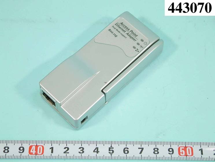
Click to zoom
Application Details
- Equipment Class
- DTS - Digital Transmission System
- Date of Grant
- Jun 23, 2004
- Application Purpose
- Original Equipment
- Date of Application
- Jun 23, 2004
- Equipment Note
- WIRELESS ACCESS POINT
- Frequency Range
- 2412.00000000 - 2462.00000000
- Company
- LITE-ON TECHNOLOGY CORP.
- Country
- Taiwan
Documents & Files
Document Text
Text extracted from the exhibit documents filed with the FCC. Open a document above to read the original.
Users Manual
Wireless Access Point / Ethernet Bridge Model Name: WP310A Quick Install Guide Hardware Installation Making a Connection 1. RJ45 port connects to a hub/switch or PC - Use a standard Ethernet RJ-45 cable. 2. Check the LED of “LAN” port on front panel, it must be on. If not, to ensure that the cable is connected properly. 3. Connect the power adapter to “DC 5V”. Attention: z The cable distance between the Router and PC/hub/Switch should not exceed 100 meters. z Make sure the wiring is correct. In 10Mbps operation, Category 3/4/5 cable can be used for connection. To reliably operate your network at 100Mbps, you must use Category 5 cable, or better Data Grade. Software Installation Before Setup... Verify the IP address setting You need to configure your PC’s network settings to obtain an IP address. Computer use IP addresses to communicate with each other across a network, such as the Internet. 1. From the taskbar, click the Start button, select Settings > Control Panel. From there, double-click the Network connections icon. 2. Right click the Local Area Connection icon Properties; select the TCP/IP line for the applicable Ethernet adapter. Then, click the Properties button. 3. Click the IP Address tab page, select USE the following IP address, type 192.168.1.1 ~ 192.168.1.254 ( but, 192.168.1.20 for the device use) in the IP Address field and 255.255.255.0 in the Subnet Mask field, then click OK button. Start Setup... 1. After getting the correct connection, start the web browser (make sure you disable the proxy) and type 192.168.1.20 in the Address field. Press Enter. 2. Enter the factory default User name and Password fields: User Name: Admin Password: 5up then click OK button. 3. You will enter the Utility homepage. Wireless Configuration - AP Mode After login Web UI, you can click “Access Point Web Server” to get into main configuration page. Main page will show 2.4GHz statistics automatically, you may click “Configuration” to modify system setting. Now you entered system configuration page, you can modify system default IP address right here. Please click “Radio” to modify wireless settings. WP310 default works in Access Point mode. You can change detail wireless parameters by clicking “Edit 2.4GHz Radio Settings” System default SSID is “Atheros_Wireless_Network”. You can modify SSID / Wireless Mode / Radio Frequency at this page Here is an example that we change SSID to “MyESS” and click “Update”. Then the page will show a “Reboot AP” bottom. You will need to click “Reboot AP” bottom and have the AP reboot to make the new setting start to function. Wireless Configuration – Ethernet Bridge Mode WP310A can also work as an Ethernet client bridge to connect Ethernet device into wireless network. In order to setup the AP to work in Ethernet bridge mode, you need to choose “Wireless Client” mode and click “Site Survey” at Radio page. The Site Survey page can help you identify all the APs currently working in your environment. You will have to remember the SSID you are going to join. After you determine which AP (SSID) to join, you need to go back to “Edit 2.4GHz Radio Settings” page. Key in “SSID” column with the value you get from site survey page and press “Update” bottom then reboot AP. After the AP reboot, new Ethernet Bridge setting will in effective immediately. From the 2.4GHz Statistics page, you can find that the WP310A works as a client (STA) and associated to the AP you specified. FEDERAL COMMUNICATIONS COMMISSION This device complies with Part 15 of the FCC Rules. Operation is subject to the following two conditions:(1) this device may not cause harmful interference, and (2) this device must accept any interference received, including interference that may cause undesired operation. Changes or modifications not expressly approved by the party responsible for compliance could void the user‘s authority to operate the equipment. NOTE This equipment has been tested and found to comply with the limits for a Class B digital device, pursuant to Part 15 of the FCC Rules. These limits are designed to provide reasonable protection against harmful interference in a residential installation. This equipment generates, uses and can radiated radio frequency energy and, if not installed and used in accordance with the instructions, may cause harmful interference to radio communications. However, there is no guarantee that interference will not occur in a particular installation If this equipment does cause harmful interference to radio or television reception, which can be determined by turning the equipment off and on, the user is encouraged to try to correct the interference by one or more of the following measures: -Reorient or relocate the receiving antenna. -Increase the separation between the equipment and receiver. -Connect the equipment into an outlet on a circuit different from that to which the receiver is connected. -Consult the dealer or an experienced radio/TV technician for help. Note: This device and its antenna(s) used for this transmitter must not be co-located or operating in conjunction with any other antenna or transmitter. This equipment complies with FCC radiation exposure limits set forth for an uncontrolled environment. In order to avoid the possibility of exceeding the FCC radio frequency exposure limits, human proximity to the antenna shall not be less than 20cm (8 inches) during normal operation.
External Photos
APPENDIX A. Photographs of EUT
ID Label/Location Info
FCC ID: PPQWP310A Label Location
Internal Photos
REPORT NO. : F443070 SPORTON International Inc. PAGE NUMBER : A1 OF A1 TEL : 886-2-2696-2468 ISSUED DATE : May 27, 2004 FAX : 886-2-2696-2255 REPORT NO. : F443070 SPORTON International Inc. PAGE NUMBER : A2 OF A2 TEL : 886-2-2696-2468 ISSUED DATE : May 27, 2004 FAX : 886-2-2696-2255 REPORT NO. : F443070 SPORTON International Inc. PAGE NUMBER : A3 OF A3 TEL : 886-2-2696-2468 ISSUED DATE : May 27, 2004 FAX : 886-2-2696-2255 REPORT NO. : F443070 SPORTON International Inc. PAGE NUMBER : A4 OF A4 TEL : 886-2-2696-2468 ISSUED DATE : May 27, 2004 FAX : 886-2-2696-2255 REPORT NO. : F443070 SPORTON International Inc. PAGE NUMBER : A5 OF A5 TEL : 886-2-2696-2468 ISSUED DATE : May 27, 2004 FAX : 886-2-2696-2255 REPORT NO. : F443070 SPORTON International Inc. PAGE NUMBER : A6 OF A6 TEL : 886-2-2696-2468 ISSUED DATE : May 27, 2004 FAX : 886-2-2696-2255 REPORT NO. : F443070 SPORTON International Inc. PAGE NUMBER : A7 OF A7 TEL : 886-2-2696-2468 ISSUED DATE : May 27, 2004 FAX : 886-2-2696-2255 REPORT NO. : F443070 SPORTON International Inc. PAGE NUMBER : A8 OF A8 TEL : 886-2-2696-2468 ISSUED DATE : May 27, 2004 FAX : 886-2-2696-2255 REPORT NO. : F443070 SPORTON International Inc. PAGE NUMBER : A9 OF A9 TEL : 886-2-2696-2468 ISSUED DATE : May 27, 2004 FAX : 886-2-2696-2255
Operational Description
FCC ID: PPQWP310A Description of Operation EUT is a 802.11b/g Wireless Access Point / Ethernet Bridge with 11 channels. This device provided a convergence procedure for the 2, 5.5, and 11 Mbps mandatory 802.11b modes, and the optional CCK-OFDM modes at 6, 9, 12, 18, 24, 36, 48, and 54Mbit/s specification in which PSDUs are converted to and from PPDUs. The device adapts Direct Sequence Spread Spectrum (DSSS) and Orthogonal Frequency Division Multiplexing (OFDM) modulation. The antenna is Dipole Antenna, and there is no external connector. This 802.11b/g Wireless Access Point / Ethernet Bridge is an IEEE 802.11b/g Wireless LAN adapter. It allows your computer to connect to a wireless network and to share resources, such as files or printers without being bound to the network wires. Operation in 2.4GHz Direct Sequence Spread Spectrum (DSSS) and Orthogonal Frequency Division Multiplexing (OFDM) radio transmission, the 802.11b/g PCI adapter card transfers data at speeds up to 64/128-bit Wired Equivalent Protection (WEP) algorithm is used. In addition, its standard compliance ensures that it can communicate with any 802.11g network.
Test Report
FCC ID: PPQ-WP310A Issued on May 26, 2004 Report No.: F443070 SPORTON International Inc. TEL : 886-2-2696-2468 FAX : 886-2-2696-2255 FCC TEST REPORT CATEGORY : Mobile End Product PRODUCT NAME : Wireless Access Point / Ethernet Bridge FCC ID. : PPQ-WP310A FILING TYPE : Certification BRAND NAME : LITE-ON, Pro-Nets, SpeedCom+, NetoDragon, TRANSGEAR MODEL NAME : LWP3120, WP-310A, AP54GA, BA-100 APPLICANT : LITE-ON TECHNOLOGY CORP. 2F, No. 6, Lane 359, Sec.2, Chung-Shan Rd., Chung-Ho, Taiwan, R.O.C. MANUFACTURER : G-COM COMPUTER CORPORATION 1 st Row Yin Shan Rd., Yin Hwu Industrial Area, Qingxi Town, Dong Guan City, Guang Dong, China ISSUED BY : SPORTON INTERNATIONAL INC. 6F, No. 106, Sec. 1, Hsin Tai Wu Rd., His Chih, Taipei Hsien, Taiwan, R.O.C. Statements: The test result in this report refers exclusively to the presented test model / sample. Without written approval of SPORTON International Inc., the test report shall not be reproduced except in full. Certificate or Test Report could not be used by the applicant to claim the product endorsement by CNLA, NVLAP or any agency of U.S. government. The test equipment used to perform the test are calibrated and traceable to NML/ROC or NIST/USA. Dr. Alan Lane Vice General Manager Sporton International Inc. Lab Code: 200079-0 1190 ILAC MRA FCC ID: PPQ-WP310A Issued on May 26, 2004 Report No.: F443070 SPORTON International Inc. FCC ID. : PPQ-WP310A TEL : 886-2-2696-2468 Page No. : i FAX : 886-2-2696-2255 Issued Date : May 26, 2004 Table of Contents History of this test report....................................................................................................................................ii 1. General Description of Equipment under Test.............................................................................................1 1.1. Applicant..........................................................................................................................................................................................1 1.2. Manufacturer ...................................................................................................................................................................................1 1.3. Basic Description of Equipment under Test ....................................................................................................................................1 1.4. Features of Equipment under Test..................................................................................................................................................1 1.5. Table for Carrier Frequencies .........................................................................................................................................................2 2. Test Configuration of the Equipment under Test.........................................................................................3 2.1. Description of the Test ....................................................................................................................................................................3 2.2. Frequency Range Investigated .......................................................................................................................................................3 2.3. Description of Test Supporting Units...............................................................................................................................................4 2.4. Connection Diagram of Test System ..............................................................................................................................................5 2.5. Test Software ..................................................................................................................................................................................6 3. Test Location and Standards .........................................................................................................................7 3.1. Test Location...................................................................................................................................................................................7 3.2. Test Conditions ...............................................................................................................................................................................7 3.3. Standards for Methods of Measurement .........................................................................................................................................7 3.4. DoC Statement................................................................................................................................................................................7 4. List of Measurements......................................................................................................................................8 4.1. Summary of the Test Results ..........................................................................................................................................................8 5. Test Result .......................................................................................................................................................9 5.1. Test of 6dB Spectrum Bandwidth ( DSSS System ) .......................................................................................................................9 5.2. Test of Maximum Peak Output Power ..........................................................................................................................................14 5.3. Test of Peak Power Spectral Density............................................................................................................................................16 5.4. Test of Band Edges Emission ............................................................................................................................…
Text truncated - open the document above for the full version.
Contact Information
Applicant
TC Wu(Deputy Director(R & D Division))
Test Firm
SPORTON International IncKathy Lin
Technical Specifications
| # | Rule Parts | Frequency Range | Power Output |
|---|---|---|---|
| 1 | 15C | 2.41 GHz - 2.46 GHz | 77.98 mW |
Other Applications from LITE-ON TECHNOLOGY CORP.
PPQ-WPB8326
Sep 05, 2025Indoor Wi-Fi 7 2x2 Tri-Band Enterprise Access Point
Equipment Class
6ID - 15E 6 GHz Low Power Indoor Access Point
PPQ-WCBN3605L
Aug 30, 2023802.11b/g/n 1Tx1R + BT5.0 IOT Combo Module
Equipment Class
DTS - Digital Transmission System
PPQ-WCBN3610L
Jul 24, 2023802.11 b/g/n, 1T1R 2.4G Wireless IoT Module
Equipment Class
DTS - Digital Transmission System
PPQ-WPX8324
Jan 30, 2023Access Point
Equipment Class
DTS - Digital Transmission System
PPQ-WM6321
Dec 16, 2021WM6321
Equipment Class
NII - Unlicensed National Information Infrastructure TX