PQRDS540-MPCI6Wireless LAN MiniPCI Card
Contec Co., Ltd.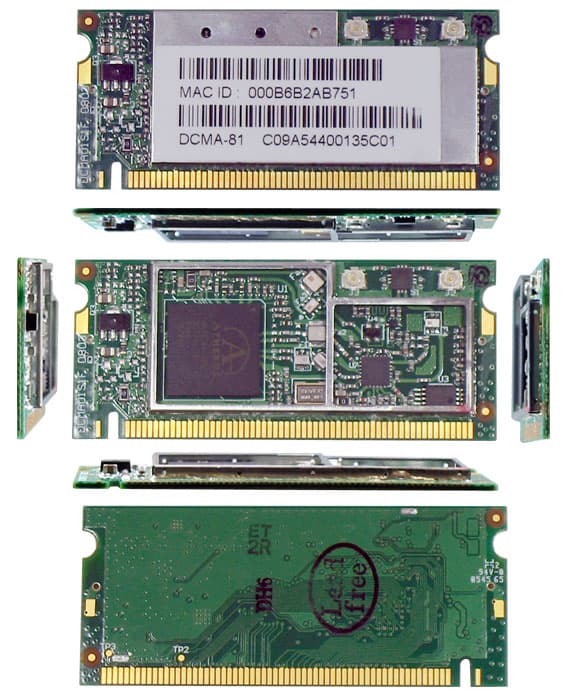
Click to zoom
Application Details
- Equipment Class
- NII - Unlicensed National Information Infrastructure TX
- Date of Grant
- Mar 28, 2006
- Application Purpose
- Original Equipment
- Date of Application
- Mar 28, 2006
- Equipment Note
- Wireless LAN MiniPCI Card
- Frequency Range
- 5745.00000000 - 5805.00000000
- Company
- Contec Co., Ltd.
- Country
- Japan
Documents & Files
Document Text
Text extracted from the exhibit documents filed with the FCC. Open a document above to read the original.
Users Manual
IEEE802.11a/b/g Wireless LAN MiniPCI Module FX-DS540-MPCI6 User’s Manual (Installation Manual) CONTEC CO., LTD. Chapter 1: General Description This document contains the specifications pertinent to the wireless LAN module (FX-DS540-MPCI6), which comply with IEEE802.11a, IEEE802.11b and IEEE802.11g. FX-DS540-MPCI6 is used attaching in the wireless LAN access point. Features 2.4GHz Wireless LAN module ・ IEEE802.11b and IEEE802.11g compatible ・ BPSK, QPSK, CCK, and DSSS modulation schemes supported Data rates 1, 2, 5.5 and 11Mbps ・ BPSK, QPSK, 16QAM, 64QAM and OFDM modulation schemes supported Data rate 6, 9, 12, 18, 24, 36, 48 and 54Mbps ・ Coax. RF connectors: HIROSE U.FL equivalent 5GHz Wireless LAN module ・ IEEE802.11a compatible ・ BPSK, QPSK, 16QAM, 64QAM and OFDM modulation schemes supported Data rate 6, 9, 12, 18, 24, 36, 48 and 54Mbps ・ Coax. RF Connectors : HIROSE U.FL equivalent System Functions ・ Low power sleep mode control ・ MiniPCI Interface ・ Radio circuit ON/OFF (RF Disable) Chapter 2: Characteristics Table1: Mechanical Characteristics Dimensions 31.3 x 59.6 x 2.4 (mm) Weight 10g Figure1: FX-DS540-MPCI6 25.5 59.6 (mm) Table2: Electrical Characteristics Supply voltage Vcc Nominal : 3.3V Extreme : 3.3V +/- 10% Storage temperature Humidity -20 to 80 deg.C 10 to 90 Operating Temperature Humidity 0 to 70 deg.C 10 to 90%no-condensing) Chapter 3: Setup FX-DS540-MPCI6 is used attaching in the wireless LAN access point. The wireless LAN access point is restricted only to CONTEC products. As an example, the case where it attaches in FX-DS540-STB-NR52 is introduced. Attach a coaxial cable and fix. (2 places) Coaxial cable: U.FL-2LP-04N1-A-(80) (HIROSE) Fix with a screw lock. (2places) Figure2: How to attach in FX-DS540-STB-NR52 - - - Chapter 4: Notes When FX-DS540-MPCI6 is installed in the wireless LAN access point, the following remarks are to be considered: 1. FX-DS540-MPCI6 is designated its own FCC ID Number: PQRDS540-MPCI6 and IC Number:4564A-MPCI6; therefore, the FCC ID and IC Number should be appeared on the label on the exterior of the wireless LAN access point unless it is visible from outside. Such label on the exterior should include a statement, either “Contains Wireless LAN Module FCC ID: PQRDS540-MPCI6, IC Number: 4564A-MPCI6” or “Contains FCC ID: PQRDS540-MPCI6, IC Number: 4564A-MPCI6”. 2. FX-DS540-MPCI6 is in compliance with the requirements of sub-sections 15.203, 15.205, 15.207, 15.209, 15.247 and 15.407 of FCC Rules Part 15. FX-DS540-MPCI6 is to be installed in accordance with their requirements. 3. User Manual of the wireless LAN access point, in which is FX-DS540-MPCI6 installed, will include the following statements required by FCC. - FCC WARNING: Changes or modifications not expressly approved by the party responsible for compliance could void the user’s authority to operate the equipment - This device complies with Part 15 of the FCC Rules and RSS-Gen of the IC Rules. Operation is subject to the following two conditions: (1) this device may not cause harmful interference, and (2) this device must accept any interference received, including interference that may cause undesired operation. In according with 47 CFR Part15.407 (e) U-NII devices operating in 5.15-5.25GHz frequency bands are restricted to indoor operations only. This transmitter must not be co-located or operated in conjunction with any other antenna or transmitter. This equipment complies with FCC radiation exposure limits set forth for uncontrolled equipment and meets the FCC radio frequency (RF) Exposure Guidelines in Supplement C to OET65. This equipment should be installed and operated with at least 20cm and more between the radiator and person’s body (excluding extremities: hands, wrists, feet and legs). 4. The installers must ensure that the public is not exposed to radio frequency energy levels in excess of FCC guidelines in accordance with FCC Rules: Part 15 and FCC OET Bulletin 65, Supplement C. 5. The installer of this radio equipment must ensure that antenna is located or pointed such that it does not emit RF field in excess of Health Canada limits for the general population; consult Safety Code 6, obtainable from Health Canada's website www.hc-sc.gc.ca/rpb 6. This class A digital apparatus complies with Canadian ICES-003. Cet appareil numérique de la classe A est conforme à la norme NMB-003 du Canada.
Cover Letter(s)
FCC ID : PQRDS540-MPCI6 Date: March 20, 2006 Model : FX-DS540-MPCI6 Applicant : CONTEC CO., LTD. Request for Limited Modular Approval The Wireless LAN MiniPCI Module (Model: FX-DS540-MPC16) is designed by CONTEC CO., LTD. This modular transmitter will be equipped and used only for host device such as measuring equipment which can supply regulate power of 3.3V stably. The modular transmitter complies the module basic requirement (Item 1 to 8) in FCC Public Notice: Part 15 Unlicensed Modular Transmitter Approval (DA00-1407) as indicated below. [Module basic requirement] (1) Have its own RF shielding: This modular transmitter has it own RF shielding. Please refer to the following Photo; (2) The modular transmitter must have buffered modulation/data inputs: Data input to this modular transmitter is controlled as not generating excessive data speed and abnormal modulation. (3) The modular transmitter must have its own power supply regulation: The modular transmitter has two regulators. DC3.3V from MINI PCI Bus is regulated to DC 2.5V and DC1.8V. DC2.5V and DC3.3V are supplied to radio part. DC 1.8V and DC 3.3V are supplied to MAC Controller. Therefore, the modular transmitter meets the requirement. (4) The modular transmitter must comply with the antenna requirements of Section 15.203, 15.204(c) and 15.407(d): Unique coupling (antenna connector, Type: AYU1) is used for the modular transmitter. (5) The modular transmitter must be tested in a stand alone: The test has been performed as a stand alone. Please refer to the test report. (6) The modular transmitter must be labeled with its own FCC ID, and, if the FCC ID are not visible when the module is installed inside another device, then the outside of the device into which the module is installed must also display a label referring to the enclosed module: This modular transmitter is complied with this requirement. Please refer to the Label drawing and location. In addition, the final product will display FCC ID of the module, if it is installed inside. (7) The modular transmitter must comply with any specific rule or operating requirements applicable to the transmitter and the manufacturer must provide adequate instructions along with the module to explain any such requirements: The necessary explanation to be complied with this requirement is contained in the manual. (8) The modular transmitter must comply with any applicable RF exposure requirements: Please refer to the RF exposure statement. Naoki Ikeda Assistant Leader Product Engineering Sec. Quality Assurance Div. RF shielding
RF Exposure Info
Applicant: CONTEC CO., LTD. Type of Equipme nt: Wire le s s LAN M iniPCI Card Model No. : FX-DS540-MPCI6 FCC ID: PQRDS540-M PCI6 CONTEC CO., LTD. declares that Model : Wireless LAN MiniPCI Card complies with FCC radiation exposure requirement specified in the FCC Rules 2.1093(for portable)/2.1091 (for mobile). The “FX-DS540-MPCI6“ has 25.59 mW of conducted Peak Output power and 51.05 mW of EIRP. This kind of equipment is below 60/frequency[GHz] mW(TCB Exclusion List) so that SAR testing is excluded. The Following calculation is the reference data for 20cm distance. RF Expos ure Calculations : The following information provides the minimum separation distance for the highest gain antenna provided with the “FX-DS540-MPCI6“ as calculated from FCC OET Bulletin 65 Appendix A, Table (B) Limits for General Population / Uncontrolled Exposure. This calculation is based on the highest EIRP possible from the system, considering maximum power and antenna gain, and considering a 1.0mW/cm^2 uncontrolled exposure limit. The Friis formula used was: S = (P * G) / (4* π * r 2 ) Whe re P =2 5 . 5 9 mW (M a x imum pe a k o utput po we r) G =2.00 Numerical Antenna gain; equal to3.00 dBi r =20.0 cm For: FX-D S540-M PCI6S = 0.01016 mW/c m 2 No. : 26FE0180-HO RF Exposure / SAR Statement Applicant: CONTEC CO., LTD. Type of Equipme nt: Wire le s s LAN M iniPCI Card Model No. : FX-DS540-MPCI6 FCC ID: PQRDS540-M PCI6 CONTEC CO., LTD. declares that Model : Wireless LAN MiniPCI Card complies with FCC radiation exposure requirement specified in the FCC Rules 2.1093(for portable)/2.1091 (for mobile). The “FX-DS540-MPCI6“ has 194.54 mW of conducted Peak Output power and 308.32 mW of EIRP. This kind of equipment is below 60/frequency[GHz] mW(TCB Exclusion List) so that SAR testing is excluded. The Following calculation is the reference data for 20cm distance. RF Expos ure Calculations : The following information provides the minimum separation distance for the highest gain antenna provided with the “FX-DS540-MPCI6“ as calculated from FCC OET Bulletin 65 Appendix A, Table (B) Limits for General Population / Uncontrolled Exposure. This calculation is based on the highest EIRP possible from the system, considering maximum power and antenna gain, and considering a 1.0mW/cm^2 uncontrolled exposure limit. The Friis formula used was: S = (P * G) / (4* π * r 2 ) Whe re P =194.54 mW (Maximum peak output power) G =1.58 Numerical Antenna gain; equal to2.00 dBi r =20.0 cm For: FX-D S540-M PCI6S = 0.06134 mW/c m 2 No. : 26FE0180-HO RF Exposure / SAR Statement
Test Report
Test report No. : 26FE0180-HO-5 Page : 1 of 70 Issued date : March 24, 2006 FCC ID : PQRDS540-MPCI6 UL Apex Co., Ltd. Head Office EMC Lab. 4383-326 Asama-cho, Ise-shi, Mie-ken 516-0021 JAPAN Telephone : +81 596 24 8116 Facsimile : +81 596 24 8124 MF060b(01.06.05) EMI TEST REPORT Test Report No. : 26FE0180-HO-5 Applicant : CONTEC CO., LTD. Type of Equipment : Wireless LAN MiniPCI Card Model No. : FX-DS540-MPCI6 Test standard : FCC Part 15 Subpart E Section 15.407 : 2006 FCC ID : PQRDS540-MPCI6 Test Result : Complied 1. This test report shall not be reproduced in full or partial, without the written approval of UL Apex Co., Ltd. 2. The results in this report apply only to the sample tested. 3. This equipment is in compliance with above regulation. We hereby certify that the data contain a true representation of the EMC profile. 4. The test results in this report are traceable to the national or international standards. Date of test: ______________________________ Tested by : ______________________________ ______________________________ Hiroka Umeyama EMC Services Kenichi Adachi EMC Services Approved by : ______________________________ Naoki Sakamoto Group Leader of EMC Services February 14 to 28, 2006 Test report No. : 26FE0180-HO-5 Page : 2 of 70 Issued date : March 24, 2006 FCC ID : PQRDS540-MPCI6 UL Apex Co., Ltd. Head Office EMC Lab. 4383-326 Asama-cho, Ise-shi, Mie-ken 516-0021 JAPAN Telephone : +81 596 24 8116 Facsimile : +81 596 24 8124 MF060b(01.06.05) CONTENTS PAGE SECTION 1: Client information ............................................................................................................ 3 SECTION 2: Equipment under test (E.U.T.)........................................................................................ 3 SECTION 3: Test specification, procedures & results......................................................................... 4 SECTION 4: Operation of E.U.T. during testing .................................................................................6 SECTION 5: Conducted Emission......................................................................................................... 8 SECTION 6: Spurious Emission , Band Edge Compliance ................................................................. 9 SECTION 7: 26dB Emission Bandwidth.............................................................................................10 SECTION 8: Peak Transmit Power..................................................................................................... 10 SECTION 9: Peak Power Spectral Density.........................................................................................10 SECTION 10: Peak Excursion Ratio ................................................................................................... 10 APPENDIX 1: Photographs of test setup ............................................................................................ 11 Conducted Emission ................................................................................................................................. 11 Spurious Emission (Radiated:below 1GHz) ...........................................................................................12 Spurious Emission (Radiated:above 1GHz) ...........................................................................................13 Worst Case Position (X-axis:Horizontal / Z-axis:Vertical)....................................................................14 APPENDIX 3: Data of EMI test............................................................................................................ 15 Conducted Emission .................................................................................................................................15 26dB Emission Bandwidth .......................................................................................................................25 Peak Transmit Power................................................................................................................................27 Radiated Spurious Emission (below 1GHz ) ...........................................................................................32 Radiated Spurious Emission (above 1GHz:Inside of the restricted band)...........................................41 Radiated Spurious Emission (above 1GHz:Outside of the restricted band)........................................49 Conducted Spurious Emission(DSSS and other forms of modulation) ................................................55 Radiated emission Band Edge compliance..............................................................................................62 Conducted emission Band Edge compliance ..........................................................................................64 Peak Power Spectral Density ...................................................................................................................66 Peak Excursion Ratio................................................................................................................................68 99%Occupied Bandwidth.........................................................................................................................70 Test report No. : 26FE0180-HO-5 Page : 3 of 70 Issued date : March 24, 2006 FCC ID : PQRDS540-MPCI6 UL Apex Co., Ltd. Head Office EMC Lab. 4383-326 Asama-cho, Ise-shi, Mie-ken 516-0021 JAPAN Telephone : +81 596 24 8116 Facsimile : +81 596 24 8124 MF060b(01.06.05) SECTION 1: Client information Company Name : CONTEC CO., LTD. Address : 33-9-31, Himesato, Nishiyodogawa-ku, Osaka, 555-0025 Japan Telephone Number : +81-6-6477-1363 Facsimile Number : +81-6-6477-7245 Contact Person : Naoki Ikeda SECTION 2: Equipment under test (E.U.T.) 2.1 Identification of E.U.T. Type of Equipment : Wireless LAN MiniPCI Card Model No. : FX-DS540-MPCI6 Serial No. : C09A5440017CC01 for Antenna terminal tests C09A54400135C01 for Spurious and Cond…
Text truncated - open the document above for the full version.
Test Setup Photos
Test report No. : 26FE0180-HO-4 Page : 11 of 80 Issued date : March 24, 2006 FCC ID : PQRDS540-MPCI6 UL Apex Co., Ltd. Head Office EMC Lab. 4383-326 Asama-cho, Ise-shi, Mie-ken 516-0021 JAPAN Telephone : +81 596 24 8116 Facsimile : +81 596 24 8124 MF060b(01.06.05) APPENDIX 1: Photographs of test setup Conducted Emission Front Rear Test report No. : 26FE0180-HO-4 Page : 12 of 80 Issued date : March 24, 2006 FCC ID : PQRDS540-MPCI6 UL Apex Co., Ltd. Head Office EMC Lab. 4383-326 Asama-cho, Ise-shi, Mie-ken 516-0021 JAPAN Telephone : +81 596 24 8116 Facsimile : +81 596 24 8124 MF060b(01.06.05) Spurious Emission (Radiated:below 1GHz) Front Rear Test report No. : 26FE0180-HO-4 Page : 13 of 80 Issued date : March 24, 2006 FCC ID : PQRDS540-MPCI6 UL Apex Co., Ltd. Head Office EMC Lab. 4383-326 Asama-cho, Ise-shi, Mie-ken 516-0021 JAPAN Telephone : +81 596 24 8116 Facsimile : +81 596 24 8124 MF060b(01.06.05) Spurious Emission (Radiated:above 1GHz) Front Rear Test report No. : 26FE0180-HO-4 Page : 14 of 80 Issued date : March 24, 2006 FCC ID : PQRDS540-MPCI6 UL Apex Co., Ltd. Head Office EMC Lab. 4383-326 Asama-cho, Ise-shi, Mie-ken 516-0021 JAPAN Telephone : +81 596 24 8116 Facsimile : +81 596 24 8124 MF060b(01.06.05) Worst Case Position (X-axis:Horizontal / Z-axis:Vertical) X-axis Y-axis Z-axis
Contact Information
Applicant
Mr. Naoki Ikeda(Approval Contact)
Technical Contact
Test Firm
UL Japan, IncMitsuru Fujimura
Technical Specifications
| # | Rule Parts | Frequency Range | Power Output |
|---|---|---|---|
| 2 | 15E | 5.75 GHz - 5.80 GHz | 26.00 mW |
Other Applications from Contec Co., Ltd.

PQRFXE2000-DG
Apr 08, 2014Wireless LAN Adapter
Equipment Class
NII - Unlicensed National Information Infrastructure TX
PQRFXA2000-G
Jan 13, 2013IEEE802.11n/a/b/g Wireless LAN (Access Point/Station)
Equipment Class
DTS - Digital Transmission System
PQRFXE2000-G
May 28, 2012Wireless LAN Adapter
Equipment Class
DTS - Digital Transmission System
PQRNZ2WL-US
Apr 24, 2011Wireless LAN Adapter
Equipment Class
NII - Unlicensed National Information Infrastructure TX
PQRDS540-MPCI4W
Dec 14, 2004Wireless LAN MiniPCI Card User Unit
Equipment Class
NII - Unlicensed National Information Infrastructure TX