PQRNZ2WL-USWireless LAN Adapter
Contec Co., Ltd.
Click to zoom
Application Details
- Equipment Class
- NII - Unlicensed National Information Infrastructure TX
- Date of Grant
- Apr 24, 2011
- Application Purpose
- Original Equipment
- Date of Application
- Apr 24, 2011
- Equipment Note
- Wireless LAN Adapter
- Frequency Range
- 5180.00000000 - 5240.00000000
- Company
- Contec Co., Ltd.
- Country
- Japan
Documents & Files
Document Text
Text extracted from the exhibit documents filed with the FCC. Open a document above to read the original.
Users Manual
Wireless LAN Adapter NZ2WL-US/NZ2WL-EU/ NZ2WL-CN/NZ2WL-KR/ NZ2WL-TW User’s Manual MODEL NZ2WL-U-E MODEL CODE 13JZ55 IB(NA)-0800471ENG-B(1105)CONTEC © 2011 MITSUBISHI ELECTRIC CORPORATION Powered by CONTEC This product was jointly developed and manufactured by Mitsubishi and CONTEC. Note that some of the warranty on this product differs from that on other products (MELSEC-Q or MELSEC-L series). (Refer to "Terms of Warranty”.) NZ2WL - xxx i Precautions regarding Warranty and Specifications This product was jointly developed and manufactured by Mitsubishi and CONTEC. Note that there are some precautions regarding warranty and specifications of the product. < Warranty > The gratis warranty term of the product shall be for one (1) year after the date of delivery or for eighteen (18) months after manufacturing, whichever is less. - The onerous repair term after discontinuation of production shall be for six (6) years. - Mitsubishi shall mainly replace products that need repair. - It may take some time to respond to the problem or repair the product depending on the condition and timing. < Specifications > - General specifications are different. NZ2WL-xxx MELSEC-Q Series Operating ambient temperature 0 to 50 °C 0 to 55 °C Operating ambient humidity 10 to 90%RH 5 to 95%RH Storage ambient temperature -10 to 60 °C -25 to 75 °C Storage ambient humidity 10 to 90%RH 5 to 95%RH - R&TTE standards that are applicable to the products differ. NZ2WL-EU MELSEC-Q Series R&TTE standards EN300 328/EN301 893/EN301 489-1,-17/ EN55022/EN55024/EN61000-3-2,-3-3/EN60950-1 EN61131-2 ii NZ2WL - xxx Safety Precautions Review the following definitions and precautions to use the product safely. Safety Information This document provides safety information using the following symbols to prevent accidents resulting in injury or death and the destruction of equipment and resources. Review the meanings of these labels to operate the equipment safely. DANGER DANGER indicates an imminently hazardous situation which, if not avoided, will result in death or serious injury. WARNING WARNING indicates a potentially hazardous situation which, if not avoided, could result in death or serious injury. CAUTION CAUTION indicates a potentially hazardous situation which, if not avoided, may result in minor or moderate injury or in property damage. Usage limitation This product has not been developed or manufactured to be used in systems including equipment which is directly related to human lives or equipment *1 which involves human safety and may significantly affect the maintenance of public functions *2 . Therefore, do not use the product for such purposes. *1: Medical devices such as life-support equipment and devices used in an operating theater. *2: Main control systems at nuclear power stations, safety maintenance systems at nuclear facilities, other important safety-related systems, operation control systems within group transport systems, air-traffic control systems, etc. Precautions Related to Maintenance Clean this product by wiping lightly with a soft cloth moistened with water or a neutral detergent. Avoid using benzene, thinners or other volatile solutions that may cause deformation or discoloration. NZ2WL - xxx iii Supported Wireless Networking Standards This product conforms with IEEE 802.11a and IEEE 802.11b/g. It can be set to the channels corresponding to the countries listed below. Channel*1 Standard U.S.A. (NZ2WL-US) Europe (NZ2WL-EU) China (NZ2WL-CN) Korea (NZ2WL-KR) Taiwan (NZ2WL-TW) IEEE802.11a 36, 40, 44, 48, 149, 153, 157, 161, 165ch 36, 40, 44, 48ch 149, 153, 157, 161, 165ch 36, 40, 44, 149, 153, 157, 161ch 149, 153, 157, 161, 165ch IEEE802.11b/g 1-11ch 1-13ch 1-13ch 1-13ch 1-11ch *1 The channel of this product can be changed only among models. Security Precautions Wireless LAN uses radio waves instead of LAN cables to send and receive data between a computer and a wireless access point, making it possible to freely establish a LAN connection within a range of the radio waves. However, radio waves can be received through obstacles, such as walls, when within the range. Therefore, if security settings are not made, the following problems may occur. Unauthorized viewing of data An unauthorized third party can intercept the radio waves and view e-mail messages and personal information, such as user ID and password or your credit card information. Unauthorized access An unauthorized third party can access a personal or corporate network and cause the following damage: - Intercepting personal information and confidential information (information leak) - Using a false identity to communicate and disclose information illegally (identity theft) - Changing and transmitting intercepted data (tampering) - Damaging data and systems by spreading a computer virus (destruction) The wireless LAN card and wireless access point have security features to counter these problems. Using the security settings of the wireless LAN equipment can help prevent these problems from occurring. The security settings of the wireless LAN equipment are not configured at the time of purchase. To reduce security problems, configure all security settings of the wireless LAN equipment according to the manual before using the wireless LAN card and wireless access point. Please be aware that the security settings do not provide complete security protection due to wireless LAN specifications. If you are unable to configure the security settings yourself, please contact your local authorized dealer. The customer is responsible for configuring the security settings and understanding the risks inherent in using the product without the security settings configured. iv NZ2WL - xxx Handling Precautions WARNING - Do not use the product where it is exposed to flammable or corrosive gas. Failure to do so may result in an explosion, fire, electric shock, or failure. - The product could be very hot in the operation. Please do not touch with hands or body. It may cau…
Text truncated - open the document above for the full version.
External Photos
front Left Light back Top Bottom Righ t
External Photos
Antenna Photo
Internal Photos
Internal Photo Internal Photo Top Bottom
RF Exposure Info
UL Japan, Inc. Head Office EMC Lab. 4383-326 Asama-cho, Ise-shi, Mie-ken 516-0021 JAPAN Telephone : +81 596 24 8116 Facsimile : +81 596 24 8124 Applicant: CONTEC Co., Ltd. Type of Equipment : Wireless LAN Adapter (11a 5180-5240MHz) Model No. : NZ2WL-US FCC ID: PQRNZ2WL-US CONTEC Co., Ltd. declares that Model : NZ2WL-US ⇒ complies with FCC radiation exposure requirement specified in the FCC Rules 2.1091 (for mobile) RF Exposure Calculations: ← The following information provides the minimum separation distance for the highest gain antenna provided with the “NZ2WL-US“ as calculate d from FCC OET Bulletin 65 Appendix A, Table (B) Limits for General Population / Uncontrolled Exposure. This calculation is based on the highest EIRP possible from the system, considering maximum power and antenna gain, and considering a 1.0mW/cm^2 uncontrolled exposure limit. The Friis formula used was: S = (P * G) / (4* π * r 2 ) Where P = 32.89 mW (Maximum peak output power) G = 1.64 Numerical Antenna gain; equal 2.14dBi r =20.0 cm For: NZ2WL-USS = 0.01071 mW/cm 2 No. : 31BE0221-HO-06-B RF Exposure / MPE Calculation
Test Report
Test report No. : 31BE0221-HO-06-B Page : 2 of 39 Issued date : April 7, 2011 FCC ID : PQRNZ2WL-US UL Japan, Inc. Head Office EMC Lab. 4383-326 Asama-cho, Ise-shi, Mie-ken 516-0021 JAPAN Telephone : +81 596 24 8116 Facsimile : +81 596 24 8124 CONTENTS PAGE SECTION 1: Customer information ....................................................................................................... 3 SECTION 2: Equipment under test (E.U.T.) ......................................................................................... 3 SECTION 3: Test specification, procedures & results .......................................................................... 4 SECTION 4: Operation of E.U.T. during testing .................................................................................. 7 SECTION 5: Conducted Emission .......................................................................................................... 9 SECTION 6: Radiated Spurious Emission and Band Edge Compliance ...........................................10 SECTION 7: Antenna Terminal Conducted Tests ...............................................................................12 APPENDIX 1: Photographs of test setup ..............................................................................................13 Conducted Emission ........................................................................................................................13 Radiated Spurious Emission ............................................................................................................14 Worst Case Position .........................................................................................................................15 APPENDIX 2: Data of EMI test ..............................................................................................................17 Conducted Emission ........................................................................................................................17 26dB Emission Bandwidth and 99% Occupied Bandwidth .............................................................19 Maximum Peak Output Power .........................................................................................................22 Peak Power Spectral Density ...........................................................................................................23 Radiated Spurious Emission ............................................................................................................26 Conducted Spurious Emission .........................................................................................................29 Conducted emission Band Edge compliance ...................................................................................35 Peak Excursion Ratio .......................................................................................................................36 APPENDIX 3:Test instruments ..............................................................................................................38 Test report No. : 31BE0221-HO-06-B Page : 3 of 39 Issued date : April 7, 2011 FCC ID : PQRNZ2WL-US UL Japan, Inc. Head Office EMC Lab. 4383-326 Asama-cho, Ise-shi, Mie-ken 516-0021 JAPAN Telephone : +81 596 24 8116 Facsimile : +81 596 24 8124 SECTION 1: Customer information Company Name : CONTEC CO., LTD. Address : 3-9-31 Himesato Nishiyodogawa-ku Osaka 555-0025, Japan Telephone Number : +81-6-6477-1363 Facsimile Number : +81-6-6477-1260 Contact Person : Naoki Ikeda SECTION 2: Equipment under test (E.U.T.) 2.1 Identification of E.U.T. Type of Equipment : Wireless LAN Adapter Model No. : NZ2WL-US Serial No. : Refer to Section 4, Clause 4.2 Receipt Date of Sample : November 12, 2010 Country of Mass-production : Japan Condition of EUT : Production prototype (Not for Sale: This sample is equivalent to mass-produced items.) Modification of EUT : No Modification by the test lab 2.2 Product Description Model No: NZ2WL-US (referred to as the EUT in this report) is the Wireless LAN Adapter. This product is Wireless LAN Adaptor that can switch Access Point/Station corresponding to wide input power supply (12-24VDC). It conforms to the wireless LAN standard specification IEEE802.11a/IEEE802.11b/IEEE802.11g. Clock frequency(ies) in the system : DST410S: 32.768kHz, FCXO-03L-R3H: 20.0MHz, CPU(HD6417751RBP240): 240MHz [Radio Specification] Equipment Type : Transceiver Frequency of Operation : [11b/g] 2412-2462MHz, [11a] 5180-5240MHz, 5745-5825MHz Bandwidth & Channel Spacing : [11b/g] 20MHz&5MHz, [11a] 20MHz&20MHz Type of Modulation : OFDM, DSSS Antenna Type : Dipole Antenna Antenna Gain : 2.14dBi Antenna Connector Type : REVERSE SMA-P Operating voltage (inner) : DC2.97V to 3.63V Operating temperature range : 0 to 50 deg. C. Test report No. : 31BE0221-HO-06-B Page : 4 of 39 Issued date : April 7, 2011 FCC ID : PQRNZ2WL-US UL Japan, Inc. Head Office EMC Lab. 4383-326 Asama-cho, Ise-shi, Mie-ken 516-0021 JAPAN Telephone : +81 596 24 8116 Facsimile : +81 596 24 8124 SECTION 3: Test specification, procedures & results 3.1 Test Specification Test Specification : FCC Part 15 Subpart E: 2010, final revised on December 6, 2010 and effective January 5, 2011 Title : FCC 47CFR Part15 Radio Frequency Device Subpart E Unlicensed National Information Infrastructure Devices Section 15.407 General technical requirements *The revision on December 6, 2010 does not affect the test specification applied to the EUT. *The EUT complies with FCC Part 15 Subpart B: 2010, final revised on December 6, 2010. 3.2 Procedures and results Item Test Procedure Specification Worst margin Results Remarks Conducted Emission FCC : ANSI C63.4:2003 FCC: 15.407(b)(6) / 15.207 [QP] 5.5dB, 0.25808MHz, L [AV] 0.3dB 0.25689MHz, N 0.25808MHz, L Complied - IC: RSS-Gen 7.2.2 IC: RSS-Gen 7.2.2 26dB Emission Bandwidth FCC : ANSI C63.4:2003 FCC Public Notice DA 02-2138A1 FCC : 15.407(a)(1)(2)(3) See data - Conducted IC: - IC: - Maximum P…
Text truncated - open the document above for the full version.
Test Report
Test report No. : 31BE0221-HO-06-B Page : 17 of 39 Issued date : April 7, 2011 FCC ID : PQRNZ2WL-US UL Japan, Inc. Head Office EMC Lab. 4383-326 Asama-cho, Ise-shi, Mie-ken 516-0021 JAPAN Telephone : +81 596 24 8116 Facsimile : +81 596 24 8124 APPENDIX 2: Data of EMI test Conducted Emission DATA OF CONDUCTED EMISSION TEST UL Japan, Inc. Head Office EMC Lab. No.4 Semi Anechoic Chamber Date : 2010/12/23 Company : CONTEC CO., LTD. Report No. : 31BE0221-HO-04 Kind of EUT : Wireless LAN Adapter Power : AC 120V / 60Hz Model No. : NZ2WL-US Temp./Humi. : 24deg.C / 35% Serial No. : AFRA463D00029 Engineer : Takumi Shimada Mode / Remarks : Tx 11a 9Mbps 5220MHz LIMIT : FCC15.207 QP FCC15.207 AV CHART:WITH FACTOR,Peak hold data. CALCULATION:RESULT[dBuV]=READING[dBuV]+C.F[dB](LISN LOSS+CABLE LOSS) Except for the above table : adequate margin data below the limits. Frequency[Hz] [dBuV]<< QP/AV DATA >> L:QP:AV N:QP:AV .15M30M.2M.3M.5M.7M1M2M3M5M7M10M20M 0 10 20 30 40 50 60 70 80 Frequency Reading LevelReading LevelCorr.ResultsResultsLimitLimitMarginMargin PhaseComment Frequency QPAVFactorQPAVQPAVQPAVPhaseComment [MHz][dBuV][dBuV][dB][dBuV][dBuV][dBuV][dBuV][dB][dB] PhaseComment 0.2075635.624.613.348.937.963.353.314.415.4N 0.2568942.437.913.355.751.261.551.55.80.3N 0.3138229.117.513.342.430.859.949.917.519.1N 0.5159829.422.513.342.735.856.046.013.310.2N 2.7327231.925.613.445.339.056.046.010.77.0N 9.7972232.724.714.146.838.860.050.013.211.2N 0.2076836.624.513.349.937.863.353.313.415.5L 0.2580842.737.913.356.051.261.551.55.50.3L 0.3120230.118.213.343.431.559.949.916.518.4L 0.5162830.824.113.344.137.456.046.011.98.6L 2.7327232.224.513.445.637.956.046.010.48.1L 10.8936030.722.214.144.836.360.050.015.213.7L 06 RH Test report No. : 31BE0221-HO-06-B Page : 18 of 39 Issued date : April 7, 2011 FCC ID : PQRNZ2WL-US UL Japan, Inc. Head Office EMC Lab. 4383-326 Asama-cho, Ise-shi, Mie-ken 516-0021 JAPAN Telephone : +81 596 24 8116 Facsimile : +81 596 24 8124 Conducted Emission Test place Head Office EMC Lab. No.4 Semi Anechoic Chamber Report No. 31BE0221-HO-04 Date 12/23/2010 Temperature/ Humidity 24deg.C. / 35%RH Engineer Takumi Shimada Mode 11a Tx 5180MHz 5220MHz 5240MHz Y scale [dBuV] Chart N L Test report No. : 31BE0221-HO-06-B Page : 19 of 39 Issued date : April 7, 2011 FCC ID : PQRNZ2WL-US UL Japan, Inc. Head Office EMC Lab. 4383-326 Asama-cho, Ise-shi, Mie-ken 516-0021 JAPAN Telephone : +81 596 24 8116 Facsimile : +81 596 24 8124 26dB Emission Bandwidth and 99% Occupied Bandwidth Test place Head Office EMC Lab. No.11 Measurement room Report No. 31BE0221-HO-06 Date 12/07/2010 Temperature/ Humidity 21deg.C/ 38%RH Engineer Satofumi Matsuyama Mode 11a Tx Antenna Frequency 26dB Emission Bandwidth 99% Occupied Bandwidth Limit [MHz] [MHz] [MHz] [MHz] A 5180 24.061 16.954 - 5220 25.007 16.867 - 5240 25.333 16.993 - B 5180 27.252 16.963 - 5220 24.841 17.075 - 5240 26.306 17.057 - 20dB Emission Bandwidth Antenna Frequency 20dB Bandwidth [MHz] [MHz] A 5240 19.487 5240MHz Test report No. : 31BE0221-HO-06-B Page : 20 of 39 Issued date : April 7, 2011 FCC ID : PQRNZ2WL-US UL Japan, Inc. Head Office EMC Lab. 4383-326 Asama-cho, Ise-shi, Mie-ken 516-0021 JAPAN Telephone : +81 596 24 8116 Facsimile : +81 596 24 8124 26dB Emission Bandwidth 11a Antenna A 5180MHz 5220MHz 5240MHz Test report No. : 31BE0221-HO-06-B Page : 21 of 39 Issued date : April 7, 2011 FCC ID : PQRNZ2WL-US UL Japan, Inc. Head Office EMC Lab. 4383-326 Asama-cho, Ise-shi, Mie-ken 516-0021 JAPAN Telephone : +81 596 24 8116 Facsimile : +81 596 24 8124 26dB Emission Bandwidth 11a Antenna B 5180MHz 5220MHz 5240MHz Test report No. : 31BE0221-HO-06-B Page : 22 of 39 Issued date : April 7, 2011 FCC ID : PQRNZ2WL-US UL Japan, Inc. Head Office EMC Lab. 4383-326 Asama-cho, Ise-shi, Mie-ken 516-0021 JAPAN Telephone : +81 596 24 8116 Facsimile : +81 596 24 8124 Maximum Peak Output Power Test place Head Office EMC Lab. No.11 Measurement room Report No. 31BE0221-HO-06 Date 12/07/2010 Temperature/ Humidity 21deg.C/ 38%RH Engineer Satofumi Matsuyama Mode 11a Tx Antenna A Freq.S/ACableAtten.AntennaResultResultLimitLimitMargi nMargin ReadingLossLossGai n(Cond.) (e.i.r.p.) (Cond.) (e.i.r.p.) (Cond.) (e.i.r.p.) [MHz][dBm][dB][dB][dBi][dBm][dBm][dBm][dBm][dB][dB] 5180.03.301.3610.122.1414.7816.9216.98-2.20- 5220.03.681.3710.122.1415.1717.3116.98-1.81- 5240.03.271.3710.122.1414.7616.9016.98-2.22- Antenna B Freq.S/ACableAtten. Antenna ResultResul tLimitLimitMargin Margin ReadingLossLossGain(Cond.) (e.i.r.p.) (Cond.) (e.i.r.p.) (Cond.) (e.i.r.p.) [MHz][dBm][dB][dB][dBi][dBm][dBm][dBm][dBm][dB][dB] 5180.0-19.421.3610.122.14-7.94-5.8016.98-24.92- 5220.0-20.021.3710.122.14-8.53-6.3916.98-25.51- 5240.0-19.361.3710.122.14-7.87-5.7316.98-24.85- Result(Cond.) = Reading + Cable Loss + Atten.Loss Result(e.i.r.p.) = Reading + Cable Loss + Atten.Loss + Antenna Gain 15.407(a)(1) Limit(Cond.) = 16.98dBm(50mW) or 4 + 10log(26dB BW) dB m 15.407(a)(2) Limit(Cond.) = 23.97dBm(250mW) or 11 + 10log(26dB BW) dBm Antenna A, 5220MHz Data Rate ReadingRemark [Mbps] [dBm] 6 3.55 9 3.68 * 12 3.64 18 3.62 24 3.60 36 2.06 48 -0.13 54 -0.95 * Worst Rate All comparison were carried out on same frequency and measurement factors. Test report No. : 31BE0221-HO-06-B Page : 23 of 39 Issued date : April 7, 2011 FCC ID : PQRNZ2WL-US UL Japan, Inc. Head Office EMC Lab. 4383-326 Asama-cho, Ise-shi, Mie-ken 516-0021 JAPAN Telephone : +81 596 24 8116 Facsimile : +81 596 24 8124 Peak Power Spectral Density Test place Head Office EMC Lab. No.11 Measurement room Report No. 31BE0221-HO-06 Date 12/07/2010 Temperature/ Humidity 21deg.C/ 38%RH Engineer Satofumi Matsuyama Mode 11a Tx Antenna A Freq.ReadingCableAtten.ENBWResultLimitMargin LossLoss [MHz][dBm][dB][dB][dB][dBm][dBm][dB] 5180.0-7.551.3610.120.203.734.000.27 5220.0-7.531.3710.120.203.774.000.24 5240.0-7.451.3710.120.203.854.000.16 Antenna B Freq.ReadingCableAtten.ENBWResultLimitMargin LossLoss [MHz][dBm][dB][dB][dB][dBm][dBm][dB] 5180.0-30.371.3610.120.20-19.094.0023.0…
Text truncated - open the document above for the full version.
Test Setup Photos
Test report No. : 31BE0221-HO-06-B Page : 13 of 39 Issued date : April 7, 2011 FCC ID : PQRNZ2WL-US UL Japan, Inc. Head Office EMC Lab. 4383-326 Asama-cho, Ise-shi, Mie-ken 516-0021 JAPAN Telephone : +81 596 24 8116 Facsimile : +81 596 24 8124 APPENDIX 1: Photographs of test setup Conducted Emission Photo 1 Photo 2 Test report No. : 31BE0221-HO-06-B Page : 14 of 39 Issued date : April 7, 2011 FCC ID : PQRNZ2WL-US UL Japan, Inc. Head Office EMC Lab. 4383-326 Asama-cho, Ise-shi, Mie-ken 516-0021 JAPAN Telephone : +81 596 24 8116 Facsimile : +81 596 24 8124 Radiated Spurious Emission Photo 1 Photo 2 Test report No. : 31BE0221-HO-06-B Page : 15 of 39 Issued date : April 7, 2011 FCC ID : PQRNZ2WL-US UL Japan, Inc. Head Office EMC Lab. 4383-326 Asama-cho, Ise-shi, Mie-ken 516-0021 JAPAN Telephone : +81 596 24 8116 Facsimile : +81 596 24 8124 Worst Case Position Horizontal Vertical Below 1GHz X3 X3 Above 1GHz Z1 Y2 X1-axis X2-axis X3-axis Test report No. : 31BE0221-HO-06-B Page : 16 of 39 Issued date : April 7, 2011 FCC ID : PQRNZ2WL-US UL Japan, Inc. Head Office EMC Lab. 4383-326 Asama-cho, Ise-shi, Mie-ken 516-0021 JAPAN Telephone : +81 596 24 8116 Facsimile : +81 596 24 8124 Worst Case Position Y1-axis Z1-axis Y2-axis Z2-axis Y3-axis Z3-axis
Contact Information
Applicant
Mr. Naoki Ikeda(Approval Contact)
Technical Contact
UL Japan, Inc.Takahiro Hatakeda
[email protected]81-596-24-8116
4383-326 Asama-cho, Ise-shi · Mie-ken · Japan
Test Firm
UL Japan, Inc. Head office EMC Lab.Tetsuya Hashimoto
Technical Specifications
| # | Rule Parts | Frequency Range | Power Output |
|---|---|---|---|
| 1 | 15E | 5.18 GHz - 5.24 GHz | 32.90 mW |
Other Applications from Contec Co., Ltd.

PQRFXE2000-DG
Apr 08, 2014Wireless LAN Adapter
Equipment Class
NII - Unlicensed National Information Infrastructure TX
PQRFXA2000-G
Jan 13, 2013IEEE802.11n/a/b/g Wireless LAN (Access Point/Station)
Equipment Class
DTS - Digital Transmission System
PQRFXE2000-G
May 28, 2012Wireless LAN Adapter
Equipment Class
DTS - Digital Transmission System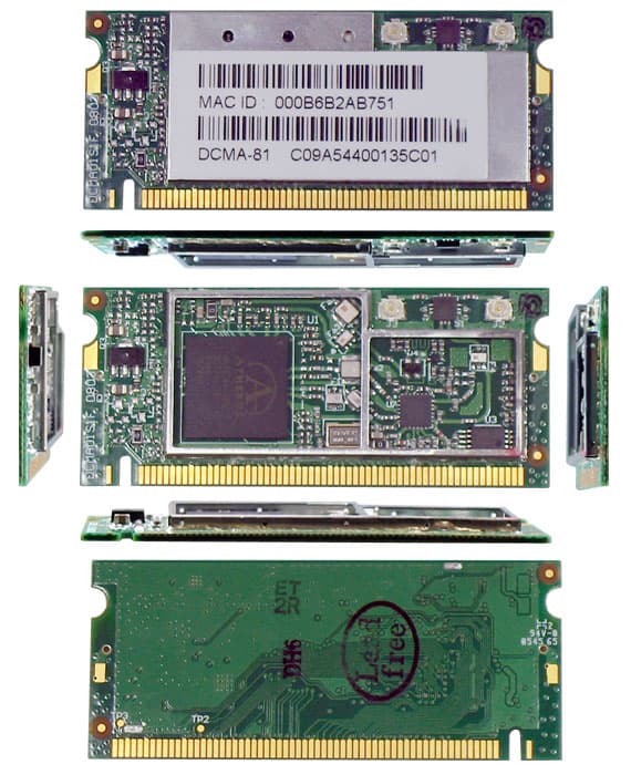
PQRDS540-MPCI6
Mar 28, 2006Wireless LAN MiniPCI Card
Equipment Class
NII - Unlicensed National Information Infrastructure TX
PQRDS540-MPCI4W
Dec 14, 2004Wireless LAN MiniPCI Card User Unit
Equipment Class
NII - Unlicensed National Information Infrastructure TX