PS6BR1000-A1PacketWave 1000 Series MMDS Base Station
Aperto Networks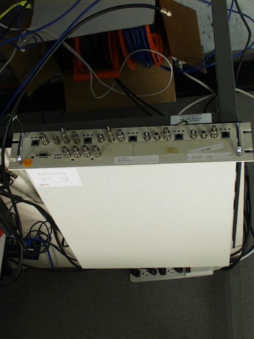
Click to zoom
Application Details
- Equipment Class
- TNB - Licensed Non-Broadcast Station Transmitter
- Date of Grant
- Dec 25, 2001
- Application Purpose
- Original Equipment
- Date of Application
- Dec 25, 2001
- Equipment Note
- PacketWave 1000 Series MMDS Base Station
- Frequency Range
- 2503.00000000 - 2683.00000000
- Company
- Aperto Networks
- Country
- United States
Documents & Files
Document Text
Text extracted from the exhibit documents filed with the FCC. Open a document above to read the original.
Users Manual
PACKETWAVE Fixed Broadband Wireless Access System PACKETWAVE 1000 SERIES BASE STATION EQUIPMENT Installation, Configuration, and Operation Manual 070-20000340-01 Rev. A, August, 2001 PacketWave 1000 Manual ©Copyright 2001 by Aperto Networks All rights reserved. Specifications subject to change. Aperto, PacketWave, WaveCenter, RapidBurst, OptimaLink, and ServiceQ are trademarks of Aperto Networks. All other trademarks used herein are the property of their respective owners. Aperto Networks 1637 South Main Street Milpitas, CA 95035 USA Phone: 408.719.9977 Fax: 408.719.9970 www.apertonet.com iii070-20000330-01 REGULATORY INFORMATION PART 15 This device complies with Part 15 of the FCC Rules. Operation is subject to the following two con- ditions: 1)this device may not cause harmful electromagnetic interference, and 2)this device must accept any interference received including interference that may cause undes- ired operations. FCC NOTICE: Radio and Television Interference The PacketWave 100 Series Subscriber Equipment has been tested and found to comply with the lim- its for a Class B digital device, pursuant to Part 15 of the FCC Rules. These limits are designed to provide reasonable protection against harmful interference in a residential installation. This equipment generates, uses, and can radiate radio frequency energy and, if not installed and used according to the instructions, may cause harmful interference to radio communications. However, there is no guarantee that interference will not occur in a particular installation. If this equipment does cause harmful inter- ference to radio or television reception, which is found by turning the equipment off and on, the user is encouraged to try to correct the interference by one or more of the following measures: •Reorient or relocate the receiving antenna. •Increase the separation between the equipment or device. •Connect the equipment to an outlet other than the receiver's. •Consult a dealer or an experienced radio/TV technician for assistance. RF Exposure Notice The installer shall mount all transmit antennas so as to comply with the limits for human exposure to radio frequency (RF) fields per paragraph 1.1307 of FCC regulations. The FCC requirements incor- porate limits for Maximum Permissible Exposure (MPE) in terms of electric field strength, magnetic field strength, and power density. CAUTION (5.8 GHz UNII) To comply with FCC RF exposure requirements, antennas used for this device must be installed to provide a separation distance of at least 1.5m from all persons. CAUTION (2.5 GHz MMDS) To comply with FCC RF exposure requirements in section 1.1307, a minimum separation distance of 20 cm. is required between this antenna and all persons. v070-20000340-01 Rev A TABLE OF CONTENTS Table of Contents PREFACE Scope of This Manual . . . . . . . . . . . . . . . . . . . . . . . . . . . . . . . . . . . . . . . . . . . . . . . . . . . .ix Conventions Used in This Manual . . . . . . . . . . . . . . . . . . . . . . . . . . . . . . . . . . . . . . . . . .x Intended Audience for this Manual . . . . . . . . . . . . . . . . . . . . . . . . . . . . . . . . . . . . . . . . . .x General Cautions and Warnings . . . . . . . . . . . . . . . . . . . . . . . . . . . . . . . . . . . . . . . . . . . .xi CHAPTER 1. QUICKSTART GUIDE Planning, Site Preparation, and Configuration . . . . . . . . . . . . . . . . . . . . . . . . . . . . . . . . .1-2 Installing and Starting Base Station Equipment . . . . . . . . . . . . . . . . . . . . . . . . . . . . . . . .1-5 Installing and Starting Subscriber Equipment . . . . . . . . . . . . . . . . . . . . . . . . . . . . . . . . . .1-6 CHAPTER 2. PACKETWAVE SYSTEM OVERVIEW Conceptual Overview of the PacketWave System . . . . . . . . . . . . . . . . . . . . . . . . . . . . . .2-1 Cell Size, Capacity, and Scalability . . . . . . . . . . . . . . . . . . . . . . . . . . . . . . . . . . .2-3 Multiple Frequency Bands . . . . . . . . . . . . . . . . . . . . . . . . . . . . . . . . . . . . . . . . . .2-3 IP-Based System . . . . . . . . . . . . . . . . . . . . . . . . . . . . . . . . . . . . . . . . . . . . . . . . .2-4 Range of Backhaul Options . . . . . . . . . . . . . . . . . . . . . . . . . . . . . . . . . . . . . . . . .2-4 Subscriber and Network Management . . . . . . . . . . . . . . . . . . . . . . . . . . . . . . . . .2-4 Technological Innovations . . . . . . . . . . . . . . . . . . . . . . . . . . . . . . . . . . . . . . . . . .2-5 RapidBurst . . . . . . . . . . . . . . . . . . . . . . . . . . . . . . . . . . . . . . . . . . . . . . .2-5 OptimaLink . . . . . . . . . . . . . . . . . . . . . . . . . . . . . . . . . . . . . . . . . . . . . . .2-5 ServiceQ . . . . . . . . . . . . . . . . . . . . . . . . . . . . . . . . . . . . . . . . . . . . . . . . .2-5 Base Station (Cell Site) Equipment . . . . . . . . . . . . . . . . . . . . . . . . . . . . . . . . . . . . . . . . . .2-6 Base Station Unit . . . . . . . . . . . . . . . . . . . . . . . . . . . . . . . . . . . . . . . . . . . . . . . . .2-6 Multiple Base Station Units . . . . . . . . . . . . . . . . . . . . . . . . . . . . . . . . . . .2-7 Base Station Radios and Antennas . . . . . . . . . . . . . . . . . . . . . . . . . . . . . . . . . . .2-7 Subscriber Site Equipment . . . . . . . . . . . . . . . . . . . . . . . . . . . . . . . . . . . . . . . . . . . . . . . .2-8 The PacketWave System’s IP Network . . . . . . . . . . . . . . . . . . . . . . . . . . . . . . . . . . . . . .2-10 Address Assignment . . . . . . . . . . . . . . . . . . . . . . . . . . . . . . . . . . . . . . . .2-13 Clustering Wireless Interfaces . . . . . . . . . . . . . . . . . . . . . . . . . . . . . . . .2-13 SU-to-SU Bridging . . . . . . . . . . . . . . . . . . . . . . . . . . . . . . . . . . . . . . . . . .2-13 Multiple Subnets on a Wireless Subsystem (WSS) . . . . . . . . . . . . . . . .2-14 Variable-Length Subnets (VLSM) . . . . . . . . . . . . . . . . . . . . . . . . . . . . . .2-15 Servers . . . . . . . …
Text truncated - open the document above for the full version.
Users Manual
6–11070-20000340-01 Rev A CHAPTER 6. BSU AND SUBSCRIBER CONFIGURATION Frame Parameters Click on the Frame tab so that the screen illustrated in Figure6-3 is displayed. Specify frame parameters as indicated in Table6-C. Table6-CBSU — WSS — Frame Parameters ParameterRange (and Default) Comments Edit WSS Filefile name (no default)If desired, click on the File Open icon at the right of the field and then select a file to use as a template for the WSS to be configured. TDD Frame Size2000 to 25000 ticks (5000) Advanced configuration parameter; change only if directed by Aperto Networks. Number of REQ Slots4 to 256 slots (4) Advanced configuration parameter; change only if directed by Aperto Networks. Upstream Portion Size1000 to 10000 ticks (1460) Adjust these parameters to alter the ratio of upstream to downstream bandwidth. Reduce the value of one by the amount you add to the amount of the other so the total remains the same (up + down = frame size - guardband). Downstream Portion Size1000 to 15000 ticks (3460) SYNC Interval10 to 500 ms (100) Advanced configuration parameter; change only if directed by Aperto Networks. CD Interval500 to 10000 ms (1000) Advanced configuration parameter; change only if directed by Aperto Networks. Downstream Max Link Mgmt Msg 1 to 255 (1) Advanced configuration parameter; change only if directed by Aperto Networks. Upstream Max Link Mgmt Msg 1 to 255 (1) Advanced configuration parameter; change only if directed by Aperto Networks. Initial Maintenance Interval5 to 5000 ms (500) Advanced configuration parameter; change only if directed by Aperto Networks. Periodic Maintenance Interval 10 to 60 seconds (30) Advanced configuration parameter; change only if directed by Aperto Networks. CPE Registration Timeout1 to 100 minutes (15) Advanced configuration parameter; change only if directed by Aperto Networks. CHAPTER 6. BSU AND SUBSCRIBER CONFIGURATION 6–12070-20000340-01 Rev A Channel Parameters Click on the Channel tab so that the screen illustrated in Figure6-4 is displayed. Specify channel parameters as indicated in Table6-D. Figure6-4WSS — Channel Menu 6–13070-20000340-01 Rev A CHAPTER 6. BSU AND SUBSCRIBER CONFIGURATION Table6-DBSU — WSS — Channel Parameters ParameterRange (and Default) Comments Channel Center Freq (MHz)9 menu options for frequency range, plus center frequency field Select the frequency range from the drop-down menu; then enter the channel center frequency to be used in communication with all subscribers in the sector. Required field. Symbol Rate Ratiorange x to y : a to b (1 : 1) Advanced configuration parameter; change only if directed by Aperto Networks. Not supported in R1P1. Sector name(no default)Enter the name chosen for the sector served by this WSS. Sector Number1 to 6 (1) Choose a number to identify the sector. Generally, you should use the WSS port number. Channel Width1000 to 7000 kHz (6000) Not supported in R1P1. Channel ID0 to 15 (1) Specify a channel identification number. Symbol Rate Allowed1 or 2 (1) Advanced configuration parameter; change only if directed by Aperto Networks. Not supported in R1P1. Flow ID Bits in SID1 to 6 (2) Advanced configuration parameter; change only if directed by Aperto Networks. Not supported in R1P1. CPE ID Bits in SID2 to 10 (10) Advanced configuration parameter; change only if directed by Aperto Networks. Not supported in R1P1. Ranging Tx Power Steps2 to 16 dBm, (4) Specify the step size for transmit power ranging. Antenna Gain0 to 48 dBi(15)Not supported in R1P1. CIR Bandwidth Allocation0 to 100% (0) Specify the percentage of the total bandwidth to be devoted to each of the three service classes. The three percentages should total exactly 100%. They should also correlate to the total bandwidths assigned to all subscribers in the sector, with appro- priate oversubscription based on statistical multi- plexing expectations. CBR Bandwidth Allocation0 to 100% (0) Best Effort Bandwidth Allocation 1 to 100% (100) CHAPTER 6. BSU AND SUBSCRIBER CONFIGURATION 6–14070-20000340-01 Rev A Radio Parameters Click on the Radio tab so that the screen illustrated in Figure6-5 is displayed. Specify radio parameters as indicated in Table6-E. Multiple Subnet Parameters Click on the Multiple Subnet tab so that the screen illustrated in Figure6-6 is displayed. Specify the WSS IP address and subnet mask for the first (and typically only) subnet, as indicated in Table6-F. Click on the save icon when you are finished. You must specify at least one subnet and mask before generating the WSS config- uration file. If desired, create another subnet by clicking on the new instance icon. Specify the WSS IP address and subnet mask for the new subnet. Click on the save icon when you are finished. Repeat for as many subnets as desired. CD Packet Parameters CD Packet parameters are not supported in R1P1. Preamble Parameters A configurable preamble is not supported in R1P1. 6–15070-20000340-01 Rev A CHAPTER 6. BSU AND SUBSCRIBER CONFIGURATION Figure6-5WSS — Radio Menu Table6-EBSU — WSS — Radio Parameters ParameterRange (and Default) Comments Min Tx Power-20 to 4 dBm (-12) Specify the minimum transmit power allowed in power ranging. Not supported in R1P1. Broadcast Tx Power-20 to 4 dBm (20) Specify the transmit power used for broadcasts to all subscribers. Not supported in R1P1. Max Tx Power-20 to 4 dBm (20) Specify the maximum transmit power allowed in power ranging. Not supported in R1P1. Number of Antennas1 or 2 (1) Specify whether this sector uses 1 or 2 antennas. Not supported in R1P1. Broadcast AntennaAntenna 1 or 2 (1) If this sector uses 2 antennas, specify the antenna to be used for broadcasts to all subscribers. Not supported in R1P1. Broadcast PolarizationHorizontal, Vertical, Horizontal & Vertical (Vertical) Specify the antenna polarization used for broad- casts to all subscribers. CHAPTER 6. BSU AND SUBSCRIBER CONFIGURATION 6–16070-20000340-01 Rev A Figure6-6WSS — Multiple Subnets Menu Table6-FBSU — WSS — Multiple Subnet Pa…
Text truncated - open the document above for the full version.
Cover Letter(s)
tel: 650-726-1263 fax: 650-726-1252 [email protected] Thomas N. Cokenias EMC &Radio Approvals Test & Consulting Services for Commercial, Military, International Compliance P.O. Box 1086 El Granada, CA 94018email: [email protected] 14 November 2001 FCC Laboratory 7435 Oakland Mills Road Columbia, MD 21046 Attention: Application Examiner Reviewing Engineer Re: Request for confidentiality per Section 0.459 of FCC Rules Applicant: Aperto Networks Equipment: MMDS Customer Premises Transceiver (Response Station) FCC ID: PS6BR1000-A1 To whom it may concern, Request is hereby submitted, on behalf of my client Aperto Networks., to withhold from public review certain portions of the application for equipment certification for the referenced FCC identifier. In particular, the following sections of the application and report are requested to be kept confidential: Schematics Block diagrams Parts list Theory of operation Rationale for request for confidentiality: Aperto has invested considerable time and materials in research and development to produce the referenced product. Disclosure of the confidential portions of this application to competitors would give them competitive advantage in developing similar products. If you have questions or need further information, please contact the undersigned. Sincerely, tel: 650-726-1263 fax: 650-726-1252 [email protected] THOMAS N. COKENIAS EMC Consultant/Agent for Aperto Networks
External Photos
Aperto Networks FCC ID: PS6BR1000-A1 Photographs, Base Station Indoor Unit
ID Label/Location Info
Aperto FCC ID: PS6SR1000-A1 label and location (rear surface) This device complies with Part 15 of theFCC rules. Operation is subject to the following two conditions: (1) This device may not cause harmful interference, and (2) this device must accept any interference that may cause undesired operation. FCC ID: PS6BR1000-A1 This device complies with Part 15 of theFCC rules. Operation is subject to the following two conditions: (1) This device may not cause harmful interference, and (2) this device must accept any interference that may cause undesired operation. FCC ID: PS6R3000-A1
RF Exposure Info
Aperto Networks 2.5 GHz MMDS CPE Unit FCC ID: PS6SR1000-A1 RF Hazard Distance Calculation mW/cm2 from Table1:1.00 Max RF Power TX AntennaMPE P, dBmG, dBiSafe Distance, cm 17.016.012.6 Basis of Calculations: E^2/3770 = S, mW/cm2 E, V/m = (Pwatts*Ggain*30)^.5/d, meters d = ((Pwatts*G*30)/3770*S))^0.5Pwatts*Ggain = 10^(PdBm-30+GdBi)/10) NOTE: For mobile or fixed location transmitters, minimum separation distance is 20 cm, even if calculations indicate MPE distance is less The CPE antenna is a flat panel array. Antenna gain is 16 dB. Manufacturer: Mti Wireless Edge Ltd. Model No. MT-30115 Antenna specification sheet is attached. Specification
Test Report
Aperto Networks FCC ID: PS6BR1000-A1 page 1 of 24 Product Description and Operation Overview General Overview The Aperto Networks MMDS band radio consists of a indoor unit (IDU) network interface and an outdoor unit (ODU) radio head. The IDU connects to the digital network via CAT5 cable. The IDU is connected to the ODU via shielded CAT5 cable for control and an RG6 with F connector for signal/data. (from user manual): The outdoor radio can be configured as either customer premises equipment (CPE) or as a base station unit (BSU). The radios are identical, except that the CPE uses an integral antenna, and the BSU has an antenna connector for separately mounted antennas. The base station IDU and subscriber IDU are different, but the output signals are the same and the radio heads used with them are the same except as outlined above. A description of the theory of operation and product configuration is found in an attachment to this application and report. SPECIFICATIONS ODU RF Head Frequency range: 2503 - 2683 MHz Channelization: 6 MHz channels, 1 MHz spacings Power output: 16 dBm Modulation type: QPSK, 16QAM IDU IF Head Frequency range: 44 MHz IF Aperto Networks FCC ID: PS6BR1000-A1 page 2 of 24 10 MHz reference clock Data transfer rate, air link: Up to 20 MBAs in a 6 MHz channel Block diagram and theory of operation is provided in a separate attachment. Aperto Networks FCC ID: PS6BR1000-A1 page 3 of 24 FCC CERTIFICATION INFORMATION The following information is in accordance with FCC Rules, 47CFR Part 2. 2.1033(c)1 Applicant: Aperto Networks 1635 S. Main Street Milpitas CA 95037 2.1033(c)2 FCC ID: PS6BR1000-A1 2.1033(c)3 Installation instructions are found in separate document. 2.1033(c)4 Emission type: QPSK and 16QAM Up to 20 MBPS Emission designator: 5M70G7W 2.1033(c)5 Frequency range: 2503 - 2683 MHz (6 MHz channel, 1 MHz spacings) 2.1033(c)6 Range of Operating Power 0 - 17 dBm 2.1033(c)7 Maximum Power Rating 17 dBm Maximum allowed per 21.909(g)2: 2 watts (33 dBm) 2.1033(c)8 Applied voltages and currents into the final transistor elements Refer to schematics, separate submission accompanying this application 2.1033(c)9 Tune-up procedure Refer to installation instructions in separate attachment. RF channel selection is achieved via control and set-up PC software via GUI. 2.1033(c)10 Circuit and Functional Block Diagram, Description of Circuitry Aperto Networks FCC ID: PS6BR1000-A1 page 4 of 24 Complete product schematics are provided in separate attachments. Circuit description and theory of operation are found in separate attachment. 2.1033(c)11 FCC ID Label Refer to separate attachment. 2.1033(c)12 Product Photographs Refer to separate attachment. Aperto Networks FCC ID: PS6BR1000-A1 page 5 of 24 2.1033(c)13 Description of Modulation System Refer to theory of operation, separate attachment 2.1033(c)14 Test Data per 2.1046 – 2.1057 (2) RF Output Power Measurements Measurement equipment used: Agilent E4440A Spectrum Analyzer Coaxial cable (worst case 1.9 dB attenuation at 26 GHz ) Test set-up: Figure 1 10/100 RG-6 (DC, IF, clock) baseT CAT 5 (alarm, radio control) PC PW1000 indoor unit (IDU) Outdoor radio unit (ODU) spectrum analyzer Test Procedures 1. Set the IDU channel bandwidth parameters and output level to desired values. Output level is chosen to maximize RF output level from ODU. 2. Connect cable between E4440A and ODU antenna output port. Activate Channel Power subroutine via E4440A soft keys, plot and record results. Test Results F(MHz) P requested P delivered 2503 17 dBm 17.08 dBm 2593 17 dBm 17.03 dBm 2683 17 dBm 17.05 dBm Aperto Networks FCC ID: PS6BR1000-A1 page 6 of 24 IDU output signal to ODU input port is shown below also. Aperto Networks FCC ID: PS6BR1000-A1 page 7 of 24 Power Output Spectrum Analyzer Graphs fo = 2503 MHz (low channel) Aperto Networks FCC ID: PS6BR1000-A1 page 8 of 24 Power Output Spectrum Analyzer Graphs fo = 2593 MHz (middle channel) Aperto Networks FCC ID: PS6BR1000-A1 page 9 of 24 Power Output Spectrum Analyzer Graphs fo = 2683 MHz (highest channel) Aperto Networks FCC ID: PS6BR1000-A1 page 10 of 24 IDU Output (10 MHz reference and 44 MHz IF) Aperto Networks FCC ID: PS6BR1000-A1 page 11 of 24 Section 2.1047 Modulation Characteristics Measurement equipment used: Agilent E4440A Spectrum Analyzer Coaxial cable (worst case 1.9 dB attenuation at 26 GHz ) Test set-up: Refer to Fig. 1. Test Procedures Software was run to produce a continuous pseudo random bit stream (prbs). Parameters were set to produce maximum IF output at the IDU. Test Results PASS. Refer to attached spectrum analyzer charts for three channels: Lowest: 2503 MHz Middle: 2593 MHz Highest: 2683 MHz Emissions masks at Lowest and Highest channels are shown with blue mask lines superimposed on spectrum analyzer charts. Aperto Networks FCC ID: PS6BR1000-A1 page 12 of 24 Channel Mask for fo = 2503 MHz (lowest channel) Aperto Networks FCC ID: PS6BR1000-A1 page 13 of 24 Channel mask for fo = 2683 MHz (highest channel) Aperto Networks FCC ID: PS6BR1000-A1 page 14 of 24 Section 2.1049 Occupied Bandwidth Measurement equipment used: Agilent E4440A Spectrum Analyzer Coaxial cable (worst case 1.9 dB attenuation at 26 GHz ) Test set-up: Fig. 2 laptop control PW1000 IDU RG-6 DC block Test Procedures and Results: Occupied bandwidth at ODU is identical to IF bandwidth at IDU. Using the built-in analyzer software routine, occupied BW is measured as 5.7 MHz. Refer spectrum analyzer plots below showing IDU occupied bandwidth. Aperto Networks FCC ID: PS6BR1000-A1 page 15 of 24 Occupied Bandwidth (at IF frequency) Aperto Networks FCC ID: PS6BR1000-A1 page 16 of 24 Section 2.1051 Spurious and Harmonic Emissions at Antenna Terminals Measurement equipment used: Agilent E4440A Spectrum Analyzer Coaxial cable (worst case 1.9 dB attenuation at 26 GHz ) Test set-up: Refer to Figure 1 above Test Procedures Section 21.908(e) requires that for a 100 kHz measurement bandwidth, all emissions removed from the channel edge …
Text truncated - open the document above for the full version.
Contact Information
Applicant
Leena Manwani(Sr Project Manager)
Technical Specifications
| # | Rule Parts | Frequency Range | Power Output | Emission | Tolerance |
|---|---|---|---|---|---|
| 1 | 21 | 2.50 GHz - 2.68 GHz | 50.00 mW | 5M70G7W | 0.0010000000 % |
Other Applications from Aperto Networks
PS6R3003-A1
Aug 29, 2004Packetwave Point-to-Point
Equipment Class
DTS - Digital Transmission System
PS6R3001-A1
Jan 23, 2003Wireless Utility Meter
Equipment Class
DTS - Digital Transmission System
PS6R3000-A2
Dec 12, 20025.8 GHz Wireless LAN
Equipment Class
DTS - Digital Transmission System
PS6SR1000-A1
Jan 08, 2002MMDS Customer Premises Equipment
Equipment Class
TNB - Licensed Non-Broadcast Station Transmitter
PS6R3000-A1
Aug 30, 2001WLAN Base Station and Subscriber Unit
Equipment Class
NII - Unlicensed National Information Infrastructure TX