PS6R3001-A1Wireless Utility Meter
Aperto Networks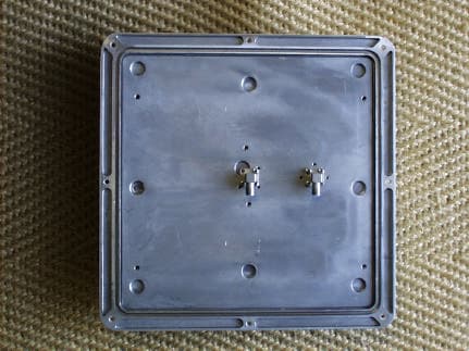
Click to zoom
Application Details
- Equipment Class
- DTS - Digital Transmission System
- Date of Grant
- Jan 23, 2003
- Application Purpose
- Original Equipment
- Date of Application
- Jan 23, 2003
- Equipment Note
- Wireless Utility Meter
- Frequency Range
- 5728.00000000 - 5847.00000000
- Company
- Aperto Networks
- Country
- United States
Documents & Files
Document Text
Text extracted from the exhibit documents filed with the FCC. Open a document above to read the original.
Users Manual
PacketWave 100 Series Subscriber Equipment Manual 070-20000750-01 Rev A, November 5, 2002 PacketWave TM Fixed Broadband Wireless System PacketWave 600 Series Installation, Configuration, and Operation Manual for Software Version 1.0 PacketWave 100 Installation and Operation ©Copyright 2002 by Aperto Networks All rights reserved. Specifications subject to change. Aperto, PacketWave, and WaveCenter are trademarks of Aperto Networks. All other trademarks used herein are the property of their respective owners. Aperto Networks 1637 South Main Street Milpitas, CA 95035 USA Phone: 408.719.9977 Fax: 408.719.9970 www.apertonet.com iii 070-20000340-01 Rev C1 REGULATORY INFORMATION FCC PART 15 This device complies with Part 15 of the FCC Rules. Operation is subject to the following two conditions: • this device may not cause harmful electromagnetic interference, and • this device must accept any interference received including interference that may cause undesired operations. FCC NOTICE: Radio and Television Interference The PacketWave TM 600 Series Base Station Equipment has been tested and found to com- ply with the limits for a Class A digital device, pursuant to Part 15 of the FCC Rules. These limits are designed to provide reasonable protection against harmful interference in a res- idential installation. This equipment generates, uses, and can radiate radio frequency energy and, if not installed and used according to the instructions, may cause harmful interference to radio communications. However, there is no guarantee that interference will not occur in a particular installation. If this equipment does cause harmful interfer- ence to radio or television reception, which is found by turning the equipment off and on, the user is encouraged to try to correct the interference by one or more of the following measures: • Reorient or relocate the receiving antenna. • Increase the separation between the equipment or device. • Connect the equipment to an outlet other than the receiver's. • Consult a dealer or an experienced radio/TV technician for assistance. iv 070-20000340-01 Rev C1 RF Exposure Notice The installer shall mount all transmit antennas so as to comply with the limits for human exposure to radio frequency (RF) fields per paragraph 1.1307 of FCC regulations. The FCC requirements incorporate limits for Maximum Permissible Exposure (MPE) in terms of electric field strength, magnetic field strength, and power density. CAUTION:5.8 GHz UNII — To comply with FCC RF exposure requirements, antennas used for this device must be installed to provide a separation distance of at least 2 m from all persons to satisfy RF exposure compliance. Canadian Standards Compliance This Class A digital apparatus complies with Canadian ICES-003 Cet appareil numérique de la classe A est conforme à la norme NMB-003 du Canada v 070-20000340-01 Rev C1 vi 070-20000340-01 Rev C1 xiii 070-20000750-01 Rev C1 Preface Scope of This Manual This manual documents the installation, configuration, and operation of the PacketWave 600 Series of Base Station and Subscriber Unit Equipment with software version 1.0. This manual provides the following information: • A conceptual overview of the PacketWave System. • Descriptions of the PacketWave hardware components, including base station and subscriber equipment. • Descriptions of the PacketWave software components, including configuration pro- grams and management interfaces. • Complete installation instructions • System configuration, management, and diagnostic procedures. Conventions Used in This Manual The term “Base Station Equipment” refers to the combination of the Base Station Indoor Unit, the radio, and the antenna. The term “Base Station Unit” refers to the Base Station Indoor Unit. PacketWave manuals represent special kinds of text as follows: • Files names and URLs are represented in italics, with variables described inside angle brackets. For example, if the URL http://<IP address>/ is referenced, you will replace the variable <IP address> with the appropriate real IP address. • Management interface text is represented by a bold font: for example, the Generate Config File button. Preface xiv 070-20000750-01 Rev C1 • Labels on equipment are represented in a bold font: for example, the Control con- nector. WARNING:This format is used to indicate the possibility of personal injury or seri- ous damage to equipment. CAUTION:This format is used to indicate the possibility of system or equipment operation problems. Items of special importance will be formatted and marked by a pointing-hand icon, as this paragraph is. Intended Audience for this Manual This manual is intended for system designers and planners, base station installers, system operators, and others requiring or desiring information about the PacketWave System. It provides information specific to the PacketWave system, but cannot and should not be considered a tutorial on relevant technologies and practices. It is expected that system designers and planners are knowledgeable about radio communications, cellular communication systems, and IP networks. Tutorials on these subjects are beyond the scope of this manual, and are readily available in published and online materials. Installation of radio equipment involves numerous factors, such as lightning and weather protection, requiring considerable expertise. It is assumed that equipment installers are professionals with knowledge of the principles and standard practices and procedures of cell site installation, all relevant safety requirements, and applicable local building codes. General Cautions and Warnings Observe the following when installing or operating any PacketWave System components. Carefully follow all local building and electrical codes, especially the latest revision of the National Electrical Code (NEC) and standard safety procedures for installing and working with this type of equipment. Improper procedures or installation can result in damage to th…
Text truncated - open the document above for the full version.
Users Manual
3–3 070-20000750-01 Rev A Chapter 3. Base Station Unit Web GUI Operation of the Web GUI The BSU and SU Web GUI pages share the basic elements identified in Figure 3-2. Main Menu and Submenu The Main Menu lists the various categories of functions available via the Web GUI. To select an item from the Main Menu, click on it. Orange crescents will bracket the menu item to show that it has been selected. The Submenu is context-sensitivity, changing as different Main Menu items are selected. The Submenu lists the pages available under the selected Main Menu category. Click on the appropriately-labeled box in the Submenu to display the desired page. Submitting and Uploading Changes Pages on which configuration changes can be entered include a Submit button at the bot- tom. Any change entered on the page does not take effect until the Submit button is clicked. Clicking Submit affects only the current operation of the BSU or SU. The corre- sponding configuration file located on the BSU’s permanent memory is not altered; there- fore, the configuration change will be lost if the BSU or SU is reset or re-powered. To update the BSU or SU permanent memory with changes made via the Web GUI, use the Upload Configuration button on the BSU or SU Device Control Utility page. Clicking the Upload Configuration button will cause all configuration changes currently in effect to be written into the permanent memory. Cancel and Refresh Buttons Some pages include Cancel and/or Refresh buttons at the bottom. These buttons have the following functions: •Clicking on the Cancel button cancels any changes made on the page; altered fields will return to their original contents. •Clicking on the Refresh button refreshes the window with the most up-to-date infor- mation. Hyperlinks Some Web GUI pages include hyperlinks to related pages. Hyperlinks are indicated in the method defined in your browser configuration. In some cases, hyperlinks are imple- mented using buttons similar to the Submit button. Chapter 3. Base Station Unit Web GUI 3–4 070-20000750-01 Rev A The Web GUI Home Page When you log on using the BSU’s IP address, you will be at the Home Page of the Base Station Unit’s Web GUI as shown on Figure 3-3. The Web GUI will log off after 15 minutes of inactivity. Activity can be either user input or automatic status updates performed by the Web GUI (as in the connectivity views described below). To keep the Web GUI from logging off when you will not be using it for more than 15 minutes, go to a page on which status is automatically updated. BSU/SU Connectivity From the BSU Home Page, you can access graphical connectivity view of the BSU and SU connection. Hyperlinks allow you to navigate through the connectivity view. The connectivity view provides a quick way to identify the configured BSU/SU, and to check their status. The arrows pointing to the Subscriber Unit in Figure 3-3 indicate wire- less channel status: green if good or red the Subscriber Unit is down. Figure 3-2Basic Elements in BSU and SU Web GUI 3–5 070-20000750-01 Rev A Chapter 3. Base Station Unit Web GUI Figure 3-3BSU Home: BSU/SU Connectivity Overview of BSU Web GUI Functions Table 3-A summarizes the functions available for each of the Main Menu and Submenu selection. Table 3-ASummary of the BSU Web GUI Main MenuSubmenuFunctions ConfigurationSystemShows general BSU information and status. Read-only. AdministrationSpecifies contact, location, and cell name. PasswordAllows users to change password for access to Web GUI, SNMP, CLI, and FTP. SNMPConfigures SNMP management of BSU. Local TimeSets local time, daylight savings parameters. IP FilterPer Ethernet/WSS: List of all defined IP filters. Hyperlinks to contents of individual filters. Read-only. Wireless InterfacePer WSS: Configuration pages for Frame, Channel, Radio. Read-only. HTML UpgradeHTML UpgradeUploads new HTML pages for Web GUI. UtilityDevice ControlSeveral commands: Reset BSU; Turn WSS On/Off; Reset WSS; Configuration Upload; Search IP address by Cus- tomer Name. Chapter 3. Base Station Unit Web GUI 3–6 070-20000750-01 Rev A Configuration Pages The Web GUI lets you check, and in some cases alter, the configuration of the Base Station Unit. Numerous BSU configuration pages may be displayed, as indicated by the submenu at the left of the page. System Configuration As shown in Figure 3-4, the System Configuration page identifies: • Ethernet parameters •Server settings • Operating software and configuration files, and current boot status. StatusBSU System StatusBSU software and hardware information, plus operational status. Read-only. SU Link StatusPer WSS: Gives upstream or downstream link status for all SUs with status. Read-only. PerformanceBSU System Statistics One-hour, Transmit or Receive byte count graph. Read- only. Bandwidth AllocationShows Upstream and Downstream allocation. RF Signal QualityShows RF signal quality statistics. BSU Flow StatisticsGives performance statistics for all defined service flows. Hyperlinks to specific flow details. Read-only. SU StatisticsShows SU with transmit and receive byte counts. Hyper- links to Subscriber Unit Web GUI. Read-only. FaultEvent logsList of logged BSU events. Read-only. E-mailConfiguration of e-mail alert reporting. Table 3-ASummary of the BSU Web GUI Main MenuSubmenuFunctions 3–7 070-20000750-01 Rev A Chapter 3. Base Station Unit Web GUI Figure 3-4System Configuration Page (BSU in bridge mode) Administration As shown in Figure 3-5, the Administration Configuration page allows viewing and altering of text fields related to BSU and cell administration. These text fields can be used for what- ever information system administrators deem useful. Click on the Submit button to acti- vate any changes made on this page. Password The Password Configuration page, shown in Figure 3-6, allows you to change the pass- word that is used to access the BSU’s Web GUI, SNMP, CLI, and FTP. Enter the password exactly the same in the two fields (the password is c…
Text truncated - open the document above for the full version.
Cover Letter(s)
tel: 650-726-1263 fax: 650-726-1252 [email protected] Thomas N. Cokenias EMC &Radio Approvals Test & Consulting Services for Commercial, Military, International Compliance P.O. Box 1086 El Granada, CA 94018 email: [email protected] 20 Nov 2002 FCC Laboratory 7435 Oakland Mills Road Columbia, MD 21046 Attention: Application Examiner Reviewing Engineer Re: Request for confidentiality per Section 0.459 of FCC Rules Applicant: Aperto Networks . FCC ID: PS6R3001-A1 To whom it may concern, Request is hereby submitted, on behalf of my client, Aperto Networks, to withhold from public review certain portions of the application for equipment certification for the referenced FCC identifier. In particular, the following sections of the application and report are requested to be kept confidential: Schematics Block Diagram Theory of Operations Rationale for request for confidentiality: Aperto Networks has invested considerable time and materials in research and development to produce the referenced product. Disclosure of the confidential portions of this application to competitors would give them competitive advantage in developing similar products. If you have questions or need further information, please contact the undersigned. Sincerely, tel: 650-726-1263 fax: 650-726-1252 [email protected] THOMAS N. COKENIAS EMC Consultant/Agent for Aperto Networks.
Cover Letter(s)
tel: 650-726-1263 fax: 650-726-1252 [email protected] Thomas N. Cokenias EMC &Radio Approvals Test & Consulting Services for Commercial, Military, International Compliance P.O. Box 1086 El Granada, CA 94018 email: [email protected] 20 Nov 2002 Compliance Certification Services 561 F Monterey Road Morgan Hill, CA 95037 Re: Certification Application for DTS Radio System Applicant: Aperto Networks FCC ID: PS6R3001-A1 The Aperto Networks DTS radio system consists of a base station and a subscriber unit, or Customer premise equipment (CPE). BASE STATION The base station consists of an indoor unit, the BSU (base station unit) which is connected between the 10/100 base T network and the radio unit, called the outdoor unit (ODU). The BSU provides DC power , 10 MHz reference signal, and a modulated 6 MHz wide 44 MHz IF signal to the ODU via a coaxial cable with an "F" style connector. The BSU also provides digital control and alarm signals to the ODU via a CAT5 cable, connected at both BSU and ODU ends by RJ45 connector. CUSTOMER PREMISE EQUIPMENT The CPE consists of an indoor unit (IDU) and an ODU. The IDU is connected between the 10/100 base T network and the ODU. The IDU provides DC power, 10 MHz reference signal, and 44 MHz IF to the ODU, along with control and alarm signals, in the same way as does the BSU. The Base Station ODU and the CPE ODU are identical, except that the CPE has an integrated antenna, and the Base Station ODU has a connector for an external antenna. tel: 650-726-1263 fax: 650-726-1252 [email protected]
External Photos
Apeto FCC ID: PS6R3001-A1 Product Photographs FCC ID: PS6R3001-A1 Product Photographs Bottom ODU Apeto FCC ID: PS6R3001-A1 Product Photographs ODU with integral antenna Apeto FCC ID: PS6R3001-A1 Product Photographs ODU used with external antennas (diversity receiver) Apeto FCC ID: PS6R3001-A1 Product Photographs Signal and control cable inputs
ID Label/Location Info
This device complies with Part 15 of theFCC rules. Operation is subject to the following two conditions: (1) This device may not cause harmful interference, and (2) this device must accept any interference that may cause undesired operation. FCC ID: PS6R3001-A1
Internal Photos
Apeto FCC ID: PS6R3001-A1 Product Photographs Cover removed Apeto FCC ID: PS6R3001-A1 Product Photographs Shield removed Apeto FCC ID: PS6R3001-A1 Product Photographs Foil side board Apeto FCC ID: PS6R3001-A1 Product Photographs Other side of shield Apeto FCC ID: PS6R3001-A1 Product Photographs Optional passive switch for connection to one of 6 antennas Apeto FCC ID: PS6R3001-A1 Product Photographs Optional passive switch for connection to one of 6 antennas Apeto FCC ID: PS6R3001-A1 Product Photographs Detail 6 antenna switch, component side of board Apeto FCC ID: PS6R3001-A1 Product Photographs Detail 6 antenna switch, foil side of board
RF Exposure Info
MPE Estimate FCC ID:PS6R3001-A1 Select the proper band and input the desired f to the corresponding cell next to it Input desire f in this column [one cell only] Controlled Envi Ave 6 min Uncontrolled Envi Ave 30 min Freq Band (MHz) Actual f [MHz] mW/cm2 mW/cm2 1500-100000 5800 5.0 1.0 Basis of Calculations: E^2/3770 = S, mW/cm2 Pwatts*Ggain = 10^(PdBm-30+GdBi)/10) E, V/m = (Pwatts*Ggain*30)^.5/d, meters d = ((Pwatts*G*30)/3770*S))^0.5 Max RF Power TX Antenna Gain MPE Antenna Type Power [dBm] Gain [dBi] Safe Distance [cm] 27.0 28.0 158.6 Dish Antenna 27.0 23.5 94.5 Panel Antenna 27.0 17.0 44.7 Integral Anenna 27.0 16.0 39.8 Panel/Sector 90 deg. 27.0 14.0 31.7 Sector 120 deg.
Test Report
FCC ID: PS6R3001-A1 1 EMISSIONS TEST REPORT FOR A LOW POWER TRANSMITTER I. GENERAL INFORMATION Requirement: Federal Communications Commissions Test Requirements: 15.205, 15.207, 15.209, 15.247 Applicant: Aperto Networks 1637 S Main Street Milpitas CA 95035 Product ID: FCC ID: PS6R3001-A1 II. DESCRIPTION OF EQUIPMENT UNDER TEST (EUT) The Aperto FCC ID: PS6R3001-A1 is a DTS radio system. RF Specifications RF Frequency Band 5728 - 5847 MHz RF Channels Programmable in 1 MHz steps Power programmable in 0.2 dB steps RF Signal Bandwidth 5.8 MHz (20 dB BW) Modulation Type 16 QAM or QPSK (dynamically selected) Transmitter Output Power +27 dBm maximum Antennas See table page 3 below III. TEST LOCATION All emissions tests were performed at: Compliance Certification Services 571F Monterey Road Morgan Hill, CA 95037 T.N. Cokenias 20 November 2002 FCC ID: PS6R3001-A1 2 EMC Consultant/Agent for Aperto Networks Inc. FCC ID: PS6R3001-A1 3 TEST PROCEDURES Measurement Equipment Used: HP 8564E 9Khz-40 Ghz Cal due 7-22-03 Radiated Emissions Above 1 GHz Test Requirement: 15.109, 15.205, 15.209, 15.247 Test Set-Up external mixer leveling pre-amp -OR- pre-amp HPF HP 8566 (26.5 - 40 GHz) (1-26.5 GHz) .3 m FCC ID: PS6R3001-A1 4 .3 - 1m horn antenna Test Procedures, 1- 26 GHz: 1. The EUT was placed on a wooden table resting on a turntable on the open air test site. The search antenna was placed 3m from the EUT. The EUT antenna was mounted vertically as per normal installation. 2. The turntable was slowly rotated to locate the direction of maximum emission at each emission falling in the restricted bands of 15.205. 3. Radiated emissions were investigated for a LOW channel, a MID channel, and HIGH channel. Emissions were investigated to the 10 th harmonic. 4. Once maximum direction was determined, the search antenna was raised and lowered in both vertical and horizontal polarizations. The maximum readings so obtained are recorded in the data listed below. Test Procedures, 26.5 - 40 GHz 1. The EUT was placed on a non-conductive table 2. The external mixer horn antenna was brought to within 1 foot (0.3m) of the EUT. 3. The horn antenna was moved around all surfaces of the EUT and EUT antenna in search of emissions coming from the EUT. This was done in both vertical and horizontal polarities Testing was performed at 3 different frequencies Channel Frequency, MHz Low 5728 Mid 5788 High 5847 Radiated emissions were performed at each frequency for 6 different transmitter antennas. Antennas tested: HP 8564 FCC ID: PS6R3001-A1 5 Antenna Type Deployment Gain Antenna Mfr. Model Integral antenna Point to Point 17 dBi European Antennas FPA19-55VH- APO2/821 Dish antenna Point to Point 28 dBi Radiowaves SP2-52 Panel antenna Point to Point 23.5 dBi Mobilemark FP-24-5800 Panel Point to Point Point to Multipoint 16 dBi MTi MT-484006 120 deg. Sector Point to Multipoint 14 dBi Radiowaves SEC-55-D-120-14 90 deg. Sector Point to Mulitpoint 16 dBi Radiowaves SEC-55-D-90-16 Test Results: Worst case results are presented. Refer to separate Excel spread sheet files. Radiated harmonic and spurious emissions levels were almost identical from antenna to antenna. Detected emissions appeared to emanate from case and not from antennas. Radiated Test Set-up, 30 - 1000 MHz Antenna mast Ground plane 1 - 4 meters 3 meters IDU AC turntable, laptop computer preamplifier spectrum analyzer Test Procedures, 30 -1000 MHz Test procedures were performed per ANSI C63.4 for ITE equipment. FCC ID: PS6R3001-A1 6 Emissions in 30 - 1000 MHz range were from radio local oscillators and digital circuitry of IDU ethernet section (15.109). Refer to data sheet below. FCC ID: PS6R3001-A1 7 FCC ID: PS6R3001-A1 8 AC Line Conducted Emissions Test Requirement: 15.107, 15.207 Measurement Equipment Used: Rohde & Schwarz EMI Receiver ESHS-20 Fischer Custom Communication LISN, FCC-LISN-50/250-25-2 Test Procedure 1. The EUT was placed on a wooden table 40 cm from a vertical ground plane and approximately 80 cm above the horizontal ground plane on the floor. The EUT was set to transmit in normally. 2. Line conducted data was recorded for both NEUTRAL and HOT lines. Test Results PASS. Refer to data sheet below. FCC ID: PS6R3001-A1 9 FCC ID: PS6R3001-A1 10 Minimum 6 dB Bandwidth Test Requirement: 15.247(a)2 Measurement Equipment Used: Agilent E3440 Spectrum Analyzer 3ft length low loss coaxial cable Test Procedures The EUT was configured on a test bench. The EUT was set for continuous operation . Frequency was set to LOW channel. While the transmitter broadcast a steady stream of digital data, the analyzer MAX HOLD function was used to capture the envelope of the transmission occupied bandwidth. The test was repeated at MID channel and at HIGH channel. Test Results: Refer to attached spectrum analyzer charts. Data taken with RES BW of 100 kHz shows minimum 6 dB BW of about 5 MHz. Minimum requirement: 500 kHz Channel Frequency, MHz Low 5728 Mid 5788 High 5847 FCC ID: PS6R3001-A1 11 15.247(a)2: Minimum 6 dB Bandwidth LOWChannel FCC ID: PS6R3001-A1 12 15.247(a)2: Minimum 6 dB Bandwidth MID Channel FCC ID: PS6R3001-A1 13 15.247(a)2: Minimum 6 dB Bandwidth HIGH Channel FCC ID: PS6R3001-A1 14 RF Power Output Test Requirement: 15.247(b) Measurement Equipment Used: Agilent E4416A power meter Agilent E9327A RF sensor 20 dB attenuator Test Procedures 1. The EUT was configured on a test bench. The power meter was zeroed and calibrated. The control software was activated and power was set to produce highest output level. 2. The 20 dB attenuator was connected to the antenna port of the EUT. The power meter head was connected to the other end of the attenuator. Peak power was read directly off the meter, accounting for the 20 dB attenuator. 3. The process in (1) and (2) was repeated for MID channel and HIGH channel. Test Results Power level readings converted to dBm are shown below. Refer also to spectrum analyzer graphs. Reference level offset corrects for external attenuation and cable loss. Ch…
Text truncated - open the document above for the full version.
Test Report
High FCC Measurement Compliance Certification Services, Morgan Hill Open Field Site 16.0feet Distance to Antenna 3.3feet Average Measurements:Peak Measurements: 1 MHz Resolution Bandwidth1MHz Resolution Bandwidth 10Hz Video Bandwidth1MHz Video Bandwidth f Peak R. Avg. R.AFCLAmpD CorrHPFPeakAvgPk Lim Avg LimPeak MarAvg MarNotes GHzdBuV dBuV dB/mdBdBdBdBdBuV/mdBuV/mdBuV/mdBuV/mdBdB 2.92240.132.629.84.4 -36.1-9.51.029.722.274.054.0-44.3-31.8 V NF 3.89645.633.032.45.3 -36.2-9.51.038.626.074.054.0-35.4-28.0 V NF 4.87046.234.032.76.1 -36.3-9.51.040.228.074.054.0-33.8-26.0 V NF 2.92240.532.629.84.4 -36.1-9.51.030.122.274.054.0-43.9-31.8 H NF 3.89640.532.632.45.3 -36.3-9.51.033.425.574.054.0-40.6-28.5 H NF 4.87036.033.032.76.1 -36.4-9.51.029.926.974.054.0-44.1-27.1 H NF 5.82036.833.032.56.9 -36.5-9.51.031.227.474.054.0-42.8-26.6 H NF Spurious Emission 20 dB below the Limit level Note: NF--Noise Floor levet fMeasurement FrequencyHPF Peak R. Analyzer Peak ReadingPeak Avg. R.Analyzer Avg.ReadingAvg AFAntenna Factor Pk Lim CLCable LossAvg Lim AmpPre amp gainPk Mar D CorrDiscorrections to 3 meterAvg Mar Cable length Customer Spurious Emi s11 Average Field Strength Limit Margin vs. Average Limit Margin vs. Peak Limit 11/20/02 Calculated peak field Strength Calculated average field Strength High Pass filter Peak Field Strength Limit Page 1
Test Report
mid FCC Measurement Compliance Certification Services, Morgan Hill Open Field Site EUT: Antenna No 2 16.0feet Distance to Antenna 3.3feet Average Measurements:Peak Measurements: 1 MHz Resolution Bandwidth1MHz Resolution Bandwidth 10Hz Video Bandwidth1MHz Video Bandwidth f Peak R. Avg. R.AFCLAmpD CorrHPFPeakAvgPk Lim Avg LimPeak MarAvg MarNotes GHzdBuV dBuV dB/mdBdBdBdBdBuV/mdBuV/mdBuV/mdBuV/mdBdB 5.78897.185.034.46.90.0-9.50.0128.9116.874.054.054.962.8 V 5.78879.666.034.46.90.0-9.50.0111.497.874.054.037.443.8 H 11.57746.935.039.29.9 -36.4-9.51.051.139.274.054.0-22.9-14.8 V 11.57741.433.032.59.9 -36.4-9.51.038.930.574.054.0-35.1-23.5 H NF 17.36442.029.345.313.4 -37.0-9.51.055.142.474.054.0-18.9-11.6 V NF 17.36441.029.032.513.4 -37.0-9.51.041.429.474.054.0-32.6-24.6 H NF 22.15063.843.832.55.0 -39.0 -20.01.043.323.374.054.0-30.7-30.7 V&H 26.00057.740.032.55.0 -37.0 -20.01.039.221.574.054.0-34.8-32.5 V&H NF fMeasurement FrequencyHPF Peak R. Analyzer Peak ReadingPeak Avg. R.Analyzer Avg.ReadingAvg AFAntenna Factor Pk Lim CLCable LossAvg Lim AmpPre amp gainPk Mar D CorrDiscorrections to 3 meterAvg Mar Cable length Customer 5788 Mh z Mid Channel: Average Field Strength Limit Margin vs. Average Limit Margin vs. Peak Limit 11/20/01 Calculated peak field Strength Calculated average field Strength High Pass filter Peak Field Strength Limit Page 1
Test Report
low FCC Measurement Compliance Certification Services, Morgan Hill Open Field Site Antenna No 3: SCC55D90-16 ( 16dBi ) 16.0feet Distance to Antenna 3.3feet Average Measurements:Peak Measurements: 1 MHz Resolution Bandwidth1MHz Resolution Bandwidth 10Hz Video Bandwidth1MHz Video Bandwidth f Peak R. Avg. R.AFCLAmpD CorrHPFPeakAvgPk Lim Avg LimPeak MarAvg MarNotes GHzdBuV dBuV dB/mdBdBdBdBdBuV/mdBuV/mdBuV/mdBuV/mdBdB 5.72894.883.934.46.80.0-9.50.0126.5115.674.054.052.561.6 V 5.72876.265.034.46.80.0-9.50.0107.996.774.054.033.942.7 H 11.45745.835.039.19.9 -39.6-9.51.046.735.974.054.0-27.3-18.1 V 11.45739.028.039.19.9 -39.6-9.51.039.928.974.054.0-34.1-25.1 H NF 17.18441.629.743.913.2 -44.1-9.51.046.234.374.054.0-27.8-19.7 V NF 17.18440.229.532.513.2 -44.1-9.51.033.422.774.054.0-40.6-31.3 H NF 18.00057.040.032.55.0 -39.0 -20.01.036.519.574.054.0-37.5-34.5 V&H NF 20.00057.040.032.55.0 -39.0 -20.01.036.519.574.054.0-37.5-34.5 V&H NF 26.00057.040.032.55.0 -39.0 -20.01.036.519.574.054.0-37.5-34.5 V&H NF Spurious emission 20dB below the limit level fMeasurement FrequencyHPF Peak R. Analyzer Peak ReadingPeak Avg. R.Analyzer Avg.ReadingAvg AFAntenna Factor Pk Lim CLCable LossAvg Lim AmpPre amp gainPk Mar D CorrDiscorrections to 3 meterAvg Mar Average Field Strength Limit Margin vs. Average Limit Margin vs. Peak Limit 11/20/02 Calculated peak field Strength Calculated average field Strength High Pass filter Peak Field Strength Limit Cable length Customer: TOM 5728MH z Low Channel: Page 1
Test Report
low FCC Measurement Compliance Certification Services, Morgan Hill Open Field Site Antenna No 4: Radiowave SEC-5V-120-14 16.0feet Distance to Antenna 3.3feet Average Measurements:Peak Measurements: 1 MHz Resolution Bandwidth1MHz Resolution Bandwidth 10Hz Video Bandwidth1MHz Video Bandwidth f Peak R. Avg. R.AFCLAmpD CorrHPFPeakAvgPk Lim Avg LimPeak MarAvg MarNotes GHzdBuV dBuV dB/mdBdBdBdBdBuV/mdBuV/mdBuV/mdBuV/mdBdB 5.72892.280.234.46.80.0-9.50.0123.9111.974.054.049.957.9 V 5.72875.564.534.46.80.0-9.50.0107.296.274.054.033.242.2 H 11.45741.029.039.19.9 -36.4-9.51.045.133.174.054.0-28.9-20.9 V NF 11.45738.028.039.19.9 -36.4-9.51.042.132.174.054.0-31.9-21.9 H NF 17.18442.030.043.913.2 -37.0-9.51.053.641.674.054.0-20.4-12.4 V NF 17.18440.029.032.513.2 -37.0-9.51.040.229.274.054.0-33.8-24.8 H NF 18.00057.040.032.55.0 -39.0 -20.01.036.519.574.054.0-37.5-34.5 V&H NF 22.00057.040.032.55.0 -39.0 -20.01.036.519.574.054.0-37.5-34.5 V&H NF 26.00057.040.032.55.0 -39.0 -20.01.036.519.574.054.0-37.5-34.5 V&H NF Spurious emission 20dB below the limit level fMeasurement FrequencyHPF Peak R. Analyzer Peak ReadingPeak Avg. R.Analyzer Avg.ReadingAvg AFAntenna Factor Pk Lim CLCable LossAvg Lim AmpPre amp gainPk Mar D CorrDiscorrections to 3 meterAvg Mar Average Field Strength Limit Margin vs. Average Limit Margin vs. Peak Limit 11/20/02 Calculated peak field Strength Calculated average field Strength High Pass filter Peak Field Strength Limit Cable length Customer: TOM 5728MH z Low Channel: Page 1
Test Report
low FCC Measurement Compliance Certification Services, Morgan Hill Open Field Site Antenna No 5: MT-484006 ( 16dBi ) 16.0feet Distance to Antenna 3.3feet Average Measurements:Peak Measurements: 1 MHz Resolution Bandwidth1MHz Resolution Bandwidth 10Hz Video Bandwidth1MHz Video Bandwidth f Peak R. Avg. R.AFCLAmpD CorrHPFPeakAvgPk Lim Avg LimPeak MarAvg MarNotes GHzdBuV dBuV dB/mdBdBdBdBdBuV/mdBuV/mdBuV/mdBuV/mdBdB 5.72893.782.734.46.80.0-9.50.0125.4114.474.054.051.460.4 V 5.72875.565.234.46.80.0-9.50.0107.296.974.054.033.242.9 H 11.45738.527.039.19.9 -36.4-9.51.042.631.174.054.0-31.4-22.9 V NF 11.45737.026.039.19.9 -36.4-9.51.041.130.174.054.0-32.9-23.9 H NF 17.18440.529.543.913.2 -37.0-9.51.052.141.174.054.0-21.9-12.9 V NF 17.18441.030.032.513.2 -37.0-9.51.041.230.274.054.0-32.8-23.8 H NF 20.00057.040.032.55.0 -39.0-9.51.047.030.074.054.0-27.0-24.0 H NF 22.00057.040.032.55.0 -39.0-9.51.047.030.074.054.0-27.0-24.0 H NF 26.00057.040.032.55.0 -39.0-9.51.047.030.074.054.0-27.0-24.0 H NF Spurious emission 20dB below the limit level fMeasurement FrequencyHPF Peak R. Analyzer Peak ReadingPeak Avg. R.Analyzer Avg.ReadingAvg AFAntenna Factor Pk Lim CLCable LossAvg Lim AmpPre amp gainPk Mar D CorrDiscorrections to 3 meterAvg Mar Average Field Strength Limit Margin vs. Average Limit Margin vs. Peak Limit 11/20/02 Calculated peak field Strength Calculated average field Strength High Pass filter Peak Field Strength Limit Cable length Customer…
Text truncated - open the document above for the full version.
Contact Information
Applicant
Leena Manwani(Sr Project Manager)
Test Firm
Compliance Certification Services IncSteve Cheng
Technical Specifications
| # | Rule Parts | Frequency Range | Power Output |
|---|---|---|---|
| 1 | 15C | 5.73 GHz - 5.85 GHz | 500.00 mW |
Other Applications from Aperto Networks
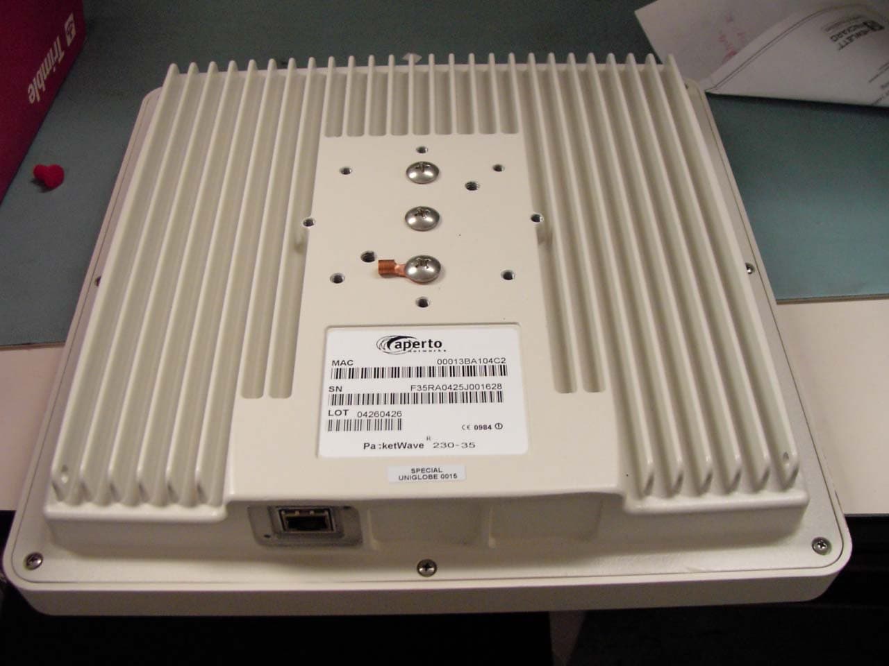
PS6R3003-A1
Aug 29, 2004Packetwave Point-to-Point
Equipment Class
DTS - Digital Transmission System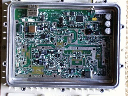
PS6R3000-A2
Dec 12, 20025.8 GHz Wireless LAN
Equipment Class
DTS - Digital Transmission System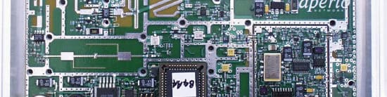
PS6SR1000-A1
Jan 08, 2002MMDS Customer Premises Equipment
Equipment Class
TNB - Licensed Non-Broadcast Station Transmitter
PS6BR1000-A1
Dec 25, 2001PacketWave 1000 Series MMDS Base Station
Equipment Class
TNB - Licensed Non-Broadcast Station Transmitter
PS6R3000-A1
Aug 30, 2001WLAN Base Station and Subscriber Unit
Equipment Class
NII - Unlicensed National Information Infrastructure TX