PURBSERIESGSMNA10B-Series GSM 1.0
RadioFrame Networks, Inc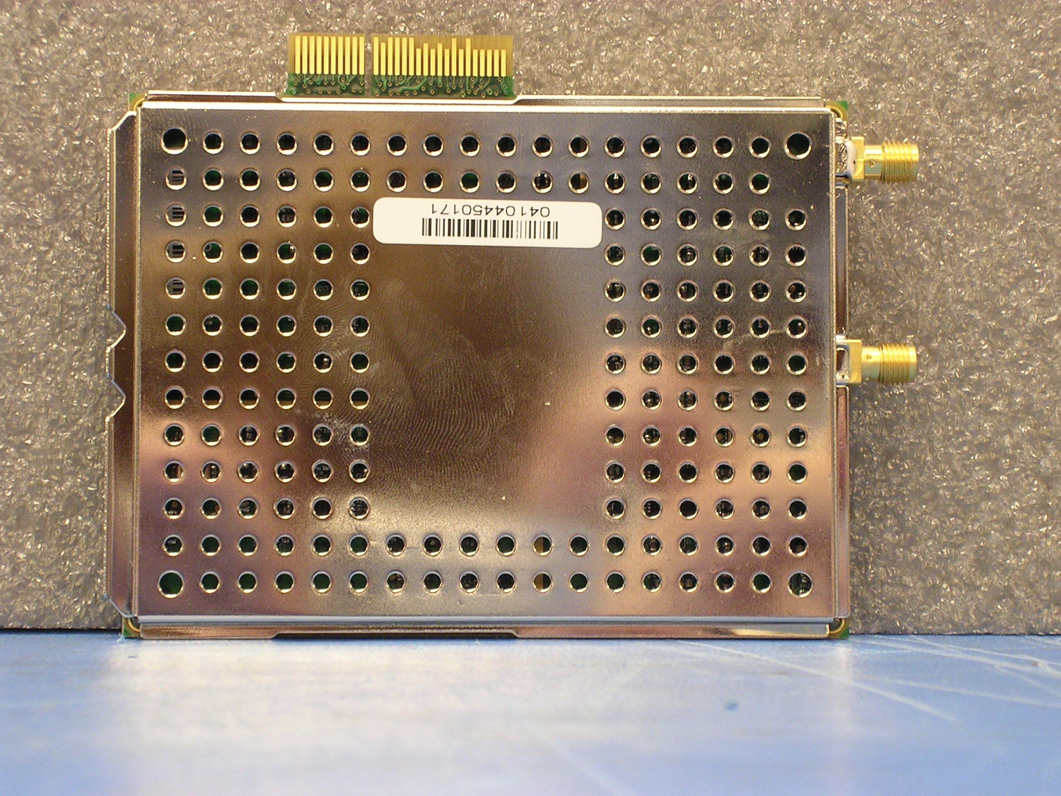
Click to zoom
Application Details
- Equipment Class
- PCB - PCS Licensed Transmitter
- Date of Grant
- May 03, 2005
- Application Purpose
- Original Equipment
- Date of Application
- May 03, 2005
- Equipment Note
- B-Series GSM 1.0
- Frequency Range
- 869.00000000 - 894.00000000
- Company
- RadioFrame Networks, Inc
- Country
- United States
Documents & Files
Document Text
Text extracted from the exhibit documents filed with the FCC. Open a document above to read the original.
Users Manual
RadioFrame Networks RadioFrame System Method of Procedure GSM/802.11b April 25, 2005 998-4002-00 Rev C RadioFrame System Method of Procedure GSM/802.11b ii RadioFrame Networks, Inc. Service Information This equipment complies with part 15 of the FCC Rules. Operation is subject to the two following conditions: This device may not cause harmful interference, and this device must accept any interference received, including interference that may cause undesired operation. This equipment has been tested and found to comply with the limits pursuant to part 90.691 of the FCC Rules. These limits are designed to provide reasonable protection against harmful interference when the equipment is operated in a commercial environment. Notices These installation standards have been prepared to provide RadioFrame Networks Customers with general standards necessary to ensure that installed RadioFrame Networks equipment operates in accordance with the design parameters in the owned or leased buildings of RadioFrame Networks Customers and their customers, and to make certain equipment is installed safely and efficiently. RadioFrame Networks reserves the right to revise this document for any reason, including, but not limited to, conformity with standards promulgated by various governmental or regulatory agencies, utilization of advances in the state of the technical arts, or to reflect changes in the design of equipment, techniques, or procedures described or referred to herein. Liability to anyone arising out of use or reliance upon any information set forth herein is expressly disclaimed, and no representation or warranties, expressed or implied, are made with respect to the accuracy or utility of any information set forth herein. Revision History Software Release Date Pre-release July 2004 To Obtain Copies Contact RadioFrame Networks at: • RadioFrame Networks, Inc. 1120 112 th Avenue NE, Suite 600 Bellevue, WA 98004 • Telephone (425) 278-2780 • FAX (425) 278-2781 • E-mail [email protected] Final copies of this document are also posted as .pdf files on the RadioFrame Networks web site at: http//www.radioframenetworks.com. Your Comments are Valued The information in this document is subject to change. Please do not hesitate to point out discrepancies, express your concerns and make suggestions. Copyrights and Trademarks RadioFrame is a registered trademark; RadioFrame Networks and RadioBlade are trademarks of RadioFrame Networks, Inc. You may not use these or any other RadioFrame Networks trademarks or service marks without the written permission of RadioFrame Networks, Inc. All other trademarks and trade names are the property of their respective owners. Throughout this publication, the terms RadioFrame Networks, RadioFrame and RFN signify RadioFrame Networks, Inc. RadioFrame System GSM/802.11b/g Method of Procedure © Copyright 2005 RadioFrame Networks, Inc. All Rights Reserved. GSM/802.11b RadioFrame System Method of Procedure RadioFrame Networks, Inc. iii Contents 1 Introduction ............................................................................................................... 1 1.1 Scope of the Manual........................................................................................ 1 1.2 Repair and Technical Support ......................................................................... 3 1.3 Safety Precautions .......................................................................................... 4 2 System Description................................................................................................... 8 2.1 Base Chassis Unit (BCU) ................................................................................ 9 2.2 Airlink Chassis Unit (ACU)............................................................................. 10 2.3 RadioFrame Unit (RFU)................................................................................. 10 2.4 GSM RadioBlade (RadioBlade or RB)........................................................... 11 2.5 802.11b/g integrated RadioFrame Access Point (RAP) ................................ 11 2.6 Local Area Network (LAN) ............................................................................. 12 2.7 Physical Relationships................................................................................... 13 3 Pre-Installation ........................................................................................................ 18 3.1 Receipt of Equipment .................................................................................... 18 3.2 Site Planning ................................................................................................. 19 3.3 Main Rack and Supporting Hardware............................................................ 20 3.4 Remote ACUs................................................................................................ 30 3.5 RFUs ............................................................................................................. 32 3.6 GSM RadioBlades ......................................................................................... 34 3.7 RAPs ............................................................................................................. 36 3.8 Interconnecting Cabling................................................................................. 37 3.9 Main Rack Configuration ............................................................................... 44 3.10 RF Planning................................................................................................... 45 3.11 Site Survey .................................................................................................... 45 3.12 Tools Required .............................................................................................. 45 4 Installation ............................................................................................................... 47 4.1 Ma…
Text truncated - open the document above for the full version.
Users Manual
981-0631-00 Rev 2 RadioFrame Networks™, Inc.; 1120 112 th Ave NE Suite 600 Bellevue, WA 98004 [email protected] or 425.424.7620 NA GSM Dual-Band RadioBlade FCC Compliance Certified to 47 CFR Part 90. Licensed operation required. Radio Frequency exposure approved for fixed installations only. Unit should be installed to provide at least 20 cm from all persons to satisfy Radio Frequency Radiation Exposure requirements of FCC 2.1091. Caution Changes or modifications not expressly approved by the party responsible for compliance could void the user's authority to operate the equipment. Specifications Operating Environment • Operating Ambient Temperature: +0 o C to +40 o C (+32 o F to +104 o F) • Storage Temperature: -40 o C to +70 o C (-40 o F to +158 o F) • Relative Humidity: 10-90% non condensing • Altitude: -200 to +8000 feet above mean sea level; above 8000', reduce maximum operating ambient temperature by 2 o C per 1000' to a maximum of 13000' • Shock: 40 g’s • Vibration: Level 3 earthquake • Keep product free from dust, wind, salt, liquids Agency Compliance FCC Part 90 UL/cUL 60950 IC-RSS 119 CE Mark ISTA 2A transit Physical Specifications • Dimensions: 3" wide x 4" high (plus antenna) x 0.5" thick (approx.) • Weight: 1 lb (approx.) Input Power • 3.3 VDC, 720mA max • 2.5 VDC, 50mA max Tx and Rx Power and Center Frequency Ranges • Tx power range: -30 to +10dBm +/-3dB • Tx power range low band (GSM 800): +12.2 to -13.8 • Tx power high band (PCS 1900): +15.7 to -10.3 • Low Band (GSM 800) center frequency range: Tx: 869 to 894 MHz Rx: 824 to 849 MHz • High Band (PCS1900) center frequency range: Tx: 1930 to 1990 MHz Rx: 1850 to 1910 MHz 981-0631-00 Rev 2 Installation Instructions and Guidelines 1. Find these items in the shipping box: NA GSM Dual Band RadioBlades in individually wrapped antistatic bags, and one disposable antistatic wrist strap. 2. Unwrap 30 cm (12”) of the disposable antistatic wrist strap and wrap the adhesive side around your wrist. 3. Unroll the rest of the band and remove the liner from the copper tape. 4. Attach the copper tape to the metal card cage inside the RadioFrame Unit (RFU). 5. Insert the NA GSM Dual Band RadioBlades into the specified slots in the RFU as shown in the diagram above. For safe operation: • Do not mount the unit in any orientation other than that specified in the diagram. • Do not force the RadioBlade, or damage to equipment can occur. • Slide the top of the RadioBlade into the metal slot on top of the RFU until the RadioBlade connector seats firmly into the backplane. 6. Remove the antistatic wrist strap and dispose of it, 7. Place the front cover on the RFU. Copyrights/Trademarks © Copyright 2003 RadioFrame Networks, Inc., USA. All rights reserved. RadioFrame Networks, RadioBlade, and the RadioFrame Networks logo are trademarks; RadioFrame is a registered trademark of RadioFrame Networks, Inc. USA.
Cover Letter(s)
Northwest EMC TCB Compliance Opinion Revision 05//02 RAFN0044 Information about the Applicant Applicant: Radioframe Networks, Inc. Address: 1120 112th Ave NE, Suite 600 City, State, Zip Bellevue, WA 98004 Test Requested By: Steve Peters Model: B-Series GSM 1.0 FCC ID: PURBSERIESGSMNA10 Agent Radioframe Networks, Inc. Approval Type Certification Equipment Type Base Station transceiver Rule Part 22H and 24E Overview GSM 850 This base station transceiver is designed for use in the GSM 800 MHz cellular telephone system. The transmitter will operate from 869.2 to 893.8 MHz. The receiver circuit supports 824.2 to 848.8 MHz. The base station operates in the 800 MHz broadband Cellular services as per 47 CFR Part 22 subpart H, 22.901 (d). It meets the requirements of GSM 1900 11.10-1 version 4.19.1 specification for operation in GSM cellular systems except for the output frequency range. This transceiver will in normal mode operate at a nominal output peak power of 16.44 mW per channel at the antenna connector. The power output is reducible to ~0.3 watts.. GSM 1900 This base station transceiver is designed for use in the GSM 1900 MHz cellular telephone system. The transmitter will operate from 1930.4 to 1989.6 MHz. The receiver circuit supports 1850.4 to 1809.6 MHz. The base station operates in the 1900 MHz broadband PCS services as per 47 CFR Part 24 subpart E. It meets the requirements of GSM 1900 11.10-1 version 4.19.1 specification for operation in GSM cellular systems. This base station will in normal mode operate at a nominal power out of 36.98 milliwatts at the antenna connector. The power output is reducible to ~0.3 watts. Northwest EMC TCB Compliance Opinion Revision 05//02 RAFN0044 Findings Finding 47 Cfr 2.1033(c)9) Tune-up procedure over the power range, or at specific operating power levels. Resolution Information has been provided. Finding 47 CFR 1.1310 Radiofrequency radiation exposure limits. The criteria listed in table 1 shall be used to evaluate the environmental impact of human exposure to radiofrequency (RF) radiation as specified in Sec. 1.1307(b), except in the case of portable devices, which shall be evaluated according to the provisions of Sec. 2.1093 of this chapter. Further information on evaluating compliance with these limits can be found in the FCC's OST/OET Bulletin Number 65, ``Evaluating Compliance with FCC- Specified Guidelines for Human Exposure to Radiofrequency Radiation.'' The RF Exposure Exhibit is not correct; PURIRAP10 has different output power characteristics listed in the different tables. Resolution New Exhibits have been provided Finding 47 CFR Sec. 15.19 Labeling requirements. (1) Receivers associated with the operation of a licensed radio service, e.g., FM broadcast under part 73 of this chapter, land mobile operation under part 90, etc., shall bear the following statement in a conspicuous location on the device: This device complies with part 15 of the FCC Rules. Operation is subject to the condition that this device does not cause harmful interference. Resolution Information has been provided. (GSM-802 Users Manual) Recommendation All items have been resolved and completed to my satisfaction; therefore I recommend this application for approval. Signature 4/27/2005 Dean Ghizzone, TCB Committee Northwest EMC TCB Compliance Opinion Revision 05//02 RAFN0044 Opinion Specification Requirements Description 15.107 Conducted Power Line Emissions Opinion: The Equipment meets the intent specified by the requirements listed above Discussion: The Applicant has submitted test results in the form of a test report. Reference: Technical Report Specification Requirements Description FCC 15.109 Radiated Emissions Opinion: The Equipment meets the intent specified by the requirements listed above. Discussion: The Applicant has submitted test results in the form of a test report Reference: Technical Report Specification Requirements Description 2.1055, 24.235 Frequency Stability Opinion: The Equipment meets the intent specified by the requirements listed above. Discussion: The Applicant has submitted test results in the form of a test report Reference: Technical Report Specification Requirements Description 2.1049, 22.917, 24.238 Occupied Bandwidth Opinion: The Equipment meets the intent specified by the requirements listed above. Discussion: The Applicant has submitted test results in the form of a test report Reference: Technical Report Specification Requirements Description 2.1046 Output Power Opinion: The Equipment meets the intent specified by the requirements listed above. Discussion: The Applicant has submitted test results in the form of a test report. Reference: Technical Report Northwest EMC TCB Compliance Opinion Revision 05//02 RAFN0044 Specification Requirements Description 22.917(e), 24.238(a) ERP Opinion: The Equipment meets the intent specified by the requirements listed above. Discussion: The Applicant has submitted test results in the form of a test report. Reference: Technical Report Specification Requirements Description 2.1051, 22.917, 24.238 Spurious Conducted Emissions - Transmit Opinion: The Equipment meets the intent specified by the requirements listed above. Discussion: The Applicant has submitted test results in the form of a test report Reference: Technical Report Specification Requirements Description 15.111(a) Spurious Conducted Emissions - Receive Opinion: The Equipment meets the intent specified by the requirements listed above. Discussion: The Applicant has submitted test results in the form of a test report. Reference: Technical Report Specification Requirements Description 22.917(e), 24.238(a) Spurious Radiated Emissions Opinion: The Equipment meets the intent specified by the requirements listed above. Discussion: The Applicant has submitted test results in the form of a test report. Reference: Technical Report Specification Requirements Description 22.917(e), 24.238(a) Spurious Radiated Emissions – Simultaneous Transmit Opinion: Th…
Text truncated - open the document above for the full version.
Parts List/Tune Up Info
NA_GSMv7_BOM_from_schematic.txt NA GSM RadioBlade Revised: Thursday, August 05, 2004 928-0631-07 Revision: A RadioFrame Networks, Inc. 1120 112th Avenue NE Suite 600 Bellevue, WA 98004 http://www.radioframenetworks.com Bill Of Materials December 15,2004 17:15:21 Page1 Item Quantity Reference Part RFN P/N ______________________________________________ 1 2 CR1,CR2 Super Red LED 830-0510-00 2 28 C1,C12,C22,C24,C51,C71, 4.7uF 392-475-9K C79,C80,C81,C108,C125, C130,C138,C142,C150,C162, C198,C205,C208,C235,C251, C252,C253,C284,C299,C301, C316,C317 3 56 C2,C11,C23,C30,C31,C34, 0.1uF 330-104-1Z C41,C42,C47,C48,C53,C66, C72,C77,C88,C95,C97,C107, C114,C121,C131,C163,C164, C165,C167,C170,C171,C175, C177,C185,C189,C190,C196, C216,C224,C227,C229,C232, C239,C241,C250,C254,C256, C285,C286,C288,C291,C292, C293,C297,C300,C303,C306, C310,C312,C313 4 48 C3,C4,C5,C6,C7,C9,C10, 68pF 300-680-3G C13,C15,C17,C18,C19,C21, C26,C27,C33,C39,C45,C46, C56,C57,C58,C59,C60,C63, C64,C70,C74,C119,C124, C128,C148,C237,C260,C262, C266,C276,C277,C278,C282, C283,C290,C294,C295,C307, C308,C315,C318 5 5 C8,C25,C220,C258,C296 560pF 310-561-1J 6 12 C14,C16,C20,C28,C35,C40, 22pF 300-220-3G C43,C55,C144,C147,C154, C302 7 1 C29 0.1uF 311-104-1M 8 28 C32,C36,C52,C54,C61,C83, 0.01uF 310-103-1K C84,C87,C92,C96,C120, C134,C135,C137,C140,C141, C145,C157,C179,C200,C202, C240,C243,C244,C245,C246, C271,C279 9 11 C37,C38,C44,C49,C50,C225, 120pF 300-121-3G C242,C248,C259,C287,C309 10 16 C62,C69,C73,C86,C90,C91, 100pf 300-101-3G C93,C99,C106,C109,C112, C116,C117,C118,C126,C136 11 18 C65,C168,C169,C172,C173, 270pF 310-271-1J C174,C178,C180,C181,C182, C187,C188,C193,C197,C218, C221,C226,C249 12 4 C67,C82,C115,C133 270pF 300-271-5J 13 10 C68,C89,C98,C143,C233, 470pF 300-471-5J Page 1 NA_GSMv7_BOM_from_schematic.txt C238,C265,C273,C275,C314 14 1 C75 2.2pF 300-2R2-5B 15 22 C76,C100,C102,C110,C149, 1000pF 310-102-1K C160,C176,C184,C186,C191, C194,C210,C222,C230,C255, C272,C274,C280,C281,C298, C304,C305 16 7 C78,C104,C113,C152,C158, 15pf 300-150-5G C159,C264 17 1 C85 39pf 300-390-5J 18 5 C94,C101,C123,C151,C269 1.8pF 300-1R8-5B 19 6 C103,C105,C146,C192,C219, 8.2pF 300-8R2-3B C323 20 42 JP1,R7,R18,L27,L37,L41, DNI Do Not Install R44,R45,R52,R56,R60,R77, R84,R91,R93,R94,R102, R103,R105,R109,C111,R121, C129,R134,R143,R177,C183, C201,C204,C206,C209,C212, C217,R283,R284,R293,R295, R296,R300,R301,C320,C321 21 1 C122 5.6pF 300-5R6-5C 22 4 C127,C153,C324,C325 2.7pF 300-2R7-3B 23 2 C166,C132 1uF 391-105-9K 24 5 C139,C236,C267,C289,C319 33pf 300-330-3G 25 1 C155 4.7pF 300-4R7-5B 26 2 C268,C156 1.0pF 300-1R0-5B 27 4 C161,C199,C261,C311 0.33uF 391-334-9K 28 1 C195 330pF 310-331-1J 29 3 C203,C211,C214 82pF 300-820-3G 30 1 C207 10pf 300-100-5C 31 2 C213,C215 4700pF 310-472-1K 32 2 C228,C223 18pf 300-180-5J 33 1 C231 1.0pF 300-1R0-5B 34 1 C234 1.2pF 300-1R2-5B 35 2 C247,C257 47pF 300-470-3G 36 2 C270,C263 0.8pF 300-0R8-3C 37 1 C322 DNI Do Not Install 38 1 C326 1.5pF 300-1R5-5B 39 1 FB1 4.0A Ferrite Bead 501-0531-00 40 2 FL1,FL2 881.5 & 1960 MHz 500-0200-00 41 25 FL3,FL4,FL5,FL7,FL8,FL9, 150 MHz 500-0150-00 FL11,FL12,FL13,FL14,FL15, FL16,FL25,FL26,FL27,FL28, FL29,FL30,FL31,FL32,FL33, FL34,FL35,FL36,FL37 42 3 FL6,FL10,FL17 4MHz LPF 500-0160-00 43 2 FL19,FL18 TFS246H4 500-0120-00 44 1 FL20 10.7 MHz 500-0109-00 45 2 FL21,FL23 1880 MHz 500-0220-00 46 1 FL22 836.5 MHz 500-0210-00 47 1 FL24 835.5 MHz 500-0210-00 48 2 J2,J1 SMA 802-0100-02 49 2 L17,L1 3.9nH 490-3R9-0J-1 50 27 L2,L3,L4,L5,L9,L11,L12, 27nH 490-270-0J L13,L14,L15,L16,L19,L20, L21,L22,L23,L24,L26,L32, L44,L68,L72,L77,L83,L86, L88,L89 51 4 L6,L10,L71,L84 2.0nH 490-2R0-0J-1 52 6 L7,L8,L18,L51,L74,L85 820nH 492-0821-0J 53 2 L73,L25 22nH 491-0220-0J 54 1 L28 15nH 490-150-0J-1 Page 2 NA_GSMv7_BOM_from_schematic.txt 55 1 L29 1.0nH 490-1R0-0J-1 56 3 L30,L38,L76 6.2nH 490-6R2-0J-1 57 4 L31,L34,L70,L87 2.2nH 490-2R2-0J-1 58 5 L33,L65,L75,L79,L81 10nH 490-100-0G 59 1 L35 4.7nH 490-4R7-0J-1 60 1 L36 39nH 491-0390-0G-1 61 3 L39,L67,L91 5.6nH 490-5R6-0J-1 62 1 L40 8.2nH 490-8R2-0J 63 1 L42 3.3nH 490-3R3-0J-1 64 1 L45 1.0nH 490-1R0-0J 65 3 L46,L69,L80 12nH 491-0120-0G-1 66 1 L47 220nH 491-221-0J-1 67 2 L48,L56 110nH 491-111-0G 68 1 L49 47nH 491-0470-0G-1 69 2 L64,L50 120nH 491-121-0J 70 1 L52 18nH 491-0180-0G-1 71 2 L53,L60 100nH 491-0101-0G-1 72 1 L54 470nH 492-0471-0J-1 73 1 L55 56nH 491-0560-0G-1 74 2 L57,L59 270nH 492-0271-0J-1 75 2 L66,L58 68nH 491-0680-0G-1 76 1 L61 220nH 491-221-0J-1 77 1 L62 56nH 491-0560-0J 78 1 L63 7.5nH 490-7R5-0J 79 1 L78 1.2nH 490-1R2-0J 80 1 L82 33nH 491-0330-0J 81 1 L90 2.7nH 410-2R7-0J 82 9 R1,R16,R32,R41,R71,R82, 49.9 200-49R9-0F R191,R236,R267 83 6 R2,R4,R9,R15,R190,R192 120 200-121-0J 84 2 R3,R11 56 200-560-0J 85 1 R5 62K 200-623-0J 86 31 R6,R10,R24,R28,R53,R78, 0 200-0-0 R85,R89,R92,R108,R120, R138,R139,R159,R174,R179, R187,R193,R196,R217,R244, R275,R276,R286,R291,R292, R294,R297,R298,R299,R303 87 6 R8,R17,R22,R27,R156,R189 20 200-200-0J 88 4 R12,R13,R148,R160 294 200-2940-0F 89 88 R14,R21,R35,R95,R96,R97, 33 200-330-0J R98,R99,R100,R112,R113, R114,R115,R116,R117,R122, R123,R125,R126,R127,R128, R129,R130,R132,R133,R135, R136,R137,R188,R202,R203, R204,R206,R207,R208,R209, R210,R211,R212,R213,R214, R215,R216,R218,R219,R220, R221,R222,R223,R225,R227, R229,R230,R231,R232,R233, R234,R235,R237,R238,R239, R240,R245,R246,R247,R249, R254,R255,R256,R264,R265, R266,R268,R269,R270,R271, R273,R274,R277,R278,R279, R280,R281,R282,R285,R287, R288,R289 90 13 R23,R57,R118,R119,R124, 1.0K 200-1001-0F R141,R146,R155,R158,R162, R165,R224,R302 91 4 R25,R39,R59,R74 4.32K 200-4321-0F 92 4 R29,R38,R62,R81 4.02K 200-4021-0F Page 3 NA_GSMv7_BOM_from_schematic.txt 93 4 R30,R46,R63,R90 1.91K 200-1911-0F 94 4 R31,R42,R70,R87 1.10K 200-1101-0F 95 28 R36,R37,R65,R66,R69,R75, 432 200-4320-0F R76,R80,R83,R104,R106, R111,R147,R157,R163,R164, R166,R169,R171,R173,R194, R195,R198,R201,R258,R260, R261,R263 96 2 R184,R40 37.4 200-37R4-0F 97 15 R43,R47,R48,R49,R54,R58, 10.0K 200-1002-0F R79,R86,R131,R149,R151, R154,R205,R272,R…
Text truncated - open the document above for the full version.
RF Exposure Info
Compliance with 47 CFR 15.247(b)(5) “Systems operating under the provisions of this section shall be operated in a manner that ensures that the public is not exposed to radio frequency energy levels in excess of the Commission's guidelines. See § 1.1307(b)(1) of this Chapter.” The EUT will only be used with a separation distance of 20 centimeters or greater between the antenna and the body of the user or nearby persons and can therefore be considered a mobile transmitter per 47CFR 2.1091 (b). The GSM EUT can be configured for either the 850 or 1900 band. This document will provide calculations for the 850 band. The GSM EUT has two antenna ports. One antenna port is for transmit and the other is receive. The EUT will only be used in the applicant’s access point. The access point can accommodate seven radios. However the system only has enough power for a total of six transmitters. The access point can be configured for a maximum of two 802.11b radios (FCC ID: PURDH2) and a of four GSM transmitters (FCC ID: PURBSERIESGSMNA10) or a maximum of six GSM transmitters (FCC ID: PURBSERIESGSMNA10). The maximum peak power was measured to be 16.22mW (ERP) for FCC ID: PURBSERIESGSMNA10 and 76.7mW (ERP) for FCC ID: PURDH2. The EUT meets the requirement that it will be operated in a manner that ensures that the public is not exposed to radio frequency energy levels in excess of the Commission’s guidelines (ref. 47 CFR 1.1307, 1.1310, 2.1091 and 2.1093. Also OET Bulletin 65, Supplement C). The MPE Estimates are as follows: Table 1 in 47 CFR 1.1310 defines the maximum permissible exposure (MPE) for the general population as 1 mw/cm². The exposure level at a 20 cm distance from the EUT’s transmitting antenna is calculated using the general equation: S=(PG)/4πR² Where: S = Power Density (1 mw/cm²) P = power input to the antenna (mW) G = numeric power gain relative to an isotropic radiator R = distance to the center of the radiation of the antenna (20 cm = limit for MPE estimates) PG = EIRP Solving for S, the maximum power densities 20 cm from the transmitting antennas are summarized in the following tables: FCC ID: PURDH2 802.11b Radio Antenna Type Antenna Part # Transmit Frequency Max Peak Conducted Output Power Antenna Gain Minimum Antenna Cable Loss Power Density @20 cm General Population Exposure Limit from 1.1310 Ratio of Power Density to the Exposure Limit (MHz) (mW) (dBi) (dB) (mW/cm²) (mW/cm²) Omni ANT-2.4-RCT 240076.73.8500.037 10.037 FCC ID: PURBSERIESGSMNA10 GSM 850 Radio Antenna Type Distance to Antenna Transmit Frequency Max Peak Conducted Output Power Antenna Gain Minimum Antenna Cable Loss Power Density @ 20 cm General Population Exposure Limit from 1.1310 Ratio of Power Density to the Exposure Limit (cm) (MHz) (mW) (dBi) (dB) (mW/cm 2 ) (mW/cm 2 ) Omni 20 880.4 16.44 0 0 0.003 0.58693 0.006 Excerpts from TCB training “ Devices operating in multiple frequency bands When RF exposure evaluation is required for TCB approval o Separate antennas – estimated separation distances may be considered for the frequency bands that do not require evaluation or TCB approval, however, the estimated distance should take in to account the effect of co-located transmitters. (Note 24) o Note 24 – According to multiple exposure frequency criteria, the ratio of field strength or power density to the applicable exposure limit at the exposure location should be determined for each transmitter and the sum of these ratios must not exceed 1.0 for the location to be compliant.” Exposure Scenarios for Access Point Per Note 24 shown below, the Sum of Worst Case Power Ratios cannot exceed .567 mW/cm² Slot 1Slot 2Slot 3Slot 4Slot 5Slot 6 Senerio 1 802.11(b/g) 802.11(b/g) GSM 850GSM 850 GSM 850 GSM 850 Senerio 2 GSM 850GSM 850GSM 850GSM 850 GSM 850 GSM 850 Slot 1 Worst Case Ratio of Power Density to the Exposure Limit Slot 2 Worst Case Ratio of Power Density to the Exposure Limit Slot 3 Worst Case Ratio of Power Density to the Exposure Limit Slot 4 Worst Case Ratio of Power Density to the Exposure Limit Slot 5 Worst Case Ratio of Power Density to the Exposure Limit Slot 6 Worst Case Ratio of Power Density to the Exposure Limit Senerio 1 0.0370.0370.0060.0060.0060.006 Senerio 2 0.0060.0060.0060.0060.0060.006 Sum of Worst Case Ratio of Power Density to the Exposure Limits Senerio 1 0.098 PASS Senerio 2 0.036 PASS0.567 FCC Limit for Sum of Worst Case Ratios 0.567 The sum of the worst-case power ratios (in any scenario) does not exceed 1.0; therefore, the exposure condition is compliant with FCC rules. (See Note 24 above)
RF Exposure Info
Compliance with 47 CFR 15.247(b)(5) “Systems operating under the provisions of this section shall be operated in a manner that ensures that the public is not exposed to radio frequency energy levels in excess of the Commission's guidelines. See § 1.1307(b)(1) of this Chapter.” The EUT will only be used with a separation distance of 20 centimeters or greater between the antenna and the body of the user or nearby persons and can therefore be considered a mobile transmitter per 47CFR 2.1091 (b). The GSM EUT can be configured for either the 850 or 1900 band. This document will provide calculations for the 1900 band. The GSM EUT has two antenna ports. One antenna port is for transmit and the other is receive. The EUT will only be used in the applicant’s access point. The access point can accommodate seven radios. However the system only has enough power for a total of six transmitters. The access point can be configured for a maximum of two 802.11b radios (FCC ID: PURDH2) and a of four GSM transmitters (FCC ID: PURBSERIESGSMNA10) or a maximum of six GSM transmitters (FCC ID: PURBSERIESGSMNA10). The maximum peak power was measured to be 36.98mW (ERP) for FCC ID: PURBSERIESGSMNA10 and 76.7mW (ERP) for FCC ID: PURDH2. The EUT meets the requirement that it will be operated in a manner that ensures that the public is not exposed to radio frequency energy levels in excess of the Commission’s guidelines (ref. 47 CFR 1.1307, 1.1310, 2.1091 and 2.1093. Also OET Bulletin 65, Supplement C). The MPE Estimates are as follows: Table 1 in 47 CFR 1.1310 defines the maximum permissible exposure (MPE) for the general population as 1 mw/cm². The exposure level at a 20 cm distance from the EUT’s transmitting antenna is calculated using the general equation: S=(PG)/4πR² Where: S = Power Density (1 mw/cm²) P = power input to the antenna (mW) G = numeric power gain relative to an isotropic radiator R = distance to the center of the radiation of the antenna (20 cm = limit for MPE estimates) PG = EIRP Solving for S, the maximum power densities 20 cm from the transmitting antennas are summarized in the following tables: FCC ID: PURDH2 802.11b Radio Antenna Type Antenna Part # Transmit Frequency Max Peak Conducted Output Power Antenna Gain Minimum Antenna Cable Loss Power Density @20 cm General Population Exposure Limit from 1.1310 Ratio of Power Density to the Exposure Limit (MHz) (mW) (dBi) (dB) (mW/cm²) (mW/cm²) Omni ANT-2.4-RCT 2400 76.7 3.85 0 0.037 1.0 0.037 FCC ID: PURBSERIESGSMNA10 GSM 1900 Radio Antenna Type Distance to Antenna Transmit Frequency Max Peak Conducted Output Power Antenna Gain Minimum Antenna Cable Loss Power Density @ 20 cm General Population Exposure Limit from 1.1310 Ratio of Power Density to the Exposure Limit (cm) (MHz) (mW) (dBi) (dB) (mW/cm 2 ) (mW/cm 2 ) Omni 20 1960 36.98 0 0 0.007 1.0 0.007 Excerpts from TCB training “ Devices operating in multiple frequency bands When RF exposure evaluation is required for TCB approval o Separate antennas – estimated separation distances may be considered for the frequency bands that do not require evaluation or TCB approval, however, the estimated distance should take in to account the effect of co-located transmitters. (Note 24) o Note 24 – According to multiple exposure frequency criteria, the ratio of field strength or power density to the applicable exposure limit at the exposure location should be determined for each transmitter and the sum of these ratios must not exceed 1.0 for the location to be compliant.” Exposure Scenarios for Access Point Per Note 24 shown below, the Sum of Worst Case Power Ratios cannot exceed 1.0 mW/cm² Senerio 1 802.11(b/g) 802.11(b/g) GSM 1900 GSM 1900 GSM 1900 GSM 1900 Senerio 2 GSM 1900 GSM 1900 GSM 1900 GSM 1900 GSM 1900 GSM 1900 Slot 1 Worst Case Ratio of Power Density to the Exposure Limit Slot 2 Worst Case Ratio of Power Density to the Exposure Limit Slot 3 Worst Case Ratio of Power Density to the Exposure Limit Slot 4 Worst Case Ratio of Power Density to the Exposure Limit Slot 5 Worst Case Ratio of Power Density to the Exposure Limit Slot 6 Worst Case Ratio of Power Density to the Exposure Limit Senerio 1 0.0370.0370.0070.0070.0070.007 Senerio 2 0.0070.0070.0070.0070.0070.007 Sum of Worst Case Ratio of Power Density to the Exposure Limits Senerio 1 0.102 PASS Senerio 2 0.042 PASS1.0 FCC Limit for Sum of Worst Case Ratios 1.0 The sum of the worst-case power ratios (in any scenario) does not exceed 1.0; therefore, the exposure condition is compliant with FCC rules…
Text truncated - open the document above for the full version.
Contact Information
Applicant
Dean Busch(Sr. Compliance Engineer)
Test Firm
Northwest EMC, Inc.Greg Kiemel
Technical Specifications
| # | Rule Parts | Frequency Range | Power Output | Emission | Tolerance |
|---|---|---|---|---|---|
| 2 | 22H | 869 MHz - 894 MHz | 16.00 mW | 300KGXW | 1.8 ppm |
Other Applications from RadioFrame Networks, Inc
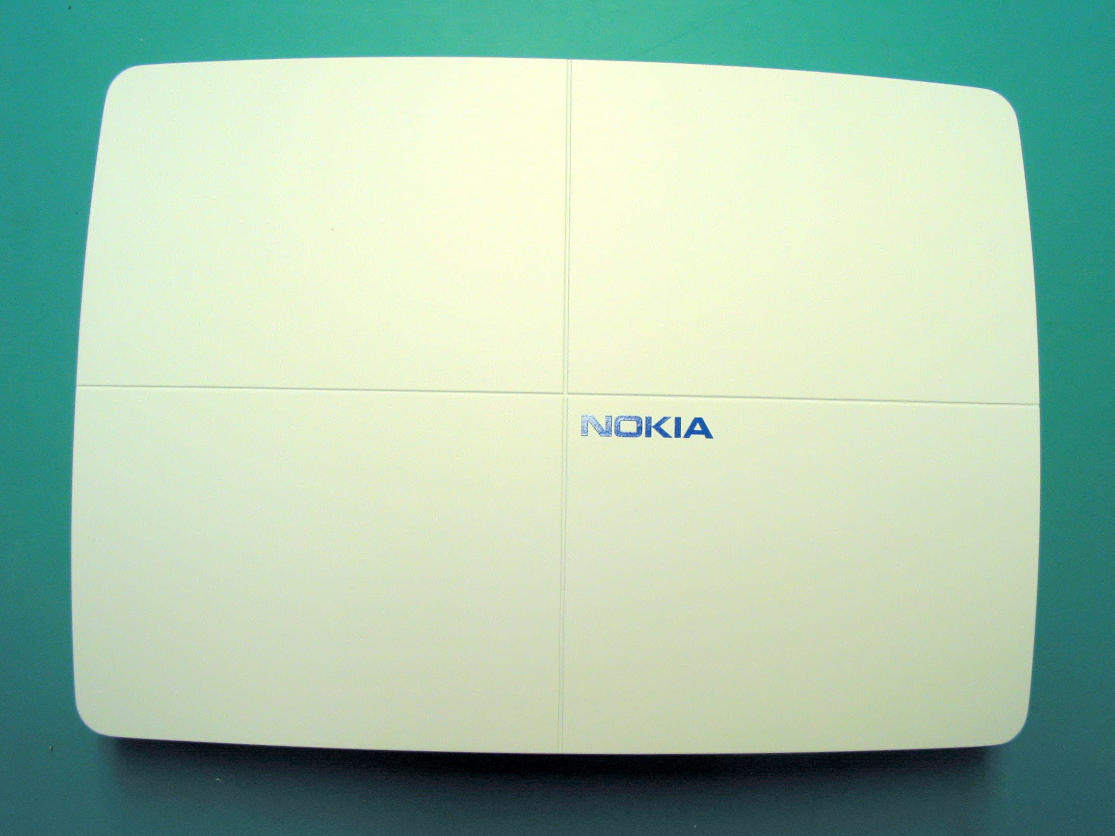
PURSSERIESGSMNA02
Apr 23, 2007S -BTS GSM Base Station
Equipment Class
PCB - PCS Licensed Transmitter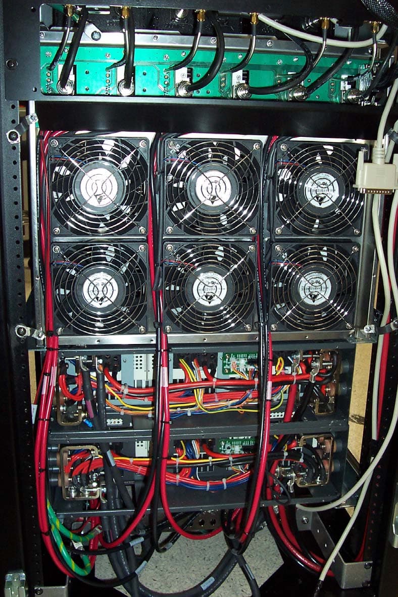
PURMCSERIESHP10
Mar 26, 2007MC Series High Power
Equipment Class
TNB - Licensed Non-Broadcast Station Transmitter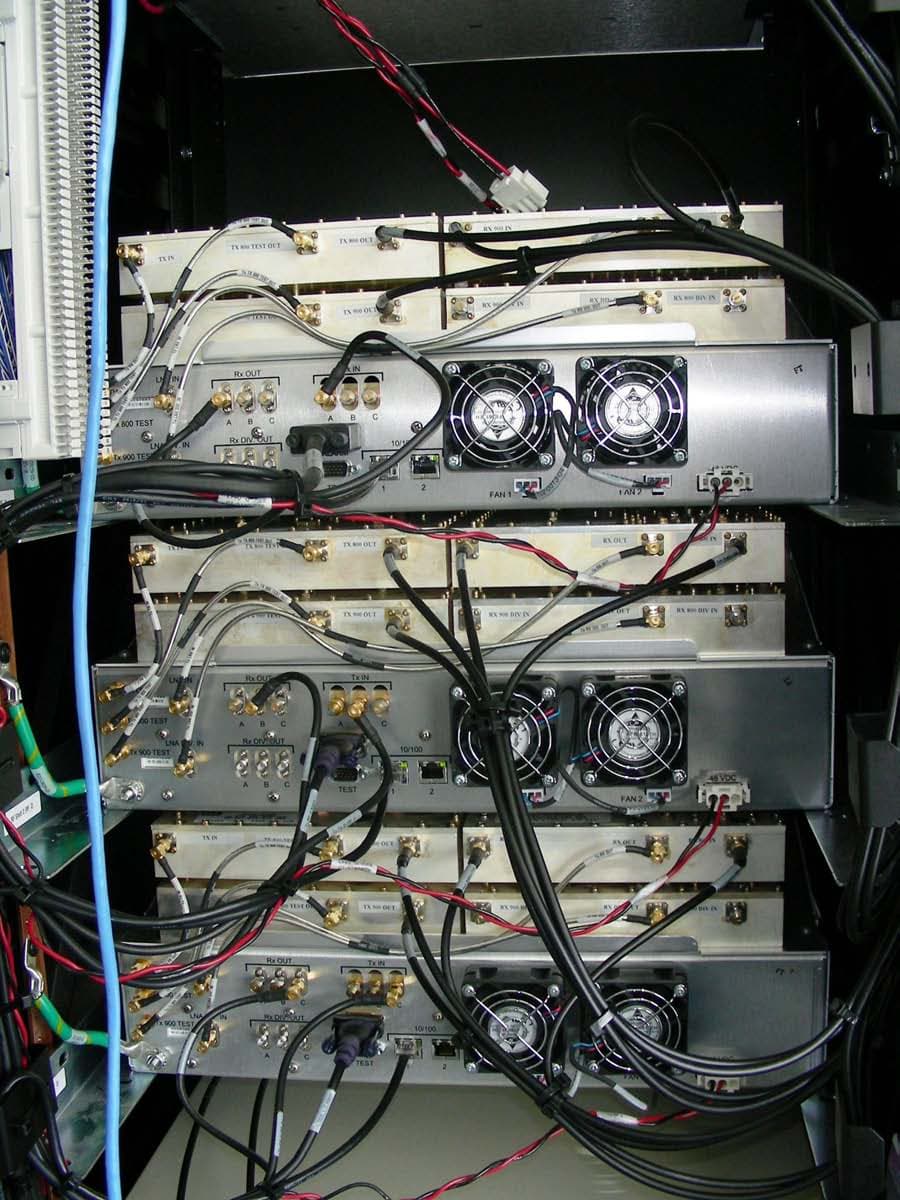
PURMCSERIESMP
Sep 30, 2006MC Series Mid Power
Equipment Class
TNB - Licensed Non-Broadcast Station Transmitter
PURMCRB10
Apr 16, 2006MCRB
Equipment Class
TNB - Licensed Non-Broadcast Station Transmitter
PURMCSERIES10
Mar 14, 2005MC-15
Equipment Class
TNB - Licensed Non-Broadcast Station Transmitter