PURMCSERIES10MC-15
RadioFrame Networks, Inc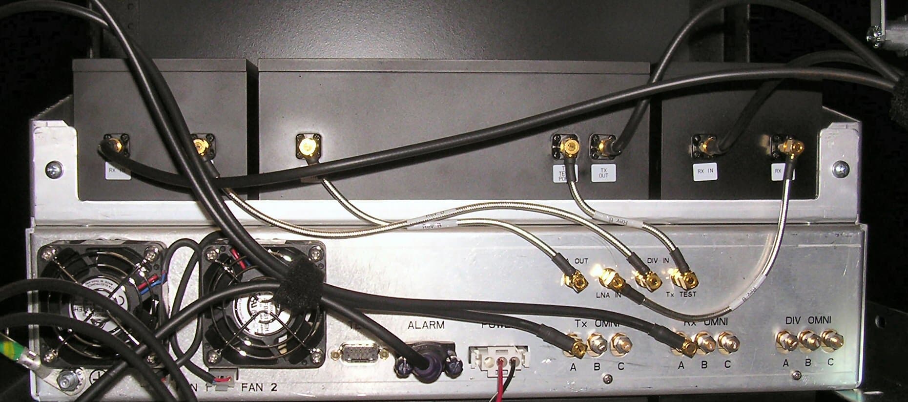
Click to zoom
Application Details
- Equipment Class
- TNB - Licensed Non-Broadcast Station Transmitter
- Date of Grant
- Mar 14, 2005
- Application Purpose
- Original Equipment
- Date of Application
- Mar 14, 2005
- Equipment Note
- MC-15
- Frequency Range
- 851.01250000 - 868.98750000
- Company
- RadioFrame Networks, Inc
- Country
- United States
Documents & Files
Document Text
Text extracted from the exhibit documents filed with the FCC. Open a document above to read the original.
Users Manual
RadioFrame Networks MC-Series System Installation & Testing December 20, 2004 998-4001-00 Rev B MC-Series System Installation & Testing ii RadioFrame Networks, Inc. Service Information This equipment complies with part 15 of the FCC Rules. Operation is subject to the two following conditions: This device may not cause harmful interference, and this device must accept any interference received, including interference that may cause undesired operation. This equipment has been tested and found to comply with the limits pursuant to part 90.691 of the FCC Rules. These limits are designed to provide reasonable protection against harmful interference when the equipment is operated in a commercial environment. Notices These installation standards have been prepared to provide Nextel Communications with general standards necessary to ensure that installed RadioFrame Networks equipment operates in accordance with the design parameters in the owned or leased buildings of Nextel Communications and its customers, and to make certain equipment is installed safely and efficiently. RadioFrame Networks reserves the right to revise this document for any reason, including, but not limited to, conformity with standards promulgated by various governmental or regulatory agencies, utilization of advances in the state of the technical arts, or to reflect changes in the design of equipment, techniques, or procedures described or referred to herein. Liability to anyone arising out of use or reliance upon any information set forth herein is expressly disclaimed, and no representation or warranties, expressed or implied, are made with respect to the accuracy or utility of any information set forth herein. Copyrights and Trademarks RadioFrame Networks, RadioBlade, and the RadioFrame Networks logo are trademarks or service marks, and RadioFrame is a registered trademark of RadioFrame Networks, Inc. You may not use these or any other RadioFrame Networks trademarks or service marks without the written permission of RadioFrame Networks, Inc. All other trademarks and trade names are the property of their respective owners. Throughout this publication, the terms RadioFrame Networks, RadioFrame and RFN signify RadioFrame Networks, Inc., and Nextel signifies Nextel Communications. MC-Series System Installation & Testing © Copyright 2004 RadioFrame Networks, Inc. All Rights Reserved. MC-Series System Installation & Testing RadioFrame Networks, Inc. iii Contents 1 Introduction.............................................................................................................................. 1 1.1 Record of Revisions ......................................................................................................... 1 1.2 References ....................................................................................................................... 1 1.3 General Safety Information .............................................................................................. 2 1.4 Repair and Technical Support.......................................................................................... 3 2 System Description ................................................................................................................. 5 2.1 MC-Series System Configuration..................................................................................... 6 2.2 RadioFrame Networks Hardware..................................................................................... 8 2.3 System Manager Software............................................................................................. 23 2.4 Non-RFN Hardware....................................................................................................... 24 2.5 Specifications .................................................................................................................25 3 Pre-Installation....................................................................................................................... 30 3.1 Site Planning ..................................................................................................................30 3.2 Scheduling / Logistics .................................................................................................... 33 3.3 MC-Series System Installation Kit.................................................................................. 33 3.4 iDEN Configuration ........................................................................................................ 34 4 Installation ............................................................................................................................. 35 4.1 Site Inspection................................................................................................................35 4.2 Receipt of Equipment ..................................................................................................... 35 4.3 Mounting the MC-Series System Cabinet ...................................................................... 36 4.4 Mounting Non-RFN Equipment in the MC-Series System Cabinet ............................... 36 4.5 Mounting Auxiliary Equipment........................................................................................ 40 4.6 Cabinet-to-Site Cabling .................................................................................................. 40 4.7 Intra-cabinet Cabling ...................................................................................................... 43 5 Final Checkout and Commissioning ................................................................................... 44 5.1 Prerequisites ..................................................................................................................44 5.2 Checkout Procedures..................................................................................................... 45 5.3 Initial Powering Procedure ................…
Text truncated - open the document above for the full version.
Cover Letter(s)
Northwest EMC TCB Approval Opinion Revision 05//02 RAFN0041 Information about the Applicant Applicant: Radioframe Networks, Inc. Address: 1120 112th Ave NE, Suite 600 City, State, Zip Bellevue, WA 98004 Test Requested By: Steve Peters Model: MC-15 FCC ID: PURMCSERIES10 Agent Radioframe Networks, Inc. Approval Type Certification Equipment Type Microcell cellular base station for iDEN radio. Rule Part 90.691 Overview This Base station operates in the 850 MHz ESMR Cellular service. See cover letter from applicant for further details. Findings Finding Cover Letter Please provide a cover letter that briefly describes the radio (e.g. Model 41233, 802.11(b) access point), the type of equipment approval that is being sought (e.g. Class II permissive change, or original certification), and the applicable rule parts. Also include any product specific FCC interpretations you may have received. Resolution A cover letter has been provided. Finding 47 Cfr 2.1033(C)(5) A block diagram showing the frequency of all oscillators in the device. The signal path and frequency shall be indicated at each block. The tuning range(s) and intermediate frequency(ies) shall be indicated at each block. A schematic diagram is also required for intentional radiators. The Block diagram meeting the requirements above has not been received. Resolution A block diagram has been provided Finding 47 Cfr 2.1033(c)9) Tune-up procedure over the power range, or at specific operating power levels. The Tune-up procedures are not in the package of information we have. Resolution An Installation Guide has been provided. Finding 47 Cfr 2.1033(C)(10) A schematic diagram and a description of all circuitry and devices provided for determining and stabilizing frequency, for suppression of spurious radiation, for limiting modulation, and for limiting power. The schematics appear to be incomplete. Resolution Schematics have been provided Northwest EMC TCB Approval Opinion Revision 05//02 RAFN0041 Finding 47 Cfr 2.1033(c)(10) Photographs (8x10) of the equipment of sufficient clarity to reveal equipment construction and layout, including meters, if any, and labels for controls and meters and sufficient views of the internal construction to define component placement and chassis assembly. Insofar as these requirements are met by photographs or drawings contained in instruction manuals supplied with the certification request, additional photographs are necessary only to complete the required showing. Please identify the radio on the photos and provide photos with the shields removed. Resolution Photographs have been provided Finding 47 Cfr 2.1033(c)(13) For equipment employing digital modulation techniques, a detailed description of the modulation system to be used, including the response characteristics (frequency, phase and amplitude) of any filters provided, and a description of the modulating wavetrain, shall be submitted for the maximum rated conditions under which the equipment will be operated. Please provide the required exhibit Resolution A theory of operation exhibit has been provided with this information included Finding 47 Cfr 15,21 The users manual or instruction manual for an intentional or unintentional radiator shall caution the user that changes or modifications not expressly approved by the party responsible for compliance could void the user's authority to operate the equipment. Could not locate statement in the manual provided Resolution A new user manual has been provided with the required information. Finding RF Exposure Exhibit • Incorrectly cited 15.247(b)(5) as the RF Exposure Requirement. • The maximum peak conducted power found in the test report is 22.2 dBm = 166 mW (see page 44 of 122 in Report-RAFN0042.pdf). Since the antenna gain in the RF exposure exhibit is declared to be 0 dBi, then the maximum peak radiated power would be 22.2 dBm EIRP • Table 1.1310 defines the general population limit as f/1500 = 0.567 mW/cm^2 (where f = 851 MHz) Not 1 mW/cm^2 • RF Estimates are incorrect. Notice that it does not demonstrate compliance. Resolution A new RF Exposure exhibit has been provided. Recommendation All items have been resolved and completed to my satisfaction; therefore I recommend this application for approval. Signature Northwest EMC TCB Approval Opinion Revision 05//02 RAFN0041 Opinion Specification Requirements Description 15.107 Conducted Power Line Emissions Opinion: The Equipment meets the intent specified by the requirements listed above Discussion: The Applicant has submitted test results in the form of a test report. Reference: Technical Report Specification Requirements Description FCC 15.109(b) Radiated Emissions Class A Opinion: The Equipment meets the intent specified by the requirements listed above. Discussion: The Applicant has submitted test results in the form of a test report Reference: Technical Report Specification Requirements Description 2.1055, 90.217 Frequency Stability Opinion: The Equipment meets the intent specified by the requirements listed above. Discussion: The Applicant has submitted test results in the form of a test report Reference: Technical Report Specification Requirements Description 90.691 Occupied Bandwidth Opinion: The Equipment meets the intent specified by the requirements listed above. Discussion: The Applicant has submitted test results in the form of a test report Reference: Technical Report Specification Requirements Description 2.1046 & 90.217 Output Power Opinion: The Equipment meets the intent specified by the requirements listed above. Discussion: The Applicant has submitted test results in the form of a test report. Reference: Technical Report Northwest EMC TCB Approval Opinion Revision 05//02 RAFN0041 Specification Requirements Description 2.1051 & 90.691 Spurious Conducted Emissions - Transmit Opinion: The Equipment meets the intent specified by the requirements listed above. Discussion: The Applicant has submitted test results in the form of a test report Refe…
Text truncated - open the document above for the full version.
Parts List/Tune Up Info
7-Dec-04Page 1 of 6 PST_CompItemID 101-0840-03 123-0680-01 510-0740-01 510-0740-99 510-0790-99 910-0840-01 asy-0840-04 200-49R9-0F 200-511-0J 201-0-0 201-100-0J 201-1001-0F 201-1002-0F 201-1003-0F 201-101-0J 201-102-0J 201-103-0J 201-112-0J 201-121-0J 201-124-0J 201-1272-0F 201-151-0J 201-153-0J 201-180-0J 201-1871-0F 201-220-0J 201-221-0J 201-222-0J 201-2492-0F 201-2552-0F 201-331-0J 201-332-0J 201-333-0J 201-360-0J 201-4422-0F 201-472-0J 201-4991-0F 201-4992-0F 201-5231-0F 201-680-0J 201-683-0J 201-7681-0F 201-821-0J 300-100-5J 300-101-5J 300-130-5J 300-1R8-5B 301-01R0-5C 301-01R2-5C 301-01R5-5C 301-02R2-5C 301-02R7-5C 301-0330-5J 301-03R0-5C 301-03R3-5C 301-04R7-5C 301-05R0-5C 301-06R8-5C 301-08R2-5C 301-101-5J 301-181-5J 301-220-5C 301-221-5J 301-270-5J 301-470-5J 311-102-5K 311-103-5K 311-223-3K 311-332-5K 311-471-5K 312-104-3K 312-334-1K 314-105-1K 331-104-3Z 332-105-1Z 334-106-9Z 334-475-1Z 391-105-9K 399-105-0M 401-5R6-0S-1 411-0240-0G-1 411-0270-0J-1 413-0391-0J 490-1R0-0J-1 491-0100-0J-2 491-0120-0J-1 491-0180-0G-1 491-0560-0G 491-0560-0J-1 491-0680-0J-1 491-102-0M 491-151-0K-1 491-1R5-0S 491-3R3-0S 491-6R8-0J 500-0100-00 500-0101-00 500-0111-00 500-0112-00 500-0150-00 500-0160-00 501-0220-00 501-0540-00 502-0556-00 504-0606-00 541-0001-00 600-0566-00 600-0580-00 601-0632-00 602-0901-00 602-0950-00 603-0001-00 603-0560-00 603-0605-00 603-0657-00 603-0670-00 603-0926-00 603-0927-00 603-0928-00 603-0932-00 603-0933-00 603-0936-00 603-1107-00 603-1108-00 604-0520-00 605-0761-00 605-0762-00 605-0764-00 605-0765-00 605-0766-00 605-0767-00 605-0768-00 605-0790-00 605-0871-00 605-0912-00 802-0110-02 920-0840-02 923-0840-01 928-0840-04 PCB-0840-02 924-0840-02 925-0840-02 926-0840-02 IMA_ItemNameText8PST_QtyIMA_Un PST_EffStartDate Two Port iDEN RadioBlade 10.00 Each Label Stock, 1 x 2, White Blank, Serial/PN/Mac Address 11.00 Each22-Sep-04 SHIELD, RADIOBLADE, TOP, iDEN B1.00 Each22-Sep-04 RadioBlade, Shield, iDEN, Top 11.00 Each30-Jul-04 RadioBlade, Shield, EU GSM, Bottom 41.00 Each22-Sep-01 SUB-LEVEL ASSEMBLY DRAWING, 101-0840-01 A0.00 Each22-Sep-04 Two Port iDEN RadioBlade v0.4 A1.00 Each28-Oct-04 49.9, 1%, 0402 12.00 Each20-Jul-04 510, 0402, 5% 11.00 Each20-Jul-04 0, 0603 122.00 Each20-Jul-04 10, +/-5%, 0603 11.00 Each20-Jul-04 1.00K, +/-1%, 0603 111.00 Each20-Jul-04 10.0K, +/-1%, 0603 112.00 Each20-Jul-04 100K, 1%, 0603 14.00 Each20-Jul-04 100, +/-5%, 0603 13.00 Each20-Jul-04 1K, +/-5%, 0603 16.00 Each20-Jul-04 10K, +/-5%, 0603 119.00 Each20-Jul-04 1.1k, +/-5%, 0603 31.00 Each20-Jul-04 120, +/-5%, 0603 11.00 Each20-Jul-04 120k, +/-5%, 0603 12.00 Each06-Oct-04 12.7k, 1%, 0603 12.00 Each20-Jul-04 150, +/-5%, 0603 14.00 Each20-Jul-04 15K, +/-5%, 0603 21.00 Each20-Jul-04 18, +/-5%, 0603 21.00 Each20-Jul-04 1.87K, 1%, 0603 18.00 Each20-Jul-04 22, +/-5%, 0603 14.00 Each20-Jul-04 220, +/-5%, 0603 121.00 Each20-Jul-04 2.2K, +/-5%, 0603 16.00 Each20-Jul-04 24.9k, 1%, 0603 13.00 Each20-Jul-04 25.5K, +/-1%, 0603 35.00 Each20-Jul-04 330, +/-5%, 0603 11.00 Each20-Jul-04 3.3K, +/-5%, 0603 21.00 Each20-Jul-04 33K, +/-5%, 0603 11.00 Each20-Jul-04 36, +/-5%, 0603 23.00 Each20-Jul-04 44.2k , 1%, 0603 14.00 Each20-Jul-04 4.7K, +/-5%, 0603 14.00 Each20-Jul-04 4.99K, +/-1%, 0603 111.00 Each20-Jul-04 49.9K, +/-1%, 0603 14.00 Each20-Jul-04 5.23K, +/-1%, 0603 22.00 Each20-Jul-04 68, +/-5%, 0603 33.00 Each20-Jul-04 68K, +/-5%, 0603 41.00 Each20-Jul-04 7.68k, 1%, 0603 16.00 Each20-Jul-04 820, +/-5%, 0603 21.00 Each20-Jul-04 10pF, 50V, NPO, +/-5%, 0402 21.00 Each20-Jul-04 100pF, 50V, NPO, +/-5%, 0402 25.00 Each20-Jul-04 13pF, 50V, NPO, 5%, 0402 12.00 Each20-Jul-04 1.8pF, 50V, NPO, +/-0.1pF, 0402 11.00 Each20-Jul-04 Cap, 1.0pF, 50V, NP0, +/-0.25pF, 0603 11.00 Each20-Jul-04 Cap, 1.2pF, 50V, NP0, +/-0.25pF, 0603 11.00 Each20-Jul-04 Cap, 1.5pF, 50V, NP0, +/-0.25pF, 0603 11.00 Each20-Jul-04 2.2pF, 50V, NPO, +/-0.25pF, 0603 34.00 Each20-Jul-04 Cap, 2.7pF, 50V, NP0, +/-0.25pF, 0603 12.00 Each20-Jul-04 33pF, 50V, NPO, +/-5%, 0603 22.00 Each20-Jul-04 3.0pF, 50V, NPO, +/-0.25pF, 0603 11.00 Each20-Jul-04 3.3pF, 50V, NPO, +/-0.25pF, 0603 31.00 Each20-Jul-04 4.7pF, 50V, NPO, +/-0.25pF, 0603 23.00 Each20-Jul-04 5.0pF, 50V, NPO, +/-0.25pF, 0603 32.00 Each20-Jul-04 6.8pF, 50V, NPO, +/-0.25pF, 0603 11.00 Each20-Jul-04 8.2pF, 50V, NPO, +/-0.25pF, 0603 11.00 Each20-Jul-04 100pF, 50V, NPO, +/-5%, 0603 236.00 Each20-Jul-04 180pF, 50V, NPO, +/-5%, 0603 228.00 Each20-Jul-04 22pF, 50V, NPO, +/-0.25pF, 0603 16.00 Each20-Jul-04 220pF, 50V, NPO, +/-5%, 0603 23.00 Each20-Jul-04 27pF, 50V, NPO, +/-5%, 0603 12.00 Each20-Jul-04 47pF, 50V, NPO, +/-5%, 0603 28.00 Each20-Jul-04 1000pF, 50V, X7R, +/-10%, 0603 211.00 Each20-Jul-04 .01uF, 50V, X7R, +/-10%, 0603 334.00 Each20-Jul-04 0.022uF, 25V, X7R, +/-10%, 0603 21.00 Each20-Jul-04 3300pF, 50V, X7R, +/-10%, 0603 12.00 Each20-Jul-04 470pF, 50V, X7R, +/-10%, 0603 24.00 Each20-Jul-04 0.1uF, 25V, X7R, +/-10%, 0805 31.00 Each20-Jul-04 0.33uF, 16V, X7R, +/-10%, 0805 23.00 Each20-Jul-04 1uF, 16V, X7R, +/-10%, 1206 11.00 Each20-Jul-04 0.1uF, 25V, Y5V, +80%-20%, 0603 251.00 Each20-Jul-04 1uF, 16V, Y5V, +80%-20%, 0805 215.00 Each20-Jul-04 10uF, 6.3V, Y5V, +80%-20%, 1206 115.00 Each20-Jul-04 4.7uF, 16V, Y5V, +80%-20%, 1206 12.00 Each20-Jul-04 1uF, 0603, 10%, X5R, 6.3V Capacitor 13.00 Each20-Jul-04 1.0uF, 10V, +/-20%, 2x1.25mm 22.00 Each20-Jul-04 Ind, Ceramic, 5.6nH, +/-0.3nH, 0603, Toko 11.00 Each20-Jul-04 Ind, WW, 24nH, +/-2%, 0603, Toko 11.00 Each20-Jul-04 27nH, +/-5%, 0603 12.00 Each20-Jul-04 390nH, +/-5%, 1008 12.00 Each20-Jul-04 1nH, +/-5%, 0402, Pulse 21.00 Each20-Jul-04 10nH, +/-5%, 0603, Toko 26.00 Each20-Jul-04 12nH, +/-5%, 0603, Murata 12.00 Each20-Jul-04 18nH, +/-2%, 0603, Pulse 11.00 Each20-Jul-04 56nH +/-2%, 0603 21.00 Each20-Jul-04 56nH, +/-5%, 0603, Murata 22.00 Each20-Jul-04 68nH, +/-5%, 0603, Murata 21.00 Each20-Jul-04 1uH, +/-25%, 0603, ferrite bead 28.00 Each20-Jul-04 150nH, +/-10%, 0603, Taiyo Yuden 23.00 Each20-Jul-04 1.5nH, ±0.3nH, 0603 21.00 Each20-Jul-04 3.3nH, ±0.3nH, 0603 21.00 E…
Text truncated - open the document above for the full version.
RF Exposure Info
Compliance with 47 CFR 2.1091 The EUT will be professionally installed and can only be used with a separation distance of 25centimeters or greater between the antenna and the body of the user or nearby persons and can therefore be considered a mobile transmitter per 47CFR 2.1091 (b). The EUT has six antenna ports. Three antenna ports are for transmit and three for receive. The Base Station can accommodate 24 radios for a total and can be configured for either 3 sectors with 8 iDEN transmitters (FCC ID: PURMCSERIES10) per sector or an Omni system with 20 iDEN transmitters (FCC ID: PURMCSERIES10). The maximum peak power was measured to be 166 mW (EIRP) per channel for FCC ID: PURMCSERIES10. The EUT meets the requirement that it will be operated in a manner that ensures that the public is not exposed to radio frequency energy levels in excess of the Commission’s guidelines (ref. 47 CFR 1.1307, 1.1310, 2.1091 and 2.1093. also OET Bulletin 65, Supplement C). The MPE estimates are as follows: Table 1 in 47 CFR 1.1310 defines the maximum permissible exposure (MPE) for the general population as (f/1500) mW/cm 2 . The exposure level at a 25 cm distance from the EUT’s transmitting antenna is calculated using the general equation: S = (PG)/4πR 2 Where: S = power density (mW/cm 2 ) P = power input to the antenna (mW) G = numeric power gain relative to an isotropic radiator R = distance to the center of the radiation of the antenna (25 cm = distance for MPE estimates) PG = EIRP Solving for S, the maximum power densities 25 cm from the transmitting antennas are summarized in the following tables: MPE Estimates for Self Co-located Device Antenna Type Antenna Part No. Transmit Frequency Max Peak Conducted Output Power Antenna Gain Minimum Antenna Cable Loss Power Density @ 25 cm General Population Exposure Limit from 1.1310 Ratio of Power Density to the Exposure Limit (MHz)(mW)(dBi)(dB) (mW/cm 2 )(mW/cm 2 ) Omni860166000.0210.5673333330.037 Worst Case Ratio of Power Density to the Exposure Limit = 0.058 Per Note 24 shown below, the Sum of Worst Case Power Ratios cannot exceed 1.0 iDEN Radio Worst Case Ratio of Power Density to the Exposure Limit Maximum Number of co - located Radios Sum of Worst Case Ratios (Power Density to the Exposure Limit) FCC Limit for Sum of Worst Case Ratios 0.03725200.745091.0PASS iDEN Radio FCC ID: PURMCSERIES10 Worst Case Co-located Exposure Condition Excerpts from TCB Training, April 3, 2002, “Mobile Transmitters”, Slide 6: “Devices operating in multiple frequency bands When RF exposure evaluation is required for TCB approval o Separate antennas – estimated minimum separation distances may be considered for the frequency bands that do not require evaluation or TCB approval, however, the estimated distance should take into account the effect of co-located transmitters. (Note 24) Note 24 According to multiple frequency exposure criteria, the ratio of field strength or power density to the applicable exposure limit at the exposure location should be determined for each transmitter and the sum of these ratios must not exceed 1.0 for the location to be compliant .” The sum of the worst case ratio of power density to the exposure limit is less than 1.0. Therefore, the co-location configuration is compliant.
Test Report
Radioframe Networks, Inc. MC Series December 01, 2004 Report No. RAFN0042 Report Prepared By www.nwemc.com 1-888-EMI-CERT © 2004 Northwest EMC, Inc 22975 NW Evergreen Parkway Suite 400 Hillsboro, Oregon 97124 Certificate of Test Issue Date: December 01, 2004 Radioframe Networks, Inc. Model: MC Series Emissions Specification Test Method Pass Fail FCC 15.107 AC Powerline Conducted Emissions (Receive Mode):2004 ANSI C63.4:2003 FCC 15.109 Radiated Emissions (Receive Mode):2004 ANSI C63.4:2003 FCC 15.111 Conducted Spurious Emissions (Receive Mode):2004 ANSI C63.4:2003 FCC 90.217 and FCC 2.1055 Frequency Stability:2004 TIA/EIA-603:2001 FCC 90.691 Occupied Bandwidth / Emission Mask:2004 TIA/EIA-603:2001 FCC 90.217 and FCC 2.1046 Output Power:2004 TIA/EIA-603:2001 FCC 90.691 and FCC 2.1051 Spurious Conducted Emissions:2004 TIA/EIA-603:2001 FCC 90.691 and FCC 2.1053 Spurious Radiated Emissions:2004 TIA/EIA-603:2001 Modifications made to the product See the Modifications section of this report Test Facility • The measurement facility used to collect the data is located at: Northwest EMC, Inc.; 22975 NW Evergreen Parkway, Suite 400; Hillsboro, OR 97124 Phone: (503) 844-4066 Fax: 844-3826 This site has been fully described in a report filed with and accepted by the FCC (Federal Communications Commission) and Industry Canada. Approved By: Don Facteau, IS Manager This report must not be used to claim product certification, approval, or endorsement by NVLAP, NIST, or any agency of the federal government of the United States of America. Product compliance is the responsibility of the client, therefore the tests and equipment modes of operation represented in this report were agreed upon by the client, prior to testing. This Report may only be duplicated in its entirety. The results of this test pertain only to the sample(s) tested, the specific description is noted in each of the individual sections of the test report supporting this certificate of test. Northwest EMC Revision History Revision 05/05/03 Revision Number Description Date Page Number 00 None Northwest EMC Accreditations and Authorizations Revision 01/04/05 FCC: Accredited by NVLAP for performance of FCC radio, digital, and ISM device testing. Our Open Area Test Sites, certification chambers, and conducted measurement facilities, have been fully described in reports filed with the FCC and accepted by the FCC in letters maintained in our files. Northwest EMC has been accredited by ANSI to ISO / IEC Guide 65 as a product certifier. We have been designated by the FCC as a Telecommunications Certification Body (TCB). This allows Northwest EMC to certify transmitters to FCC specifications in accordance with 47 CFR 2.960 and 2.962. NVLAP: Northwest EMC, Inc. is recognized under the United States Department of Commerce, National Institute of Standards and Technology, National Voluntary Laboratory Accreditation Program for satisfactory compliance with the requirements of ISO/IEC 17025 for Testing Laboratories. The NVLAP accreditation encompasses Electromagnetic Compatibility Testing in accordance with the European Union EMC Directive 89/336/EEC, ANSI C63.4, MIL- STD 461E, DO-160D and SAE J1113. Additionally, Northwest EMC is accredited by NVLAP to perform radio testing in accordance with the European Union R&TTE Directive 1999/5/EEC, the requirements of FCC, and the RSS radio standards for Industry Canada. 200629-0 200630-0 200676-0 Industry Canada: Accredited by NVLAP for performance of Industry Canada RSS and ICES testing. Our Open Area Test Sites and certification chambers comply with RSS 212, Issue 1 (Provisional) and have been filed with Industry Canada and accepted. Northwest EMC has been accredited by ANSI to ISO / IEC Guide 65 as a product certifier. We have been designated by NIST and recognized by Industry Canada as a Certification Body (CB) per the APEC Mutual Recognition Arrangement (MRA). This allows Northwest EMC to certify transmitters to Industry Canada technical requirements. CAB: Designated by NIST and validated by the European Commission as a Conformity Assessment Body (CAB) to conduct tests and approve products to the EMC directive and transmitters to the R&TTE directive, as described in the U.S. - EU Mutual Recognition Agreement TÜV Product Service: Included in TUV Product Service Group's Listing of Recognized Laboratories. It qualifies in connection with the TUV Certification after Recognition of Agent's Testing Program for the product categories and/or standards shown in TUV's current Listing of CARAT Laboratories available from TUV. A certificate was issued to represent that this laboratory continues to meet TUV's CARAT Program requirements. Certificate No. USA0401C TÜV Rheinland: Authorized to carryout EMC tests by order and under supervision of TÜV Rheinland. This authorization is based on "Conditions for EMC-Subcontractors" of November 1992. Northwest EMC Accreditations and Authorizations Revision 01/04/05 NEMKO: Assessed and accredited by NEMKO (Norwegian testing and certification body) for European emissions and immunity testing. As a result of NEMKO's laboratory assessment, they will accept test results from Northwest EMC, Inc. for product certification (Authorization No. ELA 119). Technology International: Assessed in accordance with ISO Guide 25 defining the general international requirements for the competence of calibration and testing laboratories and with ITI assessment criteria LACO196. Based upon that assessment Interference Technology International, Ltd., has granted approval for specifications implementing the EU Directive on EMC (89/336/EEC and amendments). The scope of the approval was provided on a Schedule of Assessment supplied with the certificate and is available upon request. Australia/New Zealand: The National Association of Testing Authorities (NATA), Australia has been appointed by the ACA as an accreditation body to accredit test laboratories and competent bodies for EMC standards. Accredited test …
Text truncated - open the document above for the full version.
Contact Information
Applicant
Dean Busch(Sr. Compliance Engineer)
Test Firm
Northwest EMC, Inc.Greg Kiemel
Technical Specifications
| # | Rule Parts | Frequency Range | Power Output | Emission | Tolerance |
|---|---|---|---|---|---|
| 1 | 90.691 | 851.0125 MHz - 868.9875 MHz | 166.00 mW | 25K0D7W | 0.0800000000 ppm |
Other Applications from RadioFrame Networks, Inc
PURSSERIESGSMNA02
Apr 23, 2007S -BTS GSM Base Station
Equipment Class
PCB - PCS Licensed Transmitter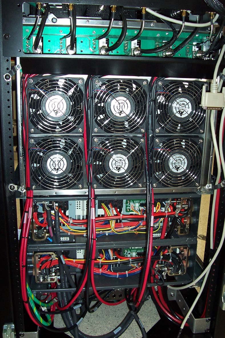
PURMCSERIESHP10
Mar 26, 2007MC Series High Power
Equipment Class
TNB - Licensed Non-Broadcast Station Transmitter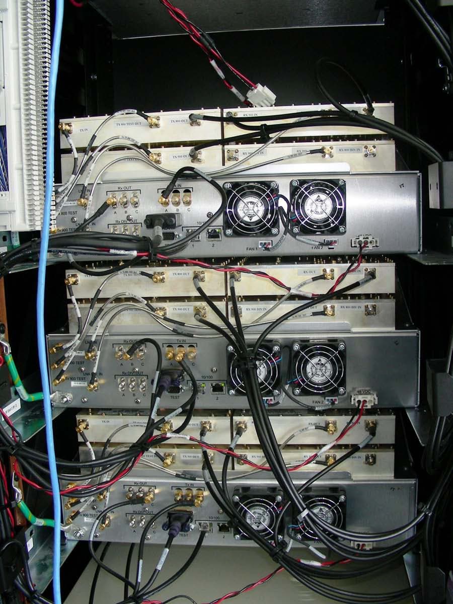
PURMCSERIESMP
Sep 30, 2006MC Series Mid Power
Equipment Class
TNB - Licensed Non-Broadcast Station Transmitter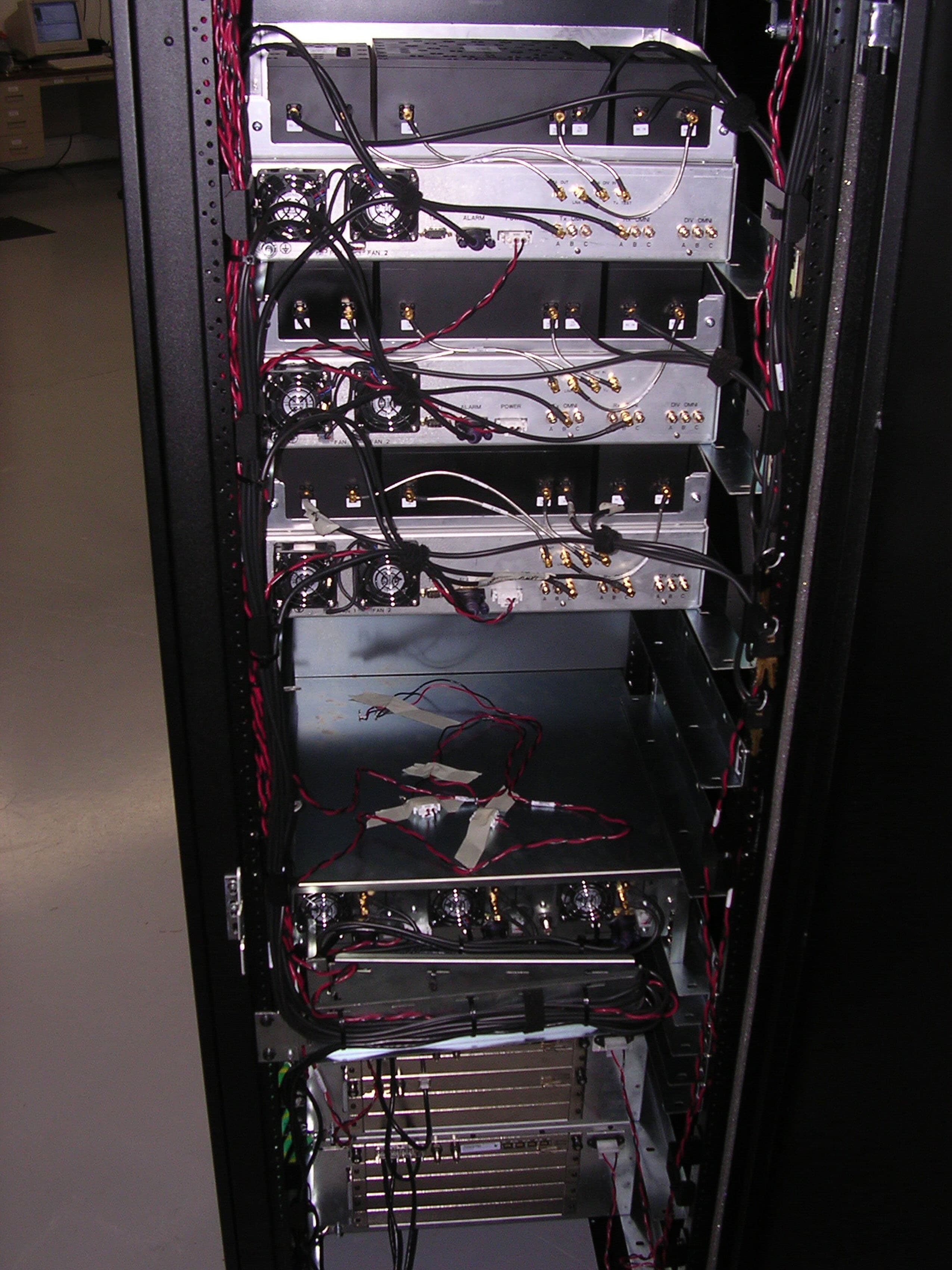
PURMCRB10
Apr 16, 2006MCRB
Equipment Class
TNB - Licensed Non-Broadcast Station Transmitter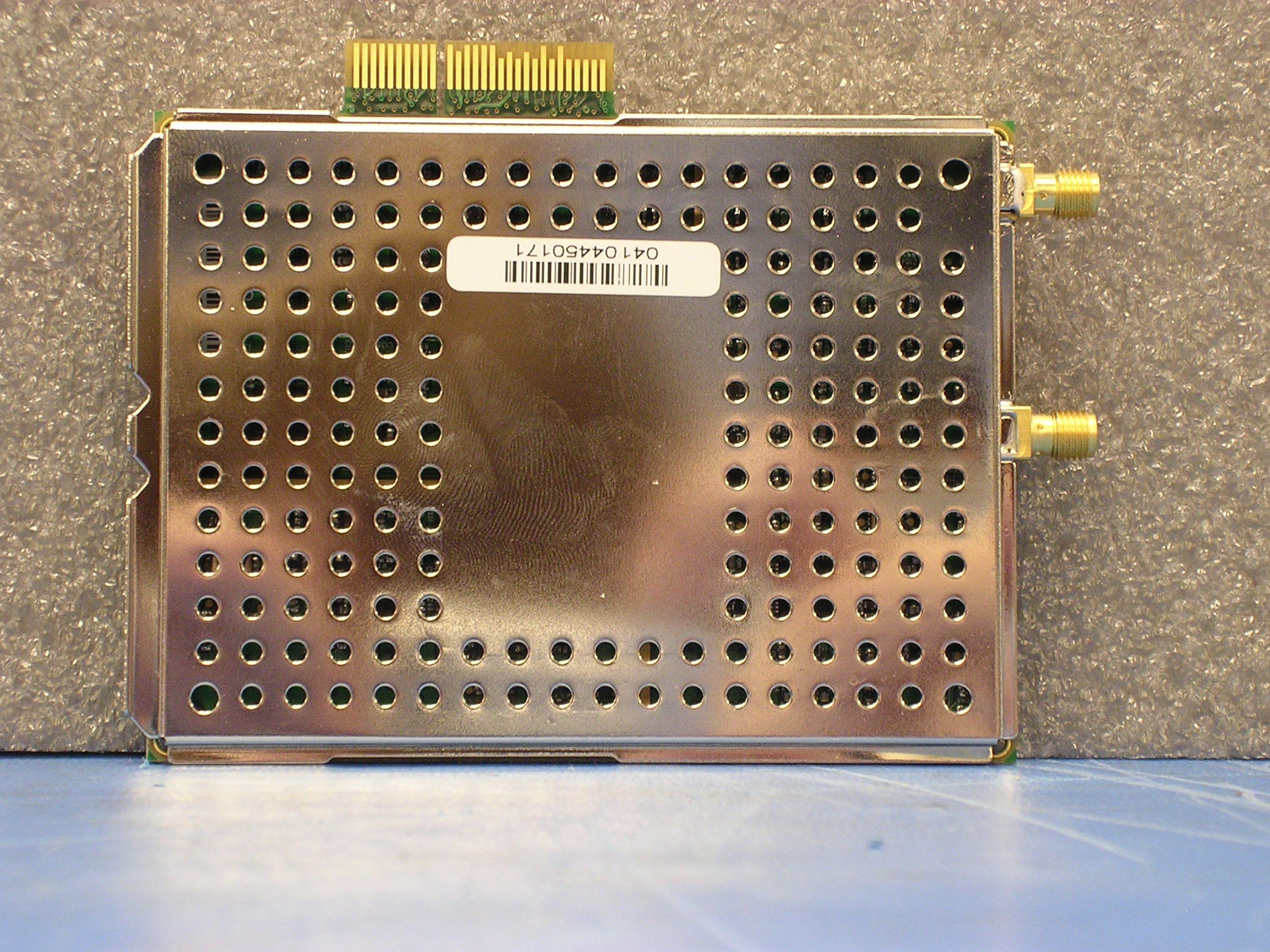
PURBSERIESGSMNA10
May 03, 2005B-Series GSM 1.0
Equipment Class
PCB - PCS Licensed Transmitter