PURSSERIESGSMNA02S -BTS GSM Base Station
RadioFrame Networks, Inc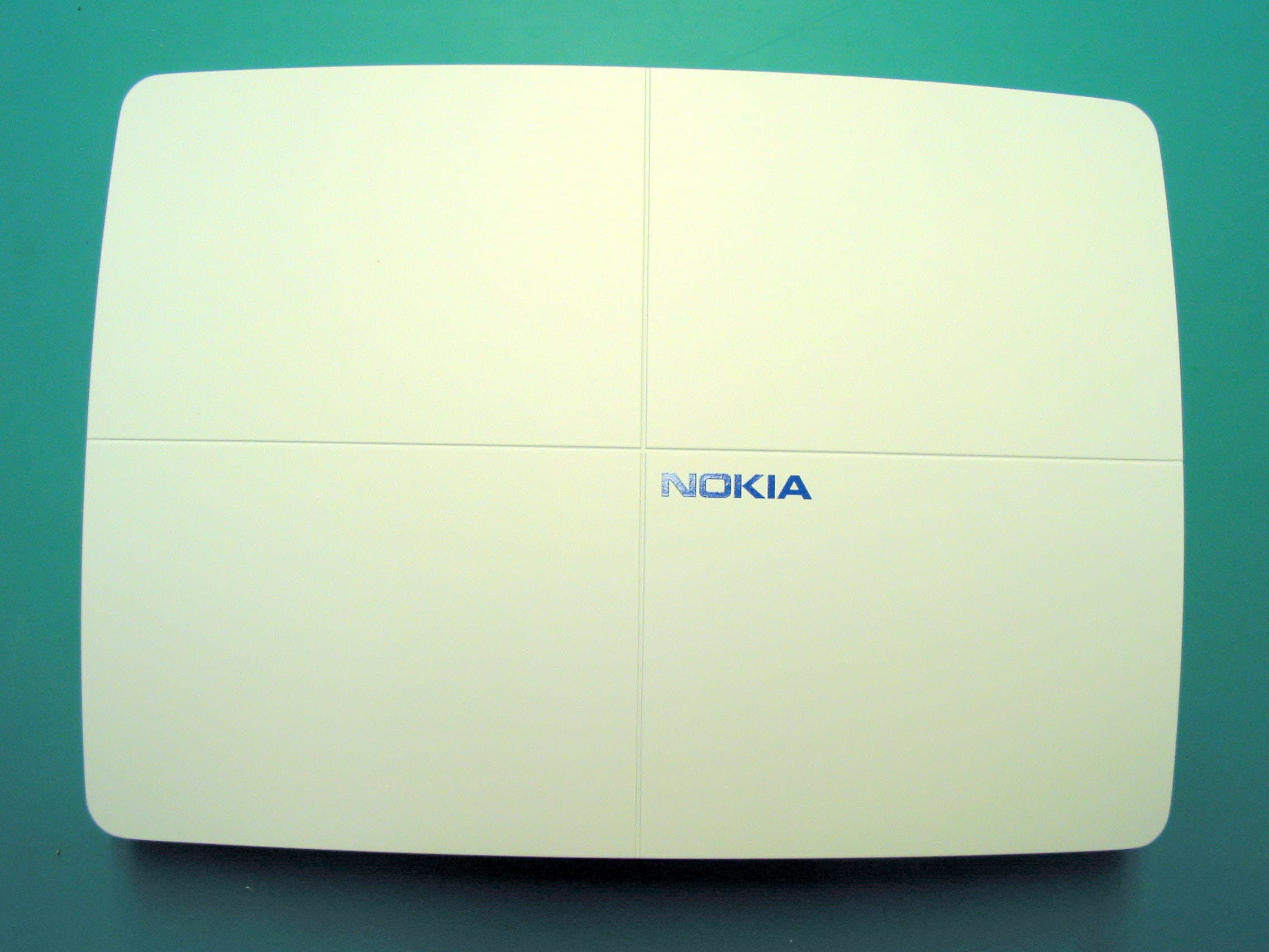
Click to zoom
Application Details
- Equipment Class
- PCB - PCS Licensed Transmitter
- Date of Grant
- Apr 23, 2007
- Application Purpose
- Original Equipment
- Date of Application
- Apr 23, 2007
- Equipment Note
- S -BTS GSM Base Station
- Frequency Range
- 1930.40000000 - 1989.60000000
- Company
- RadioFrame Networks, Inc
- Country
- United States
Documents & Files
Document Text
Text extracted from the exhibit documents filed with the FCC. Open a document above to read the original.
Users Manual
User Reference S-Series GSM/GPRS Radio Base Station 931-1002-01 Rev. A Service Information This equipment complies with part 15 of the FCC Rules. Operation is subject to the two following conditions: This device may not cause harmful interference, and this device must accept any interference received, including interference that may cause undesired operation. This equipment has been tested and found to comply with the limits pursuant to 47 CFR Part 22 subpart H and Part 24 Subpart E of the FCC Rules. These limits are designed to provide reasonable protection against harmful interference when the equipment is operated in a commercial environment. Notices RadioFrame Networks reserves the right to revise this document for any reason, including, but not limited to, conformity with standards promulgated by various governmental or regulatory agencies, utilization of advances in the state of the technical arts, or to reflect changes in the design of equipment, techniques, or procedures described or referred to herein. Liability to anyone arising out of use or reliance upon any information set forth herein is expressly disclaimed, and no representation or warranties, expressed or implied, are made with respect to the accuracy or utility of any information set forth herein. Copyrights and Trademarks RadioFrame Networks is a trademark or service mark, and RadioFrame and the RadioFrame Networks logo are registered trademarks of RadioFrame Networks, Inc. All other trademarks and trade names are the property of their respective owners. S-Series GSM/GPRS Radio Base Station © Copyright 2006 RadioFrame Networks, Inc. All Rights Reserved. ii S-Series GSM/GPRS Radio Base Station RadioFrame Networks, Inc. RadioFrame Networks, Inc. 9461 Willows Road NE, Suite 100 Redmond, WA 98052 USA Tel: +1-1-425-278-2780 Fax: +1-1-425-278-2781 www.radioframenetworks.com RadioFrame Networks, Inc. S-Series GSM/GPRS Radio Base Station iii Table of Contents 1 Getting to Know Your Radio Base Station 5 2 Minimum Requirements Error! Bookmark not defined. 3 The S1 Indicators, Connectors and Reset Button 6 4 Connecting the S1 7 5 Configuring the S1 Router 9 Appendix A Troubleshooting 16 Figures Figure 1 Front Indicators 6 Figure 2 Back Connectors and the Reset Button 6 Figure 3 Typical Setup 7 Figure 4 S1 Connections 8 Figure 5 S1 Router Login 9 Figure 6 Sample Automatic Setup Performed 10 Figure 7 DHCP Server Setup 11 Figure 8 Advanced Routing 12 Figure 9 Firewall: Add Rule 13 Figure 10 Port Range Forwarding 14 Figure 11 Status Screen 15 Tables Table 1 Status Screen and S1 Factory Defaults 15 4 S-Series GSM/GPRS Radio Base Station RadioFrame Networks, Inc. CAUTION: Safety Instructions Read and follow these instructions when connecting and using your base station. • Maintain a distance of at least 20 cm between persons and a functioning radio base station. • Do not store or use the radio base station in locations that are exposed to heat, direct sunlight, excessive dust, or extreme cold. Keep it away from heaters, stoves, fireplaces, and other sources of heat. • Only a qualified technician should open the radio base station case. Do not insert anything into the case openings or touch the inside of the case to avoid damage. • Do not expose the radio base station to liquids. You may dust the base station with a damp cloth occasionally, being sure not to allow moisture to get inside. • Always be sure that your base station power transformer is rated for the AC power available in your location. • Locate the radio base station near an accessible electrical outlet. Ensure that power and data cables are not located where they can be stepped on or tripped over. If the power cable has been damaged, do not use it. When connecting and disconnecting cables, be sure to grasp the plug and not the cable. Be careful to pinch the locking clip when disconnecting any Ethernet cable. • Openings in the radio base station case are provided for ventilation. To prevent overheating, these openings must not be blocked or covered. Do not locate the base station on a soft surface such as a blanket because doing so may block the openings on the bottom of the case. If you place the base station in a bookcase or other enclosed space, be sure to provide adequate ventilation and air flow. Regulatory Notices Electromagnetic Interference (EMI) is any signal or emission, radiated in free space or conducted along power or signal leads, that endanger the function of a radio navigation or other safety service or seriously degrades, obstructs, or repeatedly interrupts a licensed radio communications service. Radio Communications services include but are not limited to AM/FM commercial broadcast, CE Notice <<To Be Supplied>> RadioFrame Networks, Inc. S-Series GSM/GPRS Radio Base Station 5 1 Getting to Know Your Radio Base Station Welcome The S1 GSM/GPRS Radio Base Station is the link between your cell phone (or your data card) and your service provider, providing your own personal island of coverage. It has a network connection for Internet access through your cable or DSL modem. There’s also a router inside and four LAN (local area network) ports for sharing connectivity with multiple computers. To create your cell radio link, install and set up the base station. You won’t find a complicated configuration script because the base station finds your cell service provider across the Internet by itself! (This assumes, of course that your cable or DSL modem is “talking” to its ISP, or Internet service provider. Please make sure this step is taken before you attempt to get the S1 base station working; you will need to arrange service and make sure it is working by contacting the ISP or your cellular service provider.) Once you have confirmed Internet access through your cable or DSL modem, the Quick Install Guide gives you all the information you need to get on the air. This reference contains much more information in case, for example, you want to do special configuration o…
Text truncated - open the document above for the full version.
Cover Letter(s)
Northwest EMC TCB Compliance Opinion Rev. 9/15/03 RAFN0069 Information about the Applicant Company Name Radioframe Networks, Inc. Grantee Stephen J. Peters Address 9461 Willows Road NE, Suite 100 City, State, Zip Redmond, WA 98052 Job Number RAFN0069 Model S -BTS GSM Base Station FCC ID PURSSERIESGSMNA02 Agent None Approval Type Original Equipment Class PCB PCS Licensed Transmitter Rule Part 22H, 24E Overview A base station transceiver designed for use in the GSM 800 MHz Cellular band FCC Part 22H from 869.2 to 893.8 MHz with 102.5 mW maximum output power, in the GSM 1900 MHz band FCC Part 24E from 1930.4 to 1986.6 MHz with an output power of 196.6 mW. Recommendation All items have been resolved and completed to my satisfaction; therefore I recommend this application for approval. Signature Dave Tolman, TCB Committee 4/23/2007
External Photos
S-1 Chassis front S-1 Chassis rear S-1 Chassis top S-1 Chassis bottom S-1 Chassis right side S-1 Chassis left side
ID Label/Location Info
REVISIONS REV CO DESCRIPTION OF CHANGE DRAWN BY DATE APPR. B UPDATE SERIAL NUMBER SEQUENCE, ADD DATE CODE DMD 2/23/07 C UPDATE SOURCE CODE AND DATE CODE, ADD RELEASE NUMBER DMD 3/13/07 D ADD FCC IDENTIFICATION TO LABEL DMD 4/18/07 NOTES: UNLESS OTHERWISE SPECIFIED 1. MATERIAL: PERMANENT WHITE POLYESTER WITH PRESSURE SENSITIVE ADHESIVE. BRADY LABEL STOCK THT-19-422-1 OR RFN APPROVED EQUIVALENT. 2. PRINT: BLACK PERMANENT INK, USING BRADY RIBBON STOCK #R6000 OR RFN APPROVED EQUIVALENT. 3. BARCODE FORMAT: CODE 39. 4. LABEL SIZE: 2”H X 3”W. 5. REFERENCE CUSTOMERS LABELING REQUIREMENTS. 6. ALL PARTS, MATERIALS AND FINISHES MUST BE RoHS COMPLIANT. ALL INVOLVED PARTIES IN THE MAKING OF THESE PARTS MUST PROVIDE STATEMENTS OF RoHS COMPLIANCE TO RADIOFRAME NETWORKS PRIOR TO MANUFACTURING FOR APPROVAL. THIS DOCUMENT, AND THE PROPRIETARY TRADE SECRET AND CONFIDENTIAL INFORMATION IT CONTAINS, ARE THE PROPERTY OF RADIOFRAME NETWORKS. DO NOT COPY, DISTRIBUTE, DISCLOSE, OR USE IN ANY MANNER WITHOUT THE PRIOR WRITTEN CONSENT OF RADIOFRAME NETWORKS. APPROVALS DATE DRAWN D. DUVALL 2/7/07 TITLE: LABEL, CERTIFICATION AND INFORMATION, S1, NA, LEAD FREE (NT) CHECKED DWG NAME: 123-0028-R01 REV. D UNLESS OTHERWISE SPECIFIED DIMENSIONS ARE IN INCHES TOLERANCES ARE: LINEAR: ANGULAR: .X ± 0.1 ± 0.5° .XX ± 0.02 .XXX ± 0.010 9461 WILLOWS RD NE, SUITE 100 REDMOND, WA 98052 ISSUED MATERIAL: SCALE: N/A DO NOT SCALE DRAWING SIZE A THIRD ANGLE PROJECTION APPROVED FINISH: SHEET 1 OF 1 RADIOFRAME NETWORKS ™ , INC. PICO BTS 850 & 1900MHz (US) FCC ID# PURSSERIESGSMNA02 NT0115AA PEC: NT0115AA RR LBNNTMJYYYWWNNNN S/N: LBNNTMJYYYWWNNNN 0003E0XZZZZZMAC: 0003E0XZZZZZ MADE IN U.S.A. 20396 WWYY
Internal Photos
S-1 Top S-1 Top with RF shields installed S-1 Bottom S-1 Bottom with RF shield removed S-1 Power and Ethernet Connectors S-1 Tx SMA connector
RF Exposure Info
Compliance with 47 CFR 15.247(b)(5) “Systems operating under the provisions of this section shall be operated in a manner that ensures that the public is not exposed to radio frequency energy levels in excess of the Commission's guidelines. See § 1.1307(b)(1) of this Chapter.” The EUT will only be used with a separation distance of 20 centimeters or greater between the antenna and the body of the user or nearby persons and can therefore be considered a mobile transmitter per 47CFR 2.1091 (b). The GSM EUT can be configured for either the 850 or 1900 band. This document will provide calculations for the 850 band. The GSM EUT has two antenna ports. One antenna port is for transmit and the other is receive. The maximum peak power was measured to be 102.5mW (ERP) for FCC ID: PURSSERIESGSMNA02. The EUT meets the requirement that it will be operated in a manner that ensures that the public is not exposed to radio frequency energy levels in excess of the Commission’s guidelines (ref. 47 CFR 1.1307, 1.1310, 2.1091 and 2.1093. Also OET Bulletin 65, Supplement C). The MPE Estimates are as follows: Table 1 in 47 CFR 1.1310 defines the maximum permissible exposure (MPE) for the general population as 1 mw/cm². The exposure level at a 20 cm distance from the EUT’s transmitting antenna is calculated using the general equation: S=(PG)/4πR² Where: S = Power Density (1 mw/cm²) P = power input to the antenna (mW) G = numeric power gain relative to an isotropic radiator R = distance to the center of the radiation of the antenna (20 cm = limit for MPE estimates) PG = EIRP Solving for S, the maximum power densities 20 cm from the transmitting antennas are summarized in the following tables: FCC ID: PURSSERIESGSMNA02 GSM 850 Radio Antenna Type Distance to Antenna Transmit Frequency Max Peak Conducted Output Power Antenna Gain Minimum Antenna Cable Loss Power Density @ 20 cm General Population Exposure Limit from 1.1310 Ratio of Power Density to the Exposure Limit (cm) (MHz) (mW) (dBi) (dB) (mW/cm 2 ) (mW/cm 2 ) Omni 20 880.4 102.5 0 0 0.02 0.58693 0.034 Excerpts from TCB training “ Devices operating in multiple frequency bands When RF exposure evaluation is required for TCB approval o Separate antennas – estimated separation distances may be considered for the frequency bands that do not require evaluation or TCB approval, however, the estimated distance should take in to account the effect of co-located transmitters. (Note 24) o Note 24 – According to multiple exposure frequency criteria, the ratio of field strength or power density to the applicable exposure limit at the exposure location should be determined for each transmitter and the sum of these ratios must not exceed 1.0 for the location to be compliant.”
RF Exposure Info
Compliance with 47 CFR 15.247(b)(5) “Systems operating under the provisions of this section shall be operated in a manner that ensures that the public is not exposed to radio frequency energy levels in excess of the Commission's guidelines. See § 1.1307(b)(1) of this Chapter.” The EUT will only be used with a separation distance of 20 centimeters or greater between the antenna and the body of the user or nearby persons and can therefore be considered a mobile transmitter per 47CFR 2.1091 (b). The GSM EUT can be configured for either the 850 or 1900 band. This document will provide calculations for the 1900 band. The GSM EUT has two antenna ports. One antenna port is for transmit and the other is receive. The maximum peak power was measured to be 196.6mW (ERP) for FCC ID: PURMSERIESGSMNA02. The EUT meets the requirement that it will be operated in a manner that ensures that the public is not exposed to radio frequency energy levels in excess of the Commission’s guidelines (ref. 47 CFR 1.1307, 1.1310, 2.1091 and 2.1093. Also OET Bulletin 65, Supplement C). The MPE Estimates are as follows: Table 1 in 47 CFR 1.1310 defines the maximum permissible exposure (MPE) for the general population as 1 mw/cm². The exposure level at a 20 cm distance from the EUT’s transmitting antenna is calculated using the general equation: S=(PG)/4πR² Where: S = Power Density (1 mw/cm²) P = power input to the antenna (mW) G = numeric power gain relative to an isotropic radiator R = distance to the center of the radiation of the antenna (20 cm = limit for MPE estimates) PG = EIRP Solving for S, the maximum power densities 20 cm from the transmitting antennas are summarized in the following tables: FCC ID: PURBSERIESGSMNA02 GSM 1900 Radio Antenna Type Distance to Antenna Transmit Frequency Max Peak Conducted Output Power Antenna Gain Minimum Antenna Cable Loss Power Density @ 20 cm General Population Exposure Limit from 1.1310 Ratio of Power Density to the Exposure Limit (cm) (MHz) (mW) (dBi) (dB) (mW/cm 2 ) (mW/cm 2 ) Omni 20 1960 196.6 0 0 0.039 1.0 0.039 Excerpts from TCB training “ Devices operating in multiple frequency bands When RF exposure evaluation is required for TCB approval o Separate antennas – estimated separation distances may be considered for the frequency bands that do not require evaluation or TCB approval, however, the estimated distance should take in to account the effect of co-located transmitters. (Note 24) o Note 24 – According to multiple exposure frequency criteria, the ratio of field strength or power density to the applicable exposure limit at the exposure location should be determined for each transmitter and the sum of these ratios must not exceed 1.0 for the location to be compliant.”
Test Report
Radioframe Networks, Inc. S-BTS GSM Base Station April 09, 2007 Report No. RAFN0069 Report Prepared By www.nwemc.com 1-888-EMI-CERT © 2007 Northwest EMC, Inc 22975 NW Evergreen Parkway Suite 400 Hillsboro, Oregon 97124 Certificate of Test Issue Date: April 09, 2007 Radioframe Networks, Inc. Model: S-BTS GSM Base Station Emissions Test Description Specification Test Method Pass Fail Occupied Bandwidth FCC 22H:2005 ANSI/TIA/EIA-603-B:2002 Occupied Bandwidth FCC 24E:2005 ANSI/TIA/EIA-603-B:2002 Output Power FCC 22H:2005 ANSI/TIA/EIA-603-B:2002 Output Power FCC 24E:2005 ANSI/TIA/EIA-603-B:2002 Frequency Stability FCC 22H:2005 ANSI/TIA/EIA-603-B:2002 Frequency Stability FCC 24E:2005 ANSI/TIA/EIA-603-B:2002 Effective Isotropic Radiated Power FCC 22H:2005 ANSI/TIA/EIA-603-B:2002 Effective Radiated Power FCC 24E:2005 ANSI/TIA/EIA-603-B:2002 Spurious Conducted Emissions FCC 22H:2005 ANSI/TIA/EIA-603-B:2002 Spurious Conducted Emissions FCC 24E:2005 ANSI/TIA/EIA-603-B:2002 Out of Band Emissions FCC 22H:2005 ANSI/TIA/EIA-603-B:2002 Out of Band Emissions FCC 24E:2005 ANSI/TIA/EIA-603-B:2002 Modifications made to the product See the Modifications section of this report Test Facility The measurement facility used to collect the data is located at: Northwest EMC, Inc. 22975 NW Evergreen Parkway, Suite 400 Hillsboro, OR 97124 Phone: (503) 844-4066 Fax: 844-3826 This site has been fully described in a report filed with and accepted by the FCC (Federal Communications Commission) and Industry Canada. Approved By: Don Facteau, IS Manager This report must not be used to claim product certification, approval, or endorsement by NVLAP, NIST, or any agency of the federal government of the United States of America. Product compliance is the responsibility of the client, therefore the tests and equipment modes of operation represented in this report were agreed upon by the client, prior to testing. This Report may only be duplicated in its entirety. The results of this test pertain only to the sample(s) tested, the specific description is noted in each of the individual sections of the test report supporting this certificate of test. Northwest EMC Revision History Revision 05/05/03 Revision Number Description Date Page Number 00 None Northwest EMC Accreditations and Authorizations Revision 03/18/05 FCC: Accredited by NVLAP for performance of FCC radio, digital, and ISM device testing. Our Open Area Test Sites, certification chambers, and conducted measurement facilities have been fully described in reports filed with the FCC and accepted by the FCC in letters maintained in our files. Northwest EMC has been accredited by ANSI to ISO / IEC Guide 65 as a product certifier. We have been designated by the FCC as a Telecommunications Certification Body (TCB). This allows Northwest EMC to certify transmitters to FCC specifications in accordance with 47 CFR 2.960 and 2.962. NVLAP: Northwest EMC, Inc. is accredited under the United States Department of Commerce, National Institute of Standards and Technology, and National Voluntary Laboratory Accreditation Program for satisfactory compliance with the requirements of ISO/IEC 17025 for Testing Laboratories. The NVLAP accreditation encompasses Electromagnetic Compatibility Testing in accordance with the European Union EMC Directive 89/336/EEC, ANSI C63.4, MIL- STD 461E, DO-160D and SAE J1113. Additionally, Northwest EMC is accredited by NVLAP to perform radio testing in accordance with the European Union R&TTE Directive 1999/5/EEC, the requirements of FCC, and the RSS radio standards for Industry Canada. NVLAP LAB CODE 200629-0 NVLAP LAB CODE 200630-0 NVLAP LAB CODE 200676-0 NVLAP LAB CODE 200761-0 Industry Canada: Accredited by NVLAP for performance of Industry Canada RSS and ICES testing. Our Open Area Test Sites and certification chambers comply with RSS 212, Issue 1 (Provisional) and have been filed with Industry Canada and accepted. Northwest EMC has been accredited by ANSI to ISO / IEC Guide 65 as a product certifier. We have been designated by NIST and recognized by Industry Canada as a Certification Body (CB) per the APEC Mutual Recognition Arrangement (MRA). This allows Northwest EMC to certify transmitters to Industry Canada technical requirements. CAB: Designated by NIST and validated by the European Commission as a Conformity Assessment Body (CAB) to conduct tests and approve products to the EMC directive and transmitters to the R&TTE directive, as described in the U.S. - EU Mutual Recognition Agreement. TÜV Product Service: Included in TUV Product Service Group's Listing of Recognized Laboratories. It qualifies in connection with the TUV Certification after Recognition of Agent's Testing Program for the product categories and/or standards shown in TUV's current Listing of CARAT Laboratories, available from TUV. A certificate was issued to represent that this laboratory continues to meet TUV's CARAT Program requirements. Certificate No. USA0604C. TÜV Rheinland: Authorized to carryout EMC tests by order and under supervision of TÜV Rheinland. This authorization is based on "Conditions for EMC-Subcontractors" of November 1992. Northwest EMC Accreditations and Authorizations Revision 03/18/05 NEMKO: Assessed and accredited by NEMKO (Norwegian testing and certification body) for European emissions and immunity testing. As a result of NEMKO's laboratory assessment, they will accept test results from Northwest EMC, Inc. for product certification (Authorization No. ELA 119). Australia/New Zealand: The National Association of Testing Authorities (NATA), Australia has been appointed by the ACA as an accreditation body to accredit test laboratories and competent bodies for EMC standards. Accredited test reports or assessments by competent bodies must carry the NATA logo. Test reports made by an overseas laboratory that has been accredited for the relevant standards by an overseas accreditation body that has a Mutual Recognition Agreement (MRA) with NATA are also accepted as …
Text truncated - open the document above for the full version.
Test Report
NORTHWEST EMC TEST EQUIPMENT IDInterval AAU13 AUN13 SPM12 SPL12 TGC13 MEASUREMENT UNCERTAINTY TEST DESCRIPTION Measurement uncertainty is used to reflect the accuracy of the measured result as compared with its "true" or theoretically correct value. Our measurement data meets or exceeds the measurement uncertainty requirements of CISPR 16-4. In the case of transient tests our test equipment has been demonstrated by calibration to provide at least a 95% confidence that it complies with the test specification requirements. The measurement uncertainty for any test is available upon request. OCCUPIED BANDWIDTH XMit 2006.11.13 Testing was performed using the mode(s) of operation and configuration(s) noted within the report. The individuals and/or the organization requesting the test provided the modes, configurations and settings used to complete the evaluation. The actual test parameters are specified in the test data, this includes items such as investigated frequency range (scanned) and test levels. The testing methods and performance specifications, as well as the test site used for the evaluation are indicated in the test data. Signal GeneratorHewlett-Packard8648D12/7/2006 Power SensorGigatronics80701A9/19/2006 Power MeterGigatronics8651A9/19/2006 AttenuatorPasternackPE7005-202/6/2007 Spectrum AnalyzerAgilentE4407B12/8/2006 DescriptionManufacturerModelLast Cal. The 99% bandwidth was measured utilizing the analyzer’s peak detector and measuring the carrier’s 26 dB occupied bandwidth based on the peak output power level measured. A plot was taken to show the occupied bandwidth is contained within the allowable transmit band. A direct connection was made between the EUT and a spectrum analyzer. At 3 kHz the spectrum analyzer’s resolution bandwidth was sufficiently narrow to plot the actual bandwidth of the signal and not the filter response curve of the spectrum analyzer. The resolution bandwidth was approximately equal to 1% of the 20dB bandwidth and the video bandwidth was greater than or equal to the resolution bandwidth. The occupied bandwidth was measured with the EUT configured in the modes called out in the data sheets. NORTHWEST EMC EUT: S-BTS GSM Base StationWork Order: RAFN0069 Serial Number: Engineering UnitDate: Customer: Radioframe Networks, Inc.Temperature: 21°C Attendees: Bob Melsheime rHumidity: 32% Project: NoneBarometric Pres.: 30.18 Tested by: Rod PeloquinPower: 120VAC/60HzJob Site: EV06 TEST SPECIFICATION STest Method COMMENTS DEVIATIONS FROM TEST STANDAR D Signature Results GSM Modulation High Power Low Channel Reference Level PlotN/A Occupied BandwidthN/A Band EdgePass Mid Channel Reference Level PlotN/A Occupied BandwidthN/A High Channel Reference Level PlotN/A Occupied BandwidthN/A Band EdgePass Mid Power Low Channel Reference Level PlotN/A Occupied BandwidthN/A Band EdgePass Mid Channel Reference Level PlotN/A Occupied BandwidthN/A High Channel Reference Level PlotN/A Occupied BandwidthN/A Band EdgePass Low Power Low Channel Reference Level PlotN/A Occupied BandwidthN/A Band EdgePass Mid Channel Reference Level PlotN/A Occupied BandwidthN/A High Channel Reference Level PlotN/A Occupied BandwidthN/A Band EdgePass GPRS Modulation High Power Low Channel Reference Level PlotN/A Occupied BandwidthN/A Band EdgePass Mid Channel Reference Level PlotN/A Occupied BandwidthN/A High Channel Reference Level PlotN/A Occupied BandwidthN/A Band EdgePass Mid Power Low Channel Reference Level PlotN/A Occupied BandwidthN/A Band EdgePass Mid Channel Reference Level PlotN/A Occupied BandwidthN/A High Channel Reference Level PlotN/A Occupied BandwidthN/A Band EdgePass Low Power Low Channel Reference Level PlotN/A Occupied BandwidthN/A Band EdgePass Mid Channel Reference Level PlotN/A Occupied BandwidthN/A High Channel Reference Level PlotN/A Occupied BandwidthN/A Band EdgePass-36.12 dBm≤ -13 dBm 8.73 dBmN/A 261.6 kHzN/A 263.6 kHzN/A 8.17 dBmN/A 262.6 kHzN/A -37.45 dBm≤ -13 dBm 8.39 dBmN/A -31.26 dBm≤ -13 dBM 14.29 dBMN/A 262.6 kHzN/A 263.1 kHzN/a 13.98 dBmN/A 261.1 kHzN/A -31.8 dBm≤ -13 dBm 14.2 dBmN/A -25.6 dBm≤ -13 dBm 19.85 dBmN/A 262.6 kHzN/A 261.1 kHzN/A 20.02 dBmN/A 261.6 kHzN/A -26.32≤ -13 dBm 20.05 dBmN/A 262.6 kHzN/A -36.23 dBm≤ -13 dBm 8.67 dBMN/A 8.11 dBmN/A 262.6 kHzN/A -40.86 dBm≤ -13 dBm 8.35 dBmN/A 262.6 kHzN/A 262.6 kHzN/A -31.1 dBmN/A 14.23 dBmN/A 13.85 dBmN/A 263.1 kHzN/A -35.4 dBm≤ -13 dBm 14.07 dBmN/A 267.6 kHzN/A 262.1 kHzN/A -25.6 dBm≤ -13 dBm 19.99 dBMN/A 20.1 dBmN/A 261.1 kHzN/A -28.9 dBm≤ -13 dBm 20.1 dBmN/A 265.1 kHzN/A ValueLimit Configuration #1 FCC 22H:2005 ANSI/TIA/EIA-603-B-2002 OCCUPIED BANDWIDTH XMit 2006.11.13 03/22/07 NORTHWEST EMC Result:N/AValue:20.1 dBmLimit:N/A Result:N/AValue:265.1 kHzLimit:N/A GSM Modulation, High Power, Low Channel, Occupied Bandwidth OCCUPIED BANDWIDTH XMit 2006.11.13 GSM Modulation, High Power, Low Channel, Reference Level Plot NORTHWEST EMC Result:PassValue:-28.9 dBmLimit:≤ -13 dBm Result:N/AValue:20.1 dBmLimit:N/A GSM Modulation, High Power, Mid Channel, Reference Level Plot OCCUPIED BANDWIDTH XMit 2006.11.13 GSM Modulation, High Power, Low Channel, Band Edge NORTHWEST EMC Result:N/AValue:261.1 kHzLimit:N/A Result:N/AValue:19.99 dBMLimit:N/A GSM Modulation, High Power, High Channel, Reference Level Plot OCCUPIED BANDWIDTH XMit 2006.11.13 GSM Modulation, High Power, Mid Channel, Occupied Bandwidth NORTHWEST EMC Result:N/AValue:262.1 kHzLimit:N/A Result:PassValue:-25.6 dBmLimit:≤ -13 dBm GSM Modulation, High Power, High Channel, Band Edge OCCUPIED BANDWIDTH XMit 2006.11.13 GSM Modulation, High Power, High Channel, Occupied Bandwidth NORTHWEST EMC Result:N/AValue:14.07 dBmLimit:N/A Result:N/AValue:267.6 kHzLimit:N/A GSM Modulation, Mid Power, Low Channel, Occupied Bandwidth OCCUPIED BANDWIDTH XMit 2006.11.13 GSM Modulation, Mid Power, Low Channel, Reference Level Plot NORTHWEST EMC Result:PassValue:-35.4 dBmLimit:≤ -13 dBm Result:N/AValue:13.85 dBmLimit:N/A GSM Modulation, Mid Power, Mid Channel, Reference Level Plot OCCUPIED BA…
Text truncated - open the document above for the full version.
Test Setup Photos
NORTHWEST EMC Effective Isotropic Radiated Power PSA 2007.01.31 NORTHWEST EMC Effective Isotropic Radiated Power PSA 2007.01.31 NORTHWEST EMC Effective Radiated Power PSA 2007.01.31 NORTHWEST EMC Spurious Conducted Emissions XMit 2006.11.13 NORTHWEST EMC Spurious Conducted Emissions XMit 2006.11.13 NORTHWEST EMC Out of Band Emissions PSA 2007.01.31 NORTHWEST EMC Out of Band Emissions PSA 2007.01.31 NORTHWEST EMC Out of Band Emissions PSA 2007.01.31 NORTHWEST EMC Out of Band Emissions PSA 2007.01.31 NORTHWEST EMC Out of Band Emissions PSA 2007.01.31 NORTHWEST EMC OUTPUT POWER XMit 2006.11.13 NORTHWEST EMC OUTPUT POWER XMit 2006.11.13 NORTHWEST EMC OCCUPIED BANDWIDTH XMit 2006.11.13 NORTHWEST EMC OCCUPIED BANDWIDTH XMit 2006.11.13 NORTHWEST EMC FREQUENCY STABILITY XMit 2006.11.13
Contact Information
Applicant
Dean Busch(Sr. Compliance Engineer)
Test Firm
Northwest EMC, Inc.Greg Kiemel
Technical Specifications
| # | Rule Parts | Frequency Range | Power Output | Emission | Tolerance |
|---|---|---|---|---|---|
| 2 | 24E | 1.93 GHz - 1.99 GHz | 196.60 mW | 300KGXW | 0.17 ppm |
Other Applications from RadioFrame Networks, Inc
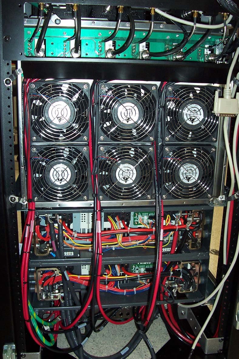
PURMCSERIESHP10
Mar 26, 2007MC Series High Power
Equipment Class
TNB - Licensed Non-Broadcast Station Transmitter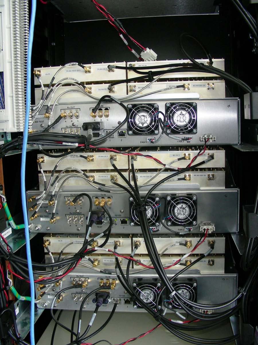
PURMCSERIESMP
Sep 30, 2006MC Series Mid Power
Equipment Class
TNB - Licensed Non-Broadcast Station Transmitter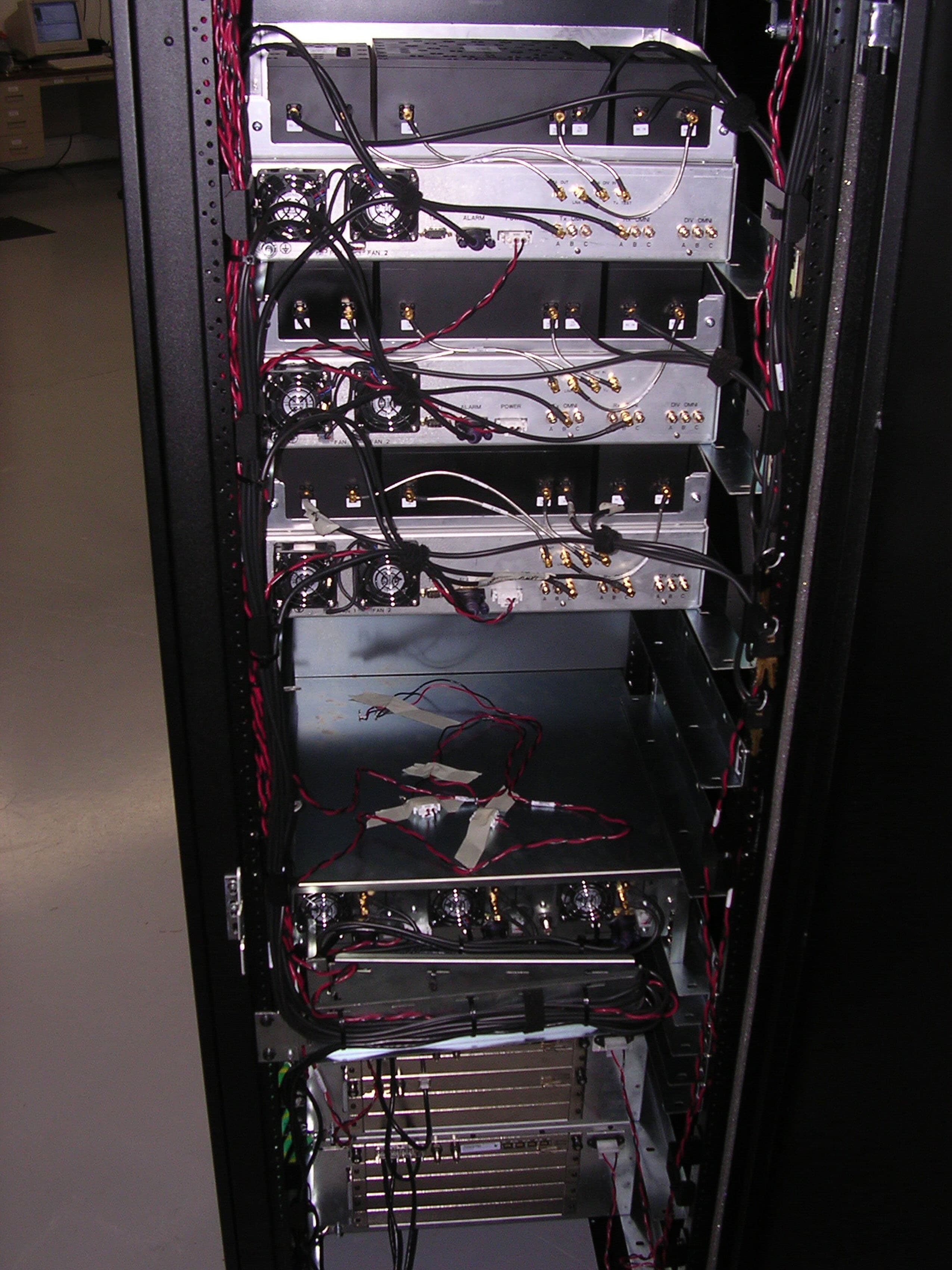
PURMCRB10
Apr 16, 2006MCRB
Equipment Class
TNB - Licensed Non-Broadcast Station Transmitter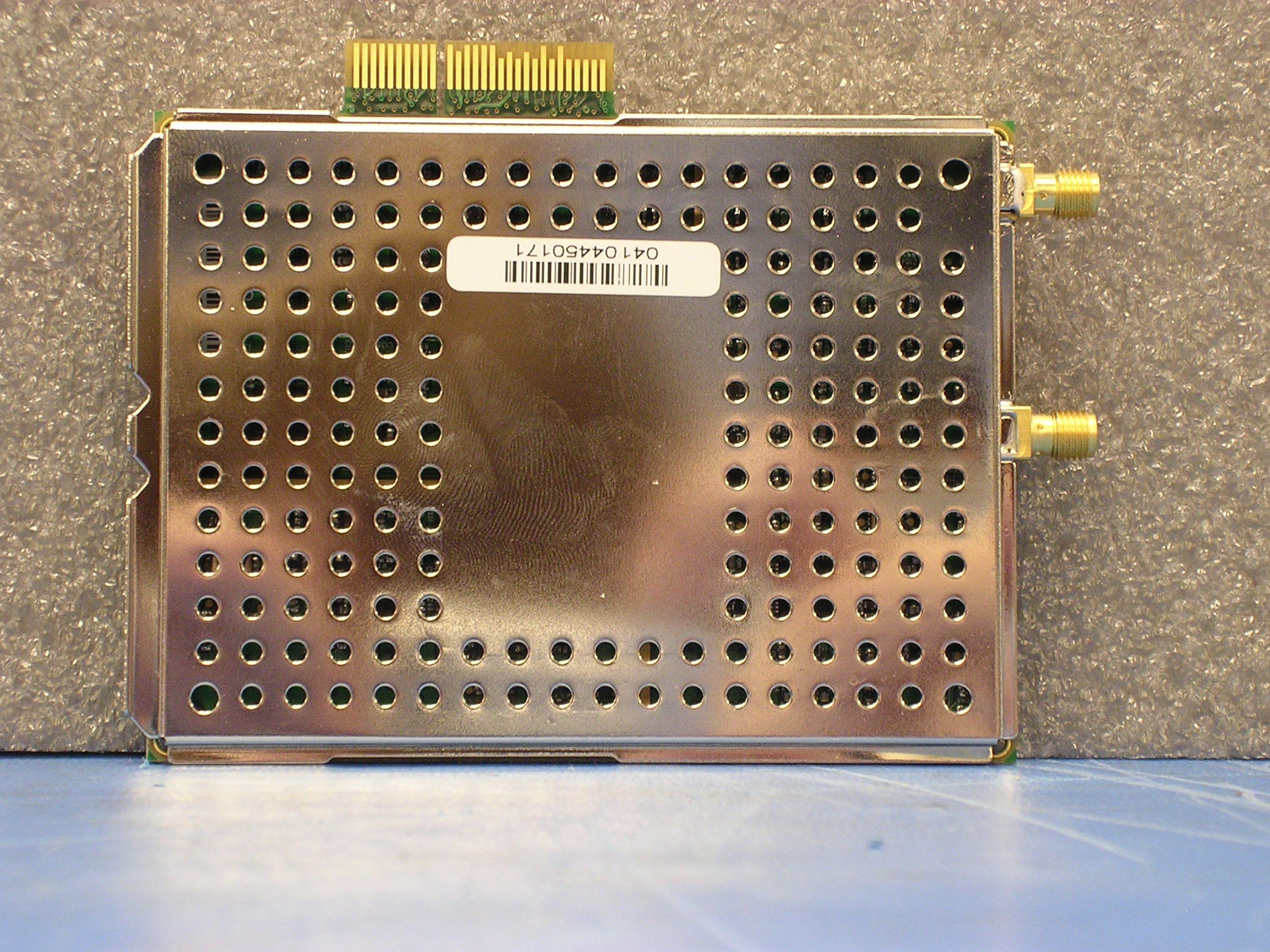
PURBSERIESGSMNA10
May 03, 2005B-Series GSM 1.0
Equipment Class
PCB - PCS Licensed Transmitter
PURMCSERIES10
Mar 14, 2005MC-15
Equipment Class
TNB - Licensed Non-Broadcast Station Transmitter