PURMCSERIESHP10MC Series High Power
RadioFrame Networks, Inc
Click to zoom
Application Details
- Equipment Class
- TNB - Licensed Non-Broadcast Station Transmitter
- Date of Grant
- Mar 26, 2007
- Application Purpose
- Original Equipment
- Date of Application
- Mar 26, 2007
- Equipment Note
- MC Series High Power
- Frequency Range
- 935.01870000 - 939.98120000
- Company
- RadioFrame Networks, Inc
- Country
- United States
Documents & Files
Document Text
Text extracted from the exhibit documents filed with the FCC. Open a document above to read the original.
Users Manual
CONFIDENTIAL AND PROPRIETARY RadioFrame Networks, Inc. RadioFrame Networks MC-Series High-Power System Implementation Guide The information contained in this document is subject to, and designated as confidential Information of RadioFrame Networks in accordance with, the Mutual Nondisclosure Agreement dated as of October 9, 2002, as amended on September 9, 2004, by and between Nextel Communications, Inc. (Sprint Nextel) and RadioFrame Networks, Inc. November 3, 2006 998--01 Rev X1 Revision History MC-Series High-Power System 998--01 Rev X1 Service Information This equipment complies with part 15 of the FCC Rules. Operation is subject to the two following conditions: This device may not cause harmful interference, and this device must accept any interference received, including interference that may cause undesired operation. This equipment has been tested and found to comply with the limits pursuant to part 90.691 of the FCC Rules. These limits are designed to provide reasonable protection against harmful interference when the equipment is operated in a commercial environment. Copyrights and Trademarks RadioFrame Networks is a trademark or service mark, and RadioFrame, RadioBlade and the RadioFrame Networks logo are registered trademarks of RadioFrame Networks, Inc. You may not use these or any other RadioFrame Networks trademarks or service marks without the written permission of RadioFrame Networks, Inc. All third-party product names and services are the property of their respective owners. Throughout this publication, the terms RadioFrame Networks, RadioFrame and RFN signify RadioFrame Networks, Inc. MC-Series High-Power System Implementation Guide © Copyright 2006 RadioFrame Networks, Inc. All Rights Reserved. No part may be reproduced, in any media, except as authorized by written permission of RadioFrame Networks, Inc. ii CONFIDENTIAL AND PROPRIETARY RadioFrame Networks, Inc. Revision History Date Rev Notes November 3, 2006 X1 Preliminary Submit comments and corrections to: RadioFrame Networks, Inc. Technical Information Department 9461 Willows Road NE, Suite 100 Redmond, WA 98052 Tel.: +1 425 278 2780 Fax: +1 425 278 2781 http://www.radioframenetworks.com E-mail [email protected] This document is posted as a .pdf file on the RadioFrame Networks web site at: http://www.radioframenetworks.com/partners MC-Series High-Power System Revision History 998--01 Rev X1 RadioFrame Networks, Inc. CONFIDENTIAL AND PROPRIETARY iii Table of Contents 1 Introduction ......................................................................................................................................... 10 1.1 References .................................................................................................................................. 10 1.2 General Safety Information ......................................................................................................... 10 1.2.1 Static Sensitive Precautions ............................................................................................... 10 1.2.2 Safety Warnings.................................................................................................................. 11 1.2.2.1 Safety Warnings per Rack Mount Instructions ........................................................... 11 1.2.3 Recommendations .............................................................................................................. 12 1.3 Repair and Technical Support ..................................................................................................... 12 1.3.1 Technical Support ...............................................................................................................13 1.3.2 Field Replaceable Unit (FRU) Policy .................................................................................. 13 2 System Definition................................................................................................................................ 14 2.1 MC-Series High Power System Configuration ............................................................................ 16 2.2 RadioFrame Networks Hardware ................................................................................................ 19 2.2.1 Air/BTS Interface Chassis (ABIC)....................................................................................... 19 2.2.1.1 BIC CRIC.................................................................................................................... 20 2.2.1.2 BPC ............................................................................................................................20 2.2.1.3 ERTM ......................................................................................................................... 20 2.2.1.4 CRTC ......................................................................................................................... 20 2.2.1.5 BIC Ports .................................................................................................................... 21 2.2.1.6 BIC Indicators............................................................................................................. 21 2.2.2 Airlink Interface Chassis (AIC) ............................................................................................ 22 2.2.2.1 AIC CRIC.................................................................................................................... 22 2.2.2.2 BPC+SPAM................................................................................................................ 22 2.2.2.3 ERTM ......................................................................................................................... 22 2.2.3 RadioBlade Shelf (RBS) ..................................................................................................... 22 2.2.3.1 RBS Ports............................................................................…
Text truncated - open the document above for the full version.
Cover Letter(s)
Northwest EMC TCB Compliance Opinion Rev. 9/15/03 RAFN0073 Information about the Applicant Company Name Radioframe Networks, Inc. Grantee Steve Peters Address 9461 Willows Road NE, Suite 100 City, State, Zip Redmond, WA 98052 Job Number RAFN0073 Model MC-Series iDEN Microcell High Power FCC ID PURMCSERIESHP10 Agent none Approval Type Original Equipment Class TNB Licensed Non-Broadcast Base Station Transmitter Rule Part 90.691 Overview This application is for the certification of the MC Series High Power Base Station PURMCSERIESHP10. The base station operates in the 850 and 900 MHz ESMR Cellular services per 47 Cfr Part 90 Subpart I. Recommendation All items have been resolved and completed to my satisfaction; therefore I recommend this application for approval. Signature Dave Tolman, TCB Committee 3/22/2007
External Photos
1 PA SwitchesPA Power Supplies Power Amplifiers Front View 2 Power Amplifier Shelf Front View Status Monitor LED’s 3 Tx Input/Output PA Chassis Back PA Power Supplies Rear View 4 PA Connectors PA Shelf Cooling Fans PA Shelf 5 PA Top Vertical View Cooling Fins RFConnector 6 PA Rear View PA Connector RF ConnectorSerial number 7 PA Top Horizontal View Cooling Fins Handle 8 PA Front View Air Cooling Opening Status LED’s
Internal Photos
MCRB PCB Front MCRB PCB Back MCRB Front MCRB Back MCRB Connectors
Parts List/Tune Up Info
11/6/2006 9:21:05 AM RadioFrame Networks Proprietary Created by: Andrea Bernard 101-0581-01 BOM EXPLOSION REPORT SUB ASY, POWER DISTRIBUTION UNIT (PDU), HIGH POWER Part Number Part Description Part Revision LevelPart TypeItem NumberRevItem DescriptionFind Num QtyRef DesBOM Notes 01-Ops/RFN Mfg 101-0581-01SUB ASY, POWER DISTRIBUTION UNIT (PDU), HIGH POWER .11-Ops/RFN Mfg 110-1262-R00ATERMINAL BLOCK, POWER FEED THRU, 6-POLE, LEAD FREE 01 .15-Misc Part510-1277-R01ACHASSIS, PDU, HIGH POWER 01 .15-Misc Part510-1278-R01ACOVER, PDU, HIGH POWER01 .15-Misc Part510-1279-R01ABUSS BAR, LINE, PDU, HIGH POWER 01 .15-Misc Part510-1280-R01ABUSS BAR, RETURN, PDU, HIGH POWER 01 .15-Misc Part510-1281-R02BUSS BAR, 2-POLE CB, LEFT, PDU, HIGH POWER 01 .15-Misc Part510-1281-R12BUSS BAR, 2-POLE CB, RIGHT, PDU, HIGH POWER 01 .15-Misc Part511-0011-R01ACOVER, TERMINAL BLOCK, POWER FEED THRU, 6-POLE, LEAD FREE 01 .15-Misc Part520-0880-991NUT, K-LOK, 1/4-20024 .15-Misc Part520-0890-99BNUT, NYLON INSERT STOP, #4-40 08 .15-Misc Part527-0002-03ACIRCUIT BREAKER, HP PDU, 3A 05 .15-Misc Part527-0002-10ACIRCUIT BREAKER, HP PDU, 10A 03 .15-Misc Part527-0003-01ACIRCUIT BREAKER, 2-POLE, 125A 02 .15-Misc Part533-0204-03SCR, #6-32 X 1/4, PPH, INT SEMS, BLK OX 032 .18- Connector/S ocket 820-0632-01AASY, CABLE, POWER, PDU, HP 08 .18- Connector/S ocket 820-0633-01AASY, CABLE, SENSE, PDU, HP 01 .18- Connector/S ocket 820-0634-01AASY, CABLE, CB, PDU, HP09 .1Document910-0581-01SUB LEVEL ASY DWG, PDU, HIGH POWER 00 Page 1 of 1 11/8/2006 12:00:06 PM RadioFrame Networks Proprietary Created by: Andrea Bernard 101-1017-01 BOM EXPLOSION REPORT SUB ASY, CABINET, MC-SERIES, HP Part Number Part Description Part Revision LevelPart TypeItem NumberRevItem DescriptionFind Num QtyRef DesBOM Notes 01-Ops/RFN Mfg 101-1017-01SUB ASY, CABINET, MC- SERIES, HP .11-Ops/RFN Mfg 110-1051-01ACABINET, MC-SERIES, HIGH POWER 01 .15-Misc Part510-1232-02DBRACKET, SHELF SUPPORT020 .15-Misc Part510-1296-R02BULKHEAD, CABINET TOP, HIGH POWER 01 .15-Misc Part520-0590-992SCREW, #10-32 X 1/2, ZOS, PPH, EXT SEMS 014 .15-Misc Part520-0880-991NUT, K-LOK, 1/4-2004 .15-Misc Part521-0701-001CABLE TIE, HOOK AND LOOP 8" X .5" BLACK 014 .15-Misc Part539-0001-002SCREW, RACK 10-32 X 5/8 BLK 044 .15-Misc Part546-0003-001CAP, N-TYPE PLASTIC RED06 .18- Connector/S ocket 802-0170-051CONN, ADAPTER, TYPE-N BULKHEAD J/J PRESSURIZED 06 .18- Connector/S ocket 820-0609-00CASY, CABLE, GROUND, 6AWG GRN-YLW, AL W/RING TERMINALS, 6" 011 .18- Connector/S ocket 820-0609-10CASY, CABLE, GROUND, 6AWG GRN-YLW, AL W/RING TERMINALS, 12" 01 .18- Connector/S ocket 820-0625-10DASY, CABLE, GND, 6AWG, DUAL LUG, 12" 01 .18- Connector/S ocket 820-0625-20DASY, CABLE, GND, 6AWG, DUAL LUG, 24" 01 ..28- Connector/S ocket 807-0016-05BLUG, 6AWG, 2-HOLE, STANDARD BARREL W/WINDOW, COPPER, STRAIGHT 02 ..28- Connector/S ocket 825-0547-001CABLE, 6AWG, 600 VOLT, 133/27, UL 1283/1232 TEMP=105°C, CSA TEW 01 .1Document910-1017-01SUB-LEVEL ASY DWG, CABINET, MC-SERIES, HIGH POWER 00 Page 1 of 1 11/8/2006 3:53:40 PM RadioFrame Networks Proprietary Created by: Andrea Bernard 101-1015-01 BOM EXPLOSION REPORT SUB ASY, BANDSPLITTER, MC-SERIES, HIGH POWER Part Number Part Description Part Revision LevelPart TypeItem NumberRevItem DescriptionFind Num QtyRef DesBOM Notes 01-Ops/RFN Mfg 101-1015-01SUB ASY, BANDSPLITTER, MC-SERIES, HIGH POWER .15-Misc Part500-0309-05AATTENUATOR, BANDSPLITTER, 800-900MHZ, MC-SERIES HI PWR PRE-PA 03 ..2Document907-0309CSSRD, MC SERIES HIGH POWER PRE-PA BAND SPLITTER/ATTENUATOR 00 .15-Misc Part510-0002-01ASHROUD, PA SHELF, MC- SERIES, HP 01 .15-Misc Part510-0003-01ACOVER, SHROUD, PA SHELF, MC-SERIES, HP 01 .15-Misc Part520-0002-01AFASTENER, PANEL, PLUNGER, 3/16" 04 .15-Misc Part520-0003-01AFASTENER, PANEL, GROMMET, 3/16" 04 .15-Misc Part520-0890-99BNUT, NYLON INSERT STOP, #4-40 06 .1Document910-1015-01SUB-LEVEL ASY DWG, BANDSPLITTER, MC-SERIES, HIGH POWER 00 Page 1 of 1 11/6/2006 9:53:18 AM RadioFrame Networks Proprietary Created by: Andrea Bernard 101-1012-01 BOM EXPLOSION REPORT SUB ASY, TX FILTER SHELF, MC-SERIES, HIGH POWER Part Number Part Description Part Revision LevelPart TypeItem NumberRevItem DescriptionFind Num QtyRef DesBOM Notes 01-Ops/RFN Mfg 101-1012-01SUB ASY, TX FILTER SHELF, MC-SERIES, HIGH POWER .15-Misc Part510-1290-R01CHASSIS, TX FILTERS01 .15-Misc Part510-1298-12BRKT, TX FILTER CHASSIS01 .15-Misc Part514-0001-991TERMINATOR, N-M W/CHAIN 2W 6GHZ, 18DB MAX VSWR @ 6GHZ 03 .15-Misc Part520-0520-991SCREW, #8-32 X 3/8, ZOS, PPH, EXT SEMS 04 .15-Misc Part520-0590-992SCREW, #10-32 X 1/2, ZOS, PPH, EXT SEMS 04 .15-Misc Part521-0520-99CHANDLE, ALUMINUM, 5" CTC02 .15-Misc Part530-0306-721SCR, #8-32 X 3/8, FHP, ST ZN, UN 018 .15-Misc Part533-0205-031SCR, #6-32 X 5/16, BLK OX, INT SEMS 03 .11-Ops/RFN Mfg 820-0605-31HASY, CABLE SMA ST/BH, 15.5" 03 .18- Connector/S ocket 820-0635-10AASY, CABLE, TYPE N BH/SMA ST, INSULATED, 22.0" 03 .1Document910-1012-01SUB-LEVEL ASY DWG, TX FILTER SHELF, HIGH POWER 00 Page 1 of 1 11/8/2006 4:12:15 PM RadioFrame Networks Proprietary Created by: Andrea Bernard 101-1011-01 BOM EXPLOSION REPORT SUB ASY, RADIOBLADE SHELF (RBS), MC-SERIES, HIGH POWER Part Number Part Description Part Revision LevelPart TypeItem NumberRevItem DescriptionFind Num QtyRef DesBOM Notes 01-Ops/RFN Mfg 101-1011-01SUB ASY, RADIOBLADE SHELF (RBS), MC-SERIES, HIGH POWER .11-Ops/RFN Mfg 102-0011-04CASY, FAN 60MM X 25MM 12VDC 37 CFM 3 WIRE 03 ..25-Misc Part518-0002-001FAN, 60MM X 25MM 12VDC 37 CFM 3 WIRE 01 ..25-Misc Part543-0001-001TUBING, HEAT SHRINK, 1/4" EXPANDED, 1/8" SHRUNKEN, PVC 00 ..28- Connector/S ocket 806-0601-051CONN., 3 CKT RECEPTACLE HOUSING 01 ..28- Connector/S ocket 806-0609-051CONN., CONTACT, #18-24, 4.20MM, FEMALE, CRIMP 03 .11-Ops/RFN Mfg 123-0680-R02ALABEL, BLANK, 2.00 X 0.500, GLOSSY WHITE, POLYESTER, LEAD FREE 02 .15-Misc Part508-0631-991FAN, FINGER GUARD, METAL, 60MM 03 .15-Misc Part510-0760-01ABRACKET, RIB SUPPORT, BACKPLANE, CU 01 .15-Misc Part510-1222-02CCOVER, CHASSIS, RB…
Text truncated - open the document above for the full version.
Parts List/Tune Up Info
User Manual 6.1.4.1 defaultTxPower Note: Refer to release notes for range information. This is the average output power of the PA, measured at the RF connector of the BR. For the MC-Series High-Power system, this parameter can be used to adjust the output power of the system. The gain at the shelf is fixed and cannot be altered as was the case with the 800-only RF Shelf. The MC-Series High-Power system has a different range of output levels than a standard Motorola EBTS, and as such, these values will map to a different set of actual Tx output power levels. (The correspondence is shown in Table 16 in section 2.5.8.3 .) The nominal maximum Tx power at the top of the rack with a maximum variation of ± 2 dB is +29 dBm. The dynamic range is 11 dB.
Test Report
Radioframe Networks, Inc. MC-Series iDEN Microcell High Power March 6, 2007 Report No. RAFN0073 Report Prepared By www.nwemc.com 1-888-EMI-CERT © 2006 Northwest EMC, Inc 22975 NW Evergreen Parkway Suite 400 Hillsboro, Oregon 97124 Certificate of Test Issue Date: March 6, 2007 Radioframe Networks, Inc. Model: MC-Series iDEN Microcell High Power Emissions Test Description Specification Test Method Pass Fail Radiated Emissions FCC 15.109:2006 ANSI C63.4:2003 Conducted Emissions FCC 15.107:2006 ANSI C63.4:2003 Frequency Stability FCC 90I:2005 ANSI/TIA/EIA-603-B:2002 Field Strength of Spurious Radiation FCC 90I:2005 ANSI/TIA/EIA-603-B:2002 Emission Mask FCC 90I:2005 ANSI/TIA/EIA-603-B:2002 Output Power FCC 90I:2005 ANSI/TIA/EIA-603-B:2002 Spurious Emissions at Antenna Terminal FCC 90I:2005 ANSI/TIA/EIA-603-B:2002 Modifications made to the product See the Modifications section of this report Test Facility The measurement facility used to collect the data is located at: Northwest EMC, Inc. 22975 NW Evergreen Parkway, Suite 400; Hillsboro, OR 97124 Phone: (503) 844-4066 Fax: 844-3826 This site has been fully described in a report filed with and accepted by the FCC (Federal Communications Commission) and Industry Canada. Approved By: Donald Facteau, IS Manager This report must not be used to claim product certification, approval, or endorsement by NVLAP, NIST, or any agency of the federal government of the United States of America. Product compliance is the responsibility of the client, therefore the tests and equipment modes of operation represented in this report were agreed upon by the client, prior to testing. This Report may only be duplicated in its entirety. The results of this test pertain only to the sample(s) tested, the specific description is noted in each of the individual sections of the test report supporting this certificate of test. Northwest EMC Revision History Revision 05/05/03 Revision Number Description Date Page Number 00 None Northwest EMC Accreditations and Authorizations Revision 03/18/05 FCC: Accredited by NVLAP for performance of FCC radio, digital, and ISM device testing. Our Open Area Test Sites, certification chambers, and conducted measurement facilities have been fully described in reports filed with the FCC and accepted by the FCC in letters maintained in our files. Northwest EMC has been accredited by ANSI to ISO / IEC Guide 65 as a product certifier. We have been designated by the FCC as a Telecommunications Certification Body (TCB). This allows Northwest EMC to certify transmitters to FCC specifications in accordance with 47 CFR 2.960 and 2.962. NVLAP: Northwest EMC, Inc. is accredited under the United States Department of Commerce, National Institute of Standards and Technology, and National Voluntary Laboratory Accreditation Program for satisfactory compliance with the requirements of ISO/IEC 17025 for Testing Laboratories. The NVLAP accreditation encompasses Electromagnetic Compatibility Testing in accordance with the European Union EMC Directive 89/336/EEC, ANSI C63.4, MIL- STD 461E, DO-160D and SAE J1113. Additionally, Northwest EMC is accredited by NVLAP to perform radio testing in accordance with the European Union R&TTE Directive 1999/5/EEC, the requirements of FCC, and the RSS radio standards for Industry Canada. NVLAP LAB CODE 200629-0 NVLAP LAB CODE 200630-0 NVLAP LAB CODE 200676-0 Industry Canada: Accredited by NVLAP for performance of Industry Canada RSS and ICES testing. Our Open Area Test Sites and certification chambers comply with RSS 212, Issue 1 (Provisional) and have been filed with Industry Canada and accepted. Northwest EMC has been accredited by ANSI to ISO / IEC Guide 65 as a product certifier. We have been designated by NIST and recognized by Industry Canada as a Certification Body (CB) per the APEC Mutual Recognition Arrangement (MRA). This allows Northwest EMC to certify transmitters to Industry Canada technical requirements. CAB: Designated by NIST and validated by the European Commission as a Conformity Assessment Body (CAB) to conduct tests and approve products to the EMC directive and transmitters to the R&TTE directive, as described in the U.S. - EU Mutual Recognition Agreement. TÜV Product Service: Included in TUV Product Service Group's Listing of Recognized Laboratories. It qualifies in connection with the TUV Certification after Recognition of Agent's Testing Program for the product categories and/or standards shown in TUV's current Listing of CARAT Laboratories, available from TUV. A certificate was issued to represent that this laboratory continues to meet TUV's CARAT Program requirements. Certificate No. USA0401C. TÜV Rheinland: Authorized to carryout EMC tests by order and under supervision of TÜV Rheinland. This authorization is based on "Conditions for EMC-Subcontractors" of November 1992. Northwest EMC Accreditations and Authorizations Revision 03/18/05 NEMKO: Assessed and accredited by NEMKO (Norwegian testing and certification body) for European emissions and immunity testing. As a result of NEMKO's laboratory assessment, they will accept test results from Northwest EMC, Inc. for product certification (Authorization No. ELA 119). Australia/New Zealand: The National Association of Testing Authorities (NATA), Australia has been appointed by the ACA as an accreditation body to accredit test laboratories and competent bodies for EMC standards. Accredited test reports or assessments by competent bodies must carry the NATA logo. Test reports made by an overseas laboratory that has been accredited for the relevant standards by an overseas accreditation body that has a Mutual Recognition Agreement (MRA) with NATA are also accepted as technical grounds for product conformity. The report should be endorsed with the respective logo of the accreditation body (NVLAP). VCCI: Accepted as an Associate Member to the VCCI, Acceptance No. 564. Conducted and radiated measurement facilities have been registered in accordance with Regula…
Text truncated - open the document above for the full version.
Test Setup Photos
NORTHWEST EMC OUTPUT POWER XMit 2006.08.25 NORTHWEST EMC OUTPUT POWER XMit 2006.08.25 NORTHWEST EMC OUTPUT POWER XMit 2006.11.13 NORTHWEST EMC OUTPUT POWER XMit 2006.11.13 NORTHWEST EMC Radiated Emissions PSA 2006.10.30 NORTHWEST EMC Radiated Emissions PSA 2006.10.30 NORTHWEST EMC Radiated Emissions PSA 2006.10.30 NORTHWEST EMC Conducted Emissions PSA 2006.10.30 NORTHWEST EMC Conducted Emissions PSA 2006.10.30 NORTHWEST EMC SPURIOUS EMISSIONS AT ANTENNA TERMINALS XMit 2006.08.25 NORTHWEST EMC Field Strength of Spurious Radiation PSA 2006.10.30 NORTHWEST EMC Field Strength of Spurious Radiation PSA 2006.10.30 NORTHWEST EMC EMISSION MASK XMit 2006.11.13 NORTHWEST EMC EMISSION MASK XMit 2006.11.13 NORTHWEST EMC SPURIOUS EMISSIONS AT ANTENNA TERMINALS XMit 2006.11.13 NORTHWEST EMC SPURIOUS EMISSIONS AT ANTENNA TERMINALS XMit 2006.11.13
Contact Information
Applicant
Dean Busch(Sr. Compliance Engineer)
Test Firm
Northwest EMC, Inc.Greg Kiemel
Technical Specifications
| # | Rule Parts | Frequency Range | Power Output | Emission | Tolerance |
|---|---|---|---|---|---|
| 2 | 9 | 935.0187 MHz - 939.9812 MHz | 8.32 W | 25K0D7W | 0.05 ppm |
Other Applications from RadioFrame Networks, Inc
PURSSERIESGSMNA02
Apr 23, 2007S -BTS GSM Base Station
Equipment Class
PCB - PCS Licensed Transmitter
PURMCSERIESMP
Sep 30, 2006MC Series Mid Power
Equipment Class
TNB - Licensed Non-Broadcast Station Transmitter
PURMCRB10
Apr 16, 2006MCRB
Equipment Class
TNB - Licensed Non-Broadcast Station Transmitter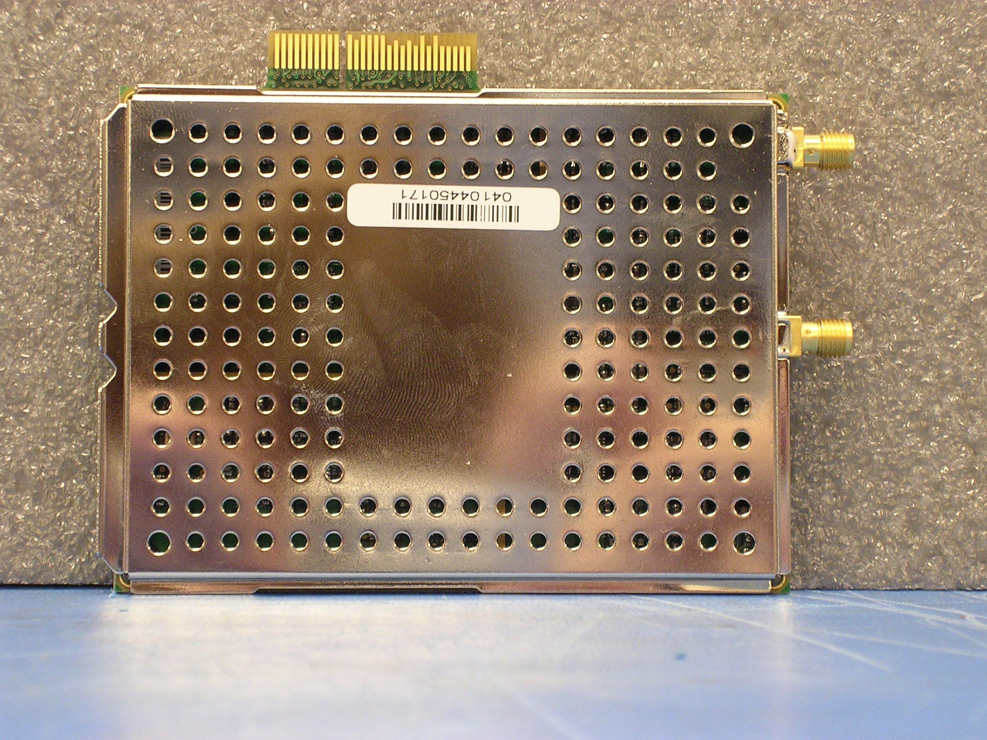
PURBSERIESGSMNA10
May 03, 2005B-Series GSM 1.0
Equipment Class
PCB - PCS Licensed Transmitter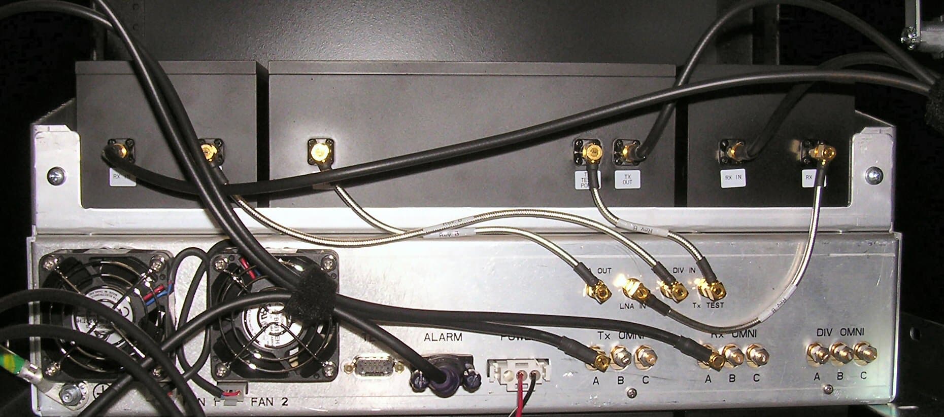
PURMCSERIES10
Mar 14, 2005MC-15
Equipment Class
TNB - Licensed Non-Broadcast Station Transmitter