PVCGTP205Audio Video Transmitter
Grantec Electronic Corp.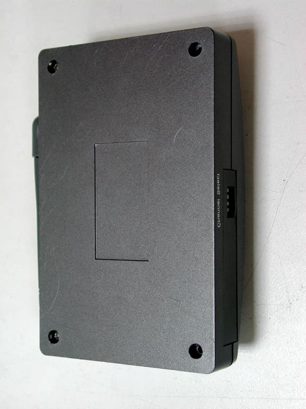
Click to zoom
Application Details
- Equipment Class
- DXX - Part 15 Low Power Communication Device Transmitter
- Date of Grant
- Dec 18, 2001
- Application Purpose
- Original Equipment
- Date of Application
- Dec 18, 2001
- Equipment Note
- Audio Video Transmitter
- Frequency Range
- 2414.00000000 - 2468.00000000
- Company
- Grantec Electronic Corp.
- Country
- Taiwan
Documents & Files
Document Text
Text extracted from the exhibit documents filed with the FCC. Open a document above to read the original.
Users Manual
1 CHAPTER 1 INTRODUCTION 1.1 Introduction Thank you for purchasing the GRAND RF AMAZING EX, The GRAND RF AMAZING EX is a Wireless Audio & Video transmitter and receiver that delivers amazingly clear audio and video close to 100 meters in open area (30 meters through walls or floors), Four selectable transmitting channels allow transmitter to receiver operation in the same area. 1.2 Features l ISM Band: 2400MHz~2483MHz l Full Range: EIA, CCIR, NTSC, PAL l Four selectable channel Transmitter & Receiver l Built-in PLL circuit l Remote Entertainment, Attendance, Surveillance Market: DIY, SOHO, Safety, Security 2 1.3 Applications a. Business l Observe warehouse, sales floor, and doors, without expensive and inflexible wiring l Show computer images on remote TV’s for training and presentation when used with PC to TV converters like our Grand Ultimate 2000 EX or Grand Magic View EX. l Deliver your message to multiple TV’s in tradeshow’s without wires, even to multiple booths b. Entertainment l Listen to music all over the house and even out on the patio or pool area from the central player using Grand RF AMAZING EX and powered speakers. l Enjoy satellite TV, rented tapes and DVD’s in the room of the house without expensive wiring c. Safety l See who is outside your door on TV using a small camera and GRAND RF AMAZING EX and your regular TV. l Monitor your baby, your children, the swimming pool, or elderly, ill or disabled in your family using your camcorder or miniature camera. l Observe your home or office on your Computer monitor with used with a TV to Computer Converter, like our Grand Joy Mate. 3 1.4 Specifications l ISM Band: 2400Mhz ~2483Mhz Audio/Video on four selectable channels l Antenna Mode: Dipole l Demodulation Method: FM l Frequency Generating: P. L. L. l Audio Response: 20~20KHz l Video Output : 1Vpp/ 75 ohm Composite Video l RF Output Power: Follow the regulation. l Dimension: 12.5(L) X 8 (W) X 3.3(H) cm. 1.5 Transmitter l DC power IN (Adaptor) : DC 6V, 800mA l Frequency Stability: 100KHz l Current Consumption: under 130mA (Typical) l Audio Input Level: 1 Vrms (Typical) l Antenna Port: 50 Ohm PCB Track. 1.6 Receiver l DC power IN (Adaptor) : DC 6V, 800mA l Frequency : 2400MHz ~2483MHz. l Current Consumption: under 200mA. (Typical) l RX Sensitivity: -80dbm (Minimum) l Antenna Port: 50 Ohm PCB Track 4 1.7 Package Contents This package contains the following items: l User’s Manual For Transmitter l GRAND RF AMAZING EX Tx l Video & Stereo Audio cable l Power Adapter For Receiver l GRAND RF AMAZING EX Rx l Video & Stereo Audio cable l Power Adapter Video & Stereo Audio cable 5 1.8 Connectors of Grand RF Amazing EX l AUDIO – L INPUT & AUDIO – R INPUT: Connect RF AMAZING EX Tx to AUDIO OUTPUT of your VCR, CCD Camera etc. l VIDEO INPUT: Connects RF AMAZING EX Tx to VIDEO OUTPUT of your VCR, Camcorder, CCD Camera etc. l DC IN: Power connector, connects with the supplied power adapter. l Channel Select: Selects channel that you want to send. 6 l AUDIO – L OUTPUT & AUDIO – R OUTPUT: Connect RF AMAZING EX Rx to the AUDIO INPUT of TV or a powered Speaker l VIDEO OUTPUT: Connects RF AMAZING EX Tx to VIDEO INPUT of your VCR, Camcorder, CCD Camera etc. l DC IN: Power connector, connects with the supplied power adapter. l Channel Select: Selects channel that you want to view. 7 CHAPTER 2 Hardware Installation 2.1 Introduction Using absolutely no wires, Grand RF AMAZING EX can send audio or video signals from virtually any sound or picture source to any TV or powered speakers using the same connectors as your other electronics. To enjoy wireless video and audio, just connect the transmitter to whatever picture or sound source you want to view or hear at another location, and then connect the receiver to the TV or powered speakers in that other location. Then plug-in the Adapter (DC 6V, 800mA) on both the transmitter and receiver and you are ready to go wireless. 2.2 Installation and setting up the channels 1. Grand RF AMAZING EX Tx (Wireless Transmitter) : set up the channel (4 selectable channels), link the Transmitter and picture or/and sound source with an AV wire, and plug-in the adapter (DC 6V, 800mA ) 2. Grand RF AMAZING EX Rx (Wireless Receiver) : Link the Receiver and TV with an AV Wire, please adjust the Dip-Switch at the back of the Receiver. Setting up the channel that you wish to view: place the channel dip-switch in the “down” position. Setting up channels that you wish to disable : place the channel dip-switch in the “up” position i.e. If the CH1 dip - switch is in the down position, means CH1 will be selected. Use the same procedure to select the other channels 8 3. The users can use four wireless Transmitters ( Grand RF AMAZING EX Tx) on 4 different channels. The Wireless Receiver (Grand RF AMAZING EX Rx) can receive up to 4 difference frequency signals. 9 CHAPTER 3 Trouble Shooting Please check the following chart for a possible solution of problem. If you are experiencing, a minor adjustment may eliminate the problem. SymptomsPossible Solutions No picture or sound1. Be sure power adapter is plugged in. 2. Be sure AV cable is connected. Interference Noisy picture or audio1. Adjust receiver antenna orientation. 2. Adjust transmitter antenna orientation. 3. Select a different channel with the jumper on transmitter and adjust the Dip-Switch at the back of the Receiver, so that the channels match. 10 When you need RMA or advanced technique service, please fill this form as detail as possible and FAX to your dealer. Product S/N: Name: TEL No.:FAX No.: E-mail address: Full Address: Hardware condition: Mainboard chipset: Mainboard CPU:CPU clock: MHz Main memory: MBCache memory: KB VGA card:Display memory: MB Sound card:Hard Disk: MB Other add-on cards: Monitor:Horizontal Freq.: KHz to KHz Vertical Freq.: Hz to Hz Problem description:
Block Diagram
1 GTP205 Transismitter / Receiver Block Diagram RX1 RF 2.4GHz Receiver module Channel select Antenna Audio-R Out Audio-L Out DC IN JACK Video Out OSC with LED indicator TX1 RF 2.4GHz Transmitter module Channel select Antenna Audio-R IN Audio-L IN DC IN JACK Video IN OSC with LED indicator Regulator Regulator
Cover Letter(s)
American Telecommunications Certification Body Inc. 6731 Whittier Ave, McLean, VA 22101 December 18, 2001 RE: Grandtec Electronic Corporation FCC ID: PVCGTP205 I have a few comments on this Application. 1.) Please supply an FRN with this Applicant. Beginning December 3, all entities doing business with the FCC must be registered and have their own unique FRN. Please go to the following link to obtain this number: https://gullfoss2.fcc.gov/cores/CoresHome.html 2.) Please note that Internal Photos cannot be held Confidential. Please correct. 3.) FYI: Please note you may wish to include the Parts List and Block Diagram in your Confidentiality request. Thank you. William H. Graff President and Examining Engineer mailto: [email protected] The items indicated above must be submitted before processing can continue on the above referenced application. Failure to provide the requested information may result in application termination. Correspondence should be considered part of the permanent submission and may be viewed from the Internet after a Grant of Equipment Authorization is issued. Please do not respond to this correspondence using the email reply button. In order for your response to be processed expeditiously, you must submit your documents through the AmericanTCB.com website. Also, please note that partial responses increase processing time and should not be submitted. Any questions about the content of this correspondence should be directed to the sender.
ID Label/Location Info
LABEL Format: This device complies with Part 15 of the FCC Rules Operation is subject to the following two conditions: (1) This device may not cause harmful interference, and (2) This device must accept any interference received, including interference that may cause undesired operation Model No.:GTP-205 FCC ID:PVCGTP205 LABEL Size: 45 x 24 mm LABEL Position:
Test Report
Test Report ------------------------------------------------------------------------------- 1/33 Report No.: GA215372, FCC Part 15 Class B Training Research Co., Ltd., TEL:886-2-26935155, Fax:886-2-26934440 MEASUREMENT REPORT of Wireless Audio Video Transmitter Applicant: GRANDTEC ELECTRONIC CORP. Product Name:RF AMAZING EX Model No.:GTP-205, RF AMAZING EX, RF-1000 FCC ID:PVCGTP205 EUT:Audio/Video Transmitter Report No.:GA215372 Test by : Training Research Co., Ltd. TEL : 886-2-26935155 FAX : 886-2-26934440 2, Lane 194, Huan-Ho Street, Hsichih, Taipei Hsien 221, Taiwan, R.O.C. Test Report ------------------------------------------------------------------------------- 3/33 Report No.: GA215372, FCC Part 15 Class B Training Research Co., Ltd., TEL:886-2-26935155, Fax:886-2-26934440 CONTENTS I. GENERAL 1.1 Introduction ................................................................................................................... 5 1.2 Description of EUT ....................................................................................................... 5 1.3 Description of Support Equipment ................................................................................. 6 1.4 Configuration of System Under Test ............................................................................... 7 1.5 Test Procedure .............................................................................................................. 9 1.6 Location of the Test Site ................................................................................................ 9 1.7 General Test Condition .................................................................................................. 9 II. Conducted Emissions Measurements 2.1 Test Condition & Setup ............................................................................................... 10 2.2 List of Test Instruments ................................................................................................ 10 2.3 Test Configuration ....................................................................................................... 11 2.4 Test Result of Conducted Emissions ............................................................................. 13 III. Radiated Emissions Measurements 3.1 Test Condition & Setup ............................................................................................... 16 3.2 List of Test Instruments ................................................................................................ 17 3.3 Test Instruments Configuration ..................................................................................... 18 3.4 Test Result of Radiated Emissions ................................................................................ 20 3.5 Test Result of Spurious Radiated Emissions .................................................................. 21 . Verify Frequencies and Channels................................................................................... 28 Appendix A 29 Appendix B 31 Test Report ------------------------------------------------------------------------------- 4/33 Report No.: GA215372, FCC Part 15 Class B Training Research Co., Ltd., TEL:886-2-26935155, Fax:886-2-26934440 TABLES Table 1Power Line Conducted Emissions [Channel 1]........................................................................................................ 13 Table 2Power Line Conducted Emissions [Channel 3]........................................................................................................ 14 Table 3Power Line Conducted Emissions [Channel 4]........................................................................................................ 15 Table 4Open Field Radiated Emissions [Channel 1, Horizontal, 30MHz1GHz]............................................................ 21 Table 5Open Field Radiated Emissions [Channel 1, Horizontal, 1GHz24GHz] ........................................................... 22 Table 6Open Field Radiated Emissions [Channel 1, Vertical, 30MHz1GHz] .............................................................. 23 Table 7Open Field Radiated Emissions [Channel 1, Vertical, 1GHz24GHz] ............................................................... 23 Table 8Open Field Radiated Emissions [Channel 3, Horizontal, 30MHz1GHz]............................................................ 24 Table 9Open Field Radiated Emissions [Channel 3, Horizontal, 1GHz24GHz] ........................................................... 24 Table 10Open Field Radiated Emissions [Channel 3, Vertical, 30MHz1GHz] .............................................................. 25 Table 11Open Field Radiated Emissions [Channel 3, Vertical, 1GHz24GHz] ............................................................... 25 Table 12Open Field Radiated Emissions [Channel 4, Horizontal, 30MHz1GHz]............................................................ 26 Table 13Open Field Radiated Emissions [Channel 4, Horizontal, 1GHz24GHz] ........................................................... 26 Table 14Open Field Radiated Emissions [Channel 4, Vertical, 30MHz1GHz] .............................................................. 27 Table 15Open Field Radiated Emissions [Channel 4, Vertical, 1GHz24GHz] ............................................................... 27 Test Report ------------------------------------------------------------------------------- 5/33 Report No.: GA215372, FCC Part 15 Class B Training Research Co., Ltd., TEL:886-2-26935155, Fax:886-2-26934440 I. GENERAL 1.1 Introduction The following measurement report is submitted on behalf of Applicant in support of audio/video transmitter certification in accordance with Part 2 Subpart J and Part 15 Subpart A and C of the Commission's Rules and Regulations. 1.2 Description of EUT Product Name:RF AMAZING EX Model No.:GTP-205, RF AMAZING EX, RF-1000 FCC ID:PVCGTP205 Frequency Range:2414 – 2468 MHz Support Channel:4 Channel…
Text truncated - open the document above for the full version.
Test Setup Photos
Test Report ------------------------------------------------------------------------------- 11/33 Report No.: GA215372, FCC Part 15 Class B Training Research Co., Ltd., TEL:886-2-26935155, Fax:886-2-26934440 2.3 Test configuration Test Report ------------------------------------------------------------------------------- 12/33 Report No.: GA215372, FCC Part 15 Class B Training Research Co., Ltd., TEL:886-2-26935155, Fax:886-2-26934440
Test Setup Photos
Test Report ------------------------------------------------------------------------------- 18/33 Report No.: GA215372, FCC Part 15 Class B Training Research Co., Ltd., TEL:886-2-26935155, Fax:886-2-26934440 3.3 Test Configuration of Radiated Emission Picture 1 Front View of the Test Configuration Test Report ------------------------------------------------------------------------------- 19/33 Report No.: GA215372, FCC Part 15 Class B Training Research Co., Ltd., TEL:886-2-26935155, Fax:886-2-26934440 Picture 2 Rear View of the Test Configuration The test configuration for frequency between 1GHz to 24GHz is same as above.
Contact Information
Applicant
Johnson Liao(Manager R&D Dept.)
Technical Contact
Training Research Co.Jack Tsai
[email protected]+886 2 26935155
2, Lane 194, Huan Ho Street, Hsichih · Taipei Hsian · Taiwan
Test Firm
Training Research Co., Ltd.Jack Tsai
Technical Specifications
| # | Rule Parts | Frequency Range | Power Output |
|---|---|---|---|
| 1 | 15C | 2.41 GHz - 2.47 GHz | - |
Other Applications from Grantec Electronic Corp.
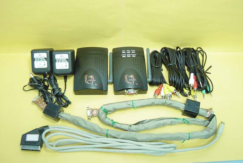
PVCGTP221
Jun 15, 2003PC To TV Transmitter
Equipment Class
DXX - Part 15 Low Power Communication Device Transmitter
PVCGTP218
Sep 30, 2002Audio Video Transmitter
Equipment Class
DXX - Part 15 Low Power Communication Device Transmitter
PVCGTP212
Jul 13, 2002Audio Video Transmitter
Equipment Class
DXX - Part 15 Low Power Communication Device Transmitter
PVCGTP224
Jun 02, 2002Wireless Audio Video Transmitter
Equipment Class
DXX - Part 15 Low Power Communication Device Transmitter
PVCP135
Nov 14, 2001Transmitter
Equipment Class
DXX - Part 15 Low Power Communication Device Transmitter