PVCP135Transmitter
Grantec Electronic Corp.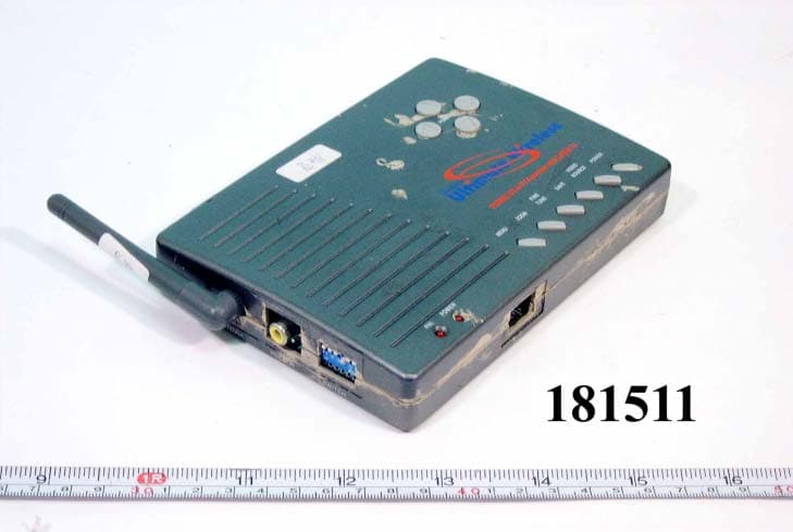
Click to zoom
Application Details
- Equipment Class
- DXX - Part 15 Low Power Communication Device Transmitter
- Date of Grant
- Nov 14, 2001
- Application Purpose
- Original Equipment
- Date of Application
- Nov 14, 2001
- Equipment Note
- Transmitter
- Frequency Range
- 2413.00000000 - 2468.00000000
- Company
- Grantec Electronic Corp.
- Country
- Taiwan
Documents & Files
Document Text
Text extracted from the exhibit documents filed with the FCC. Open a document above to read the original.
Users Manual
Grand ultimate wireless FCC ID : PVCP135 GRANDTEC ELECTRONIC CORP. The information in this document is subject to change without notice and does not represent a commitment on the part of the developer. This document contains materials protected by copyright. All rights are reserved. No part of this manual may be reproduced or transmitted in any form, by any means or for purpose without express written consent. FCC DECLARATION This device complies with Part 15 of the FCC Rules. Operation is subject to the following two conditions (1) this device may not cause harmful interference, and (2) this device must accept any interference received, including interference that may cause undesired operation. Federal Communications Radio Frequency Interference Statement. Note: This equipment has been tested and found to comply with the limits for a Class B digital device, Pursuant to part 15 of the FCC Rules. These limits are designed to provide reasonable protection against harmful interference when the equipment is operated in a residential installation. This equipment generates, uses and can radiate radio frequency energy and if not installed and used in accordance with the instruction manual may cause harmful interference to radio communications. However, there is no guarantee that interference will not occur in a particular installation. If this equipment does cause harmful interference to radio of television reception, which can be determined by turning the equipment off or on, the user is encouraged to try to correct the interference by one or more of the following measures: -Reorient or relocate the receiving antenna. -Increase the separation between the equipment and receiver. -Connect the equipment into an outlet on a circuit different from that to which the receiver is connected. -Consult the dealer or an experienced radio/TV technician for help. Notice : (1) The changes or modifications not expressly approved by the party responsible for compliance could void the user authority to operate the equipment. Shielded VGA cable must be used in order to comply with the emission limits. Printed in Taiwan R.O.C. All contents are subject to change without notice. All trademarks are the property of their respective owner. CONTENTS CHAPTER 1 WELCOME TO GRAND ULTIMATE WIRELESS ..... 1 1.1 INTRODUCTION................................................................ 1 1.2 FEATURES....................................................................... 1 1.3 MODE AND RESOLUTION TABLE........................................ 2 1.4 SYSTEM REQUIREMENT.................................................... 3 1.5 PACKAGE CONTENTS ...................................................... 3 CHAPTER 2 INSTALL GRAND ULTIMATE WIRELESS ........... 5 2.1 CONNECTORS OF GRAND ULTIMATE WIRELESS................. 6 2.2 BUTTONS & SWITCH OF GRAND ULTIMATE WIRELESS........ 6 2.3 CHANNEL SETTING......................................................... 7 2.4 INSTALLATION FOR IBM PC USER..................................... 7 2.5 STEP BY STEP CONNECTS................................................ 9 CHAPTER 3 TECHNICAL TIPS .................................... 12 CHAPTER 4 TROUBLE SHOOTING .............................. 13 ISSUE: 2001/07 VERSION: A P/N: 3413500
Users Manual
CH A P TER 1 z Adjus t ab le H - SIZE and V - S I ZE . WELCO M E T O GR A N D UL TIM A TE WIRELESS z 64 st age s c ontr o l : Br ight ne ss, C ontra st, H u e , Satur a ti on a d j u stm e nt. z 16 st age s c ontr o l : F i ne T une ( S har p nes s ) , Fli cker ad jus t m ent. 1 . 1 INTRODUCTION T hank y ou for purc has ing th e G r and U L T I M A T E W I R E LES S . G R A ND ULTIMA TE WIRELESS is a VGA to TV conv erter w i th an inte gra t ed 2.4G H z Wir e l ess Tr ansmitt e r & separ ate R e c e iv er . T r ansmit the co mput er’ s v i deo an d aud io to any remot e T V . It is id eal for Int e rne t or DVD/VCD m o v i e v i e w in g , pr es entat ion s , baby /pat ient m onit o rin g , b u rg lary det ect i on, thef t pr ev enti o n, or ho me/ c o m pany moni tori ng. z S t e r e o A u di o i n pu t f r om so u nd c a r d o r a n y au d i o d e vic e . z RF frequ ency : CH1 = 2 4 1 4 M Hz, CH2 =2 4 3 2 M H z , CH3 =2 4 5 0 M Hz , C H 4 =2468 MH z . z D e mod u lat i on M e thod: FM . z Freque ncy G e ner a tin g : P . L. L.. z Audio R e sp ons e : 2 0 H z ~ 20 k H z . z V i de o O u tpu t: 1Vp p / 7 5 oh m c o mpo s it e V i deo . z D i st an ce : O p en area is 100 m e ters, in door is 30 meter s . (A ct ual ra nge may v a ry depend ing on e n v i ron m e n t) 1.2 FEA T U R E S z Plug a nd D i spl a y , no s o f t w a re requir ed. 1 . 3 MODE A ND RE S O LUTION T A B L E z Support s four sele c t a bl e ch a nnels and m u ltiple r eceiv e r s , tr ansm it s , ISM Ba nd fro m 24 14~2 468M hz . T h is co nv erter s u pp ort s the fol l ow ing VG A di spl a y mod e s: Re s o l u ti o n 720 x 400 640 x 480 800 x 600 1024 x 768 11 5 2 x 864 1280 x 960 1280 x 1024 Ve r t i c a l Freque ncy (Hz ) 70 60, 70 , 72, 75 , 85, 10 0, 120 56, 60 , 70, 72 , 75, 8 5 , 100 60, 70 , 72, 75 60, 70 , 72, 75 6 0 6 0 z Simul t an eou s di sp lay on TV , Re m o te TV and VG A monitor . z Support s NTSC,NTSC-EIA J P A L-N, P A L, P A L-M, P A L-combinatio n-N and SECA M v i deo sy ste m . z Support s CVBS, S-VIDEO v i d eo out put s by sw itc h ch ang e ( v ia w i red conn ect i on s) . z T r ue 24 bit, true co lor d i gi tiz e r . z U s er c ontro ls: M E NU, ZOOM , FINE TUNE SA VE VIDEO S O URCE POWER & Pos i tion adju s t m ent s. T h is co nv erter s u pp ort s the fol l ow ing M A C display m o de s:(fo r M A C G 4 ,G 4 C ubic,G 3 ) z M enu key supp ort s Fr ee ze , S i ze , Bright ness , Contrast , Hu e , Saturat i on , V i deo S t and a rd, Fli cker , O S D color , Re s e t . Re s o l u ti o n 640 x 480 832 x 624 800 X 600 1024 X 768 1 152 X 864 z D I P Sw itch s uppor t s f u n c tio n s : C H A N N E L 1~ C H A N N E L 4 z LED ind i c a tor P A L & PO W E R . 1 2 Ve r t i c a l Freque ncy ( H z ) 60,66, 72, 7 5,85,1 00, 120 7 5 5 6 , 6 0 , 72, 75,85, 10 0 60,70, 75 60,70 4 S-V i de o c a ble V i de o c a ble . Audio cab l e. H cabl e for IBM PC Audio/ V i d e o C a ble R G B SC AR T w / A V C able T h is co nv erter fu lly s uppo rts A PPLE iM ac and iM AC D V computer dis p lay m ode s R e sol u tio n 6 4 0 x 4 8 0 800x 6 0 0 1024x 7 6 8 V e rtic al fr equ ency (H z ) 1 17 95 75 1.4 SY STEM R E QU IR EM EN TS z D e skt op or lap t op co mput er w i th H D 15 VG A s t and ard con n e c tio n . z T V or VC R that support s N T SC or P A L v i deo st an dard w i th comp os ite v i de o input (re quir ed f o r w i rele ss tra n sm is sio n ), ( o r) S-V i de o inpu t, (or) SC AR T inp u t conn ect o r . 1 . 5 P A CK A G E CONT E N TS T h is p a cka ge cont ain s th e fo ll ow ing ite m s: z U s er ’ s M anual For T x z G r and UL T I M A T E W I RE LESS Tx z S-V i de o c able z V i de o c able . z Audio cab l e. z H cabl e for IBM PC z Pow e r adapter (D C 6V/80 0 mA ) For Rx z G r and UL T I M A T E W I RE LESS R x z Audio/ V i d eo C a ble f o r R x z R G B SC AR T w i th A V cabl e (fo r Europe) z Pow e r adapter (D C 6V/80 0 mA ) 3 CH A P TER 2 INST A L L GR A ND UL TIM A TE WIRELESS 2 . 1 CONNE CTORS O F GR A N D ULTIM A TE W I RE LE SS z SCAN CNVTR : Conne c ts H cab l e t o PC, G r an d ULT I M A T E W I RELESS and moni tor. z AUDIO IN: Conne c ts t o s o un d dev i ce or a udio outp u t of DVD/ VCD /VCR. z VI DEO OU T : Conne c ts G r a nd ULT I M A T E W I RELESS to t h e Vi deo inp u t of TV . z S-OUT : C o nne c ts G r a nd U L T I M A T E W I R E LESS to y our T V su ppor t ing the S-VIDEO in put.(Re co mme nd for w i red con n e c tio n s) z DC IN : C o nne c ts w i th sup p li ed AC p o w er adapter. z VIDEO IN: Co n n e c ts t o yo u r vi d e o d e vi c e s u ch DVD/VCR/Ca m e ra fo r v i deo pa ss -thro ugh. T he follow i ng se ctio n s how s th e fun c tio n of co ntrol lin g th e G r and UL TIMA TE WIRELESS . Refer t o Fig u re 1 for th e Outli ne o f Grand UL T I M A T E W I RELESS. 2 . 2 BUTTONS & SW I T CH OF GR A N D ULTI M A TE W I RE LE SS z POWER : T o ggle be tw een po w e r on & off. z VIDEO SOURCE : T o ggles be tw een disp lay i n g the co nv erte d co mpu t er disp lay an d th e v i deo pa ss-t h r ough sour ce. z SA V E : Press th is butt on to sa v e curren t di spl a y and po siti on sett ing s . z FINE TUNE : Press th is t o fi ne -tune t he v i d eo i m ag e. z Z OOM : T oggle betw e en Zo o m an d N o rm al d i s p lay for co nv erted co mput er disp lay . z M E NU : Press butt o n to cy cl e throu g h th e fu nct i on s. T he f u n c tio n s are Fr eez e, HSIZE, VSIZE, Bri g htn e s s , Co ntrast , Hue, S a tura tio n , V i deo S t andard, Fli c k e r OSD c o l o r & Re s e t . z POSITION : Press up, dow n , l e ft an d rig h t b u tto n to adj u st t h e po siti on o f the conv erte d T V dis p lay . T h es e f o ur bu tton s a l so are use d to m a ke adju s t m ent s to the set t in gs in th e M E NU. FIG . 1 Outline of Grand UL TI M A TE WIRELESS 5 6 8 2 . 3 CH A NNE L S E TTING z DIP SWITCH: SW 1 S W 2 S W 3 SW 4 S W 5 S W 6 DE S C RIP T I O N DO W N ( O N ) CH A N NE L 1 D O W N (ON) CH A N NE L 2 DO W N (ON) CH A N NE L 3 DO W N ( O N ) CH A N NE L 4 DO W N…
Text truncated - open the document above for the full version.
External Photos
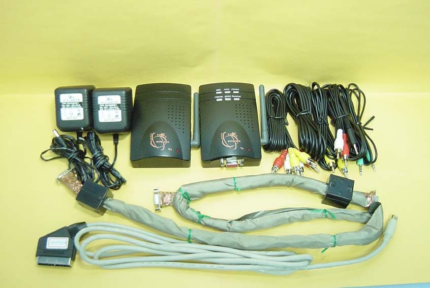
FC C ID : PVC P135 FRONT SIDE OF EUT N u mber 1 181511- 01.jpg FC C ID : PVC P135 REA R SIDE OF EUT N u mber 2 181511- 02.jpg FC C ID : PVC P135 FRONT SIDE OF A D A P TER N u mber 3 181511-07. j pg FC C ID : PVC P135 R E A R SID E OF A D A P TER ( R ef erence M odif i cat ion N o .1) N u mber 4 1 181511-08. j p g
ID Label/Location Info
EXHIBIT A. FCC ID LABEL FCC ID:PVCP135 PVCP135 Note: 1. Material and thickness:2 mi 1, white 2. Glue information : Permanent adhesive 3. Text color is black 4. Scale: 1:1
ID Label/Location Info
FCC ID: PVCP135 FCC ID Location
Internal Photos
FC C ID : PVC P135 M echanical C onst r uct i on N u mber 1 181511- 03.jpg FC C ID : PVC P135 M echanical C onst r uct i on ( R ef erence M odif i cat ion N o .2, 3, 4) N u mber 2 3 4 2 181511- 11.jpg FC C ID : PVC P135 Front side of Main Board ( R e f e r e n c e M o d i f i c a t i o n N o . 5 , 6 , 7 ) N u m b e r 3 5 6 7 142301- 05.jpg FC C ID : PVC P135 R ear side of M a in B o ard N u mber 4 181511- 06.jpg FC C ID : PVC P135 M echanical C onst r uct i on ( R ef erence M odif i cat ion N o .7, 8) N u mber 5 9 8 8 9 181511- 09.jpg FC C ID : PVC P135 M echanical C onst r uct i on N u mber 6 181511- 10.jpg
Operational Description
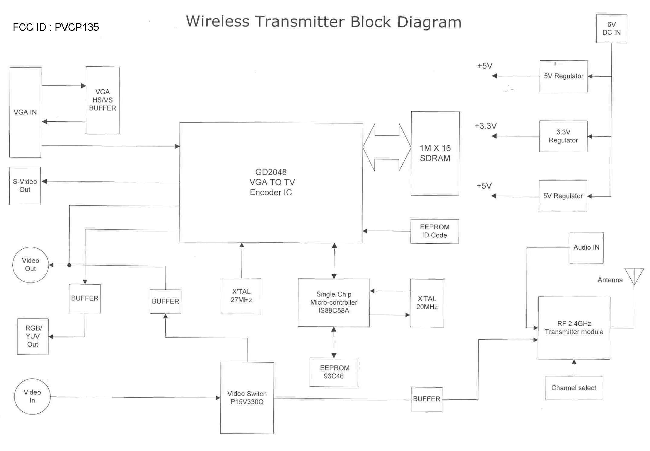
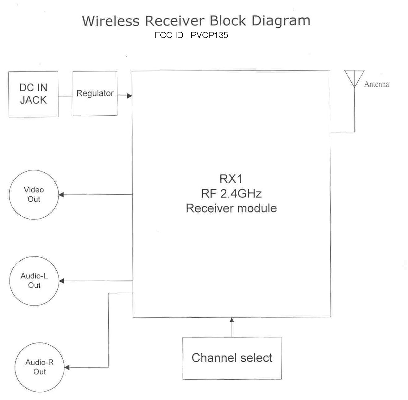
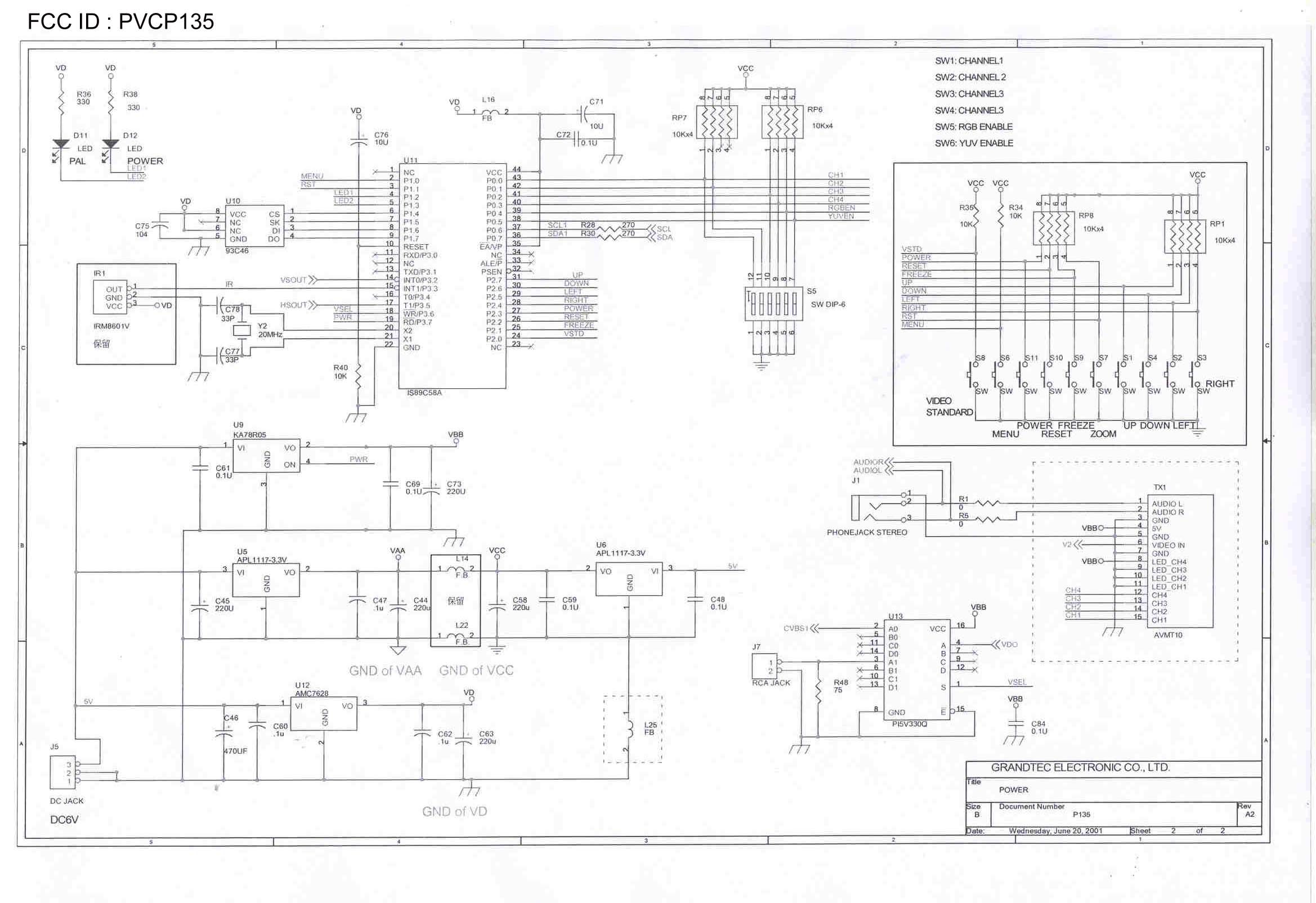
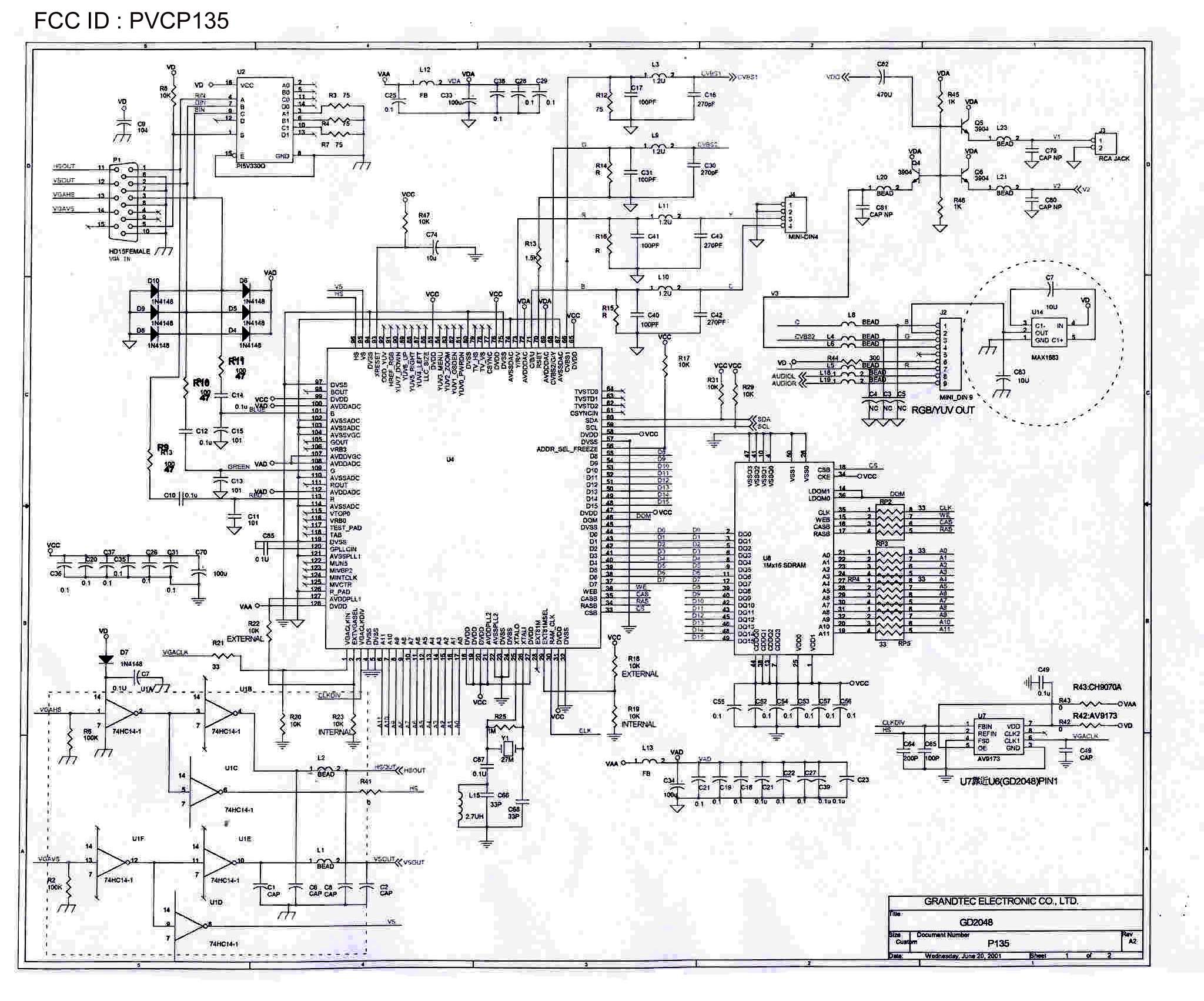
FCC ID : PVCP135 The Circuit Work of Wireless (P135) This device converts the signal from VGA to video, then sends the video signal from TX1 (RF module) to receiver. The local end can be also monitored with small display devices. The VGA signal input from P1Jack. D4~D10 (IN4148 Diode) are applied as the limiters. By way of R9, R10, R11, C12, C10, C14, the signal enters U4 (GD2048) for process. During the process (ex. ZOOM adjustment), the image signal is stored temporarily at U8 (IMX16 SDRAM) U1 (74HC14) is applied as the buffer for H-SYNC and V-SYNC, to move the Jack of monitor. U4 is mainly applied to convert the VGA signal to composite video or S-video or RGB signals. Then U11 (single-chip) effects ZOOM IN/OUT, Color Adjustment, Sharpness Adjustment...etc. The processed composite signal will be sent out by Pin 66, to match the impedence with R12, to comply with EMI with L3, C17, C16, and goes into U13 (P15V330Q) electronic switch. U13 accepts external video in or internal VGA cable from PC. The INPUT source is determined by pushing the function button (Video Source) on the control panel. Before entering the transmitter, the signal passes through Q6 to upgrade the electric current. Then becomes 2.4GHz signal in TX1 and is transmitted here. Most of the oscillation frequency of U11 is at 20MHz. It is generated from XTAL (20MHz). The main purpose is to decode the demands from function buttons, then pass to U4 through the I2C interface (Pin 36, 37). U9, U5, U12 are regulators. The main purpose is to supply the work voltage to all of the chip-sets. The work frequency of U4 is 27MHz. It generates the pulse with Y1 (27MHz) XTAL.
Test Report
FCC TEST REPORT Report No. : F181511 TEST REPORT for 47 CFR, Part 15, Subpart C Equipment : Grand ultimate wireless Model No. : P135, P157, Grand ultimate wireless FCC ID : PVCP135 Filing Type : Certification Applicant : GRANDTEC ELECTRONIC CORP. 8F-1, No. 16, Jian Ba Rd., Chung Ho City, Taipei Hsien 235, Taiwan, R.O.C. The test result refers exclusively to the test presented test model / sample. Without the written authorization of the test lab., the Test Report may not be copied. Certificate or Test Report must not be used by the applicant to claim the product in this test report endorsement by NVLAP or any agency of U.S. government. SPORTON International Inc. 6F, No.106, Sec. 1, Hsin Tai Wu Rd., Hsi Chih, Taipei Hsien, Taiwan, R.O.C. SPORTON International Inc. TEL : 886-2-2696-2468 FAX : 886-2-2696-2255 FCC TEST REPORT Report No. : F181511 Table of Contents History of this test report....................................................................................................................................ii CERTIFICATE OF COMPLIANCE........................................................................................................................1 1. General Description of Equipment under Test.............................................................................................2 1.1. Applicant....................................................................................................................................................................................2 1.2. Manufacturer..............................................................................................................................................................................2 1.3. Basic Description of Equipment under Test................................................................................................................................2 1.4. Feature of Equipment under Test...............................................................................................................................................3 2. Test Configuration of Equipment under Test...............................................................................................4 2.1. Test Manner...............................................................................................................................................................................4 2.2. Description of Test System.........................................................................................................................................................4 2.3. Connection Diagram of Test System..........................................................................................................................................7 2.4. Band edges measurement.........................................................................................................................................................8 3. Test Software.................................................................................................................................................10 4. General Information of Test..........................................................................................................................11 4.1. Test Facility..............................................................................................................................................................................11 4.2. Standard for Methods of Measurement....................................................................................................................................11 4.3. Test in Compliance with...........................................................................................................................................................11 4.4. Frequency Range Investigated.................................................................................................................................................11 4.5. Test Distance...........................................................................................................................................................................11 5. Test of Conducted Powerline.......................................................................................................................12 5.1. Major Measuring Instruments...................................................................................................................................................12 5.2. Test Procedures.......................................................................................................................................................................13 5.3. Typical Test Setup Layout of Conducted Powerline..................................................................................................................14 5.4. Test Result of AC Powerline Conducted Emission...................................................................................................................15 6. Test of Radiated Emission............................................................................................................................20 6.1. Major Measuring Instruments...................................................................................................................................................20 6.2. Test Procedures.......................................................................................................................................................................21 6.3. Typical Test Setup Layout of Radiated Emission......................................................................................................................22 6.4. Test Result of Radiated Emission.............................................................................................................................................23 7. EMI Suppression Component List....................…
Text truncated - open the document above for the full version.
Test Setup Photos
FCC TEST REPORT Report No. : F181511 1.1. Photographs of Conducted Powerline Test Configuration z The photographs show the configuration that generates the maximum emission. VGA INPUT FRONT VIEW REAR VIEW SPORTON International Inc. FCC ID : PVCP135 TEL : 886-2-2696-2468 Page No. : 1 of 6 FAX : 886-2-2696-2255 Issued : Sep. 20, 2001 FCC TEST REPORT Report No. : F181511 SIDE VIEW SPORTON International Inc. FCC ID : PVCP135 TEL : 886-2-2696-2468 Page No. : 2 of 6 FAX : 886-2-2696-2255 Issued : Sep. 20, 2001 FCC TEST REPORT Report No. : F181511 VCR INPUT FRONT VIEW REAR VIEW SPORTON International Inc. FCC ID : PVCP135 TEL : 886-2-2696-2468 Page No. : 3 of 6 FAX : 886-2-2696-2255 Issued : Sep. 20, 2001 FCC TEST REPORT Report No. : F181511 SIDE VIEW SPORTON International Inc. FCC ID : PVCP135 TEL : 886-2-2696-2468 Page No. : 4 of 6 FAX : 886-2-2696-2255 Issued : Sep. 20, 2001 FCC TEST REPORT Report No. : F181511 1.2. Photographs of Radiated Emission Test Configuration z The photographs show the configuration that generates the maximum emission. VGA INPUT FRONT VIEW REAR VIEW SPORTON International Inc. FCC ID : PVCP135 TEL : 886-2-2696-2468 Page No. : 5 of 6 FAX : 886-2-2696-2255 Issued : Sep. 20, 2001 FCC TEST REPORT Report No. : F181511 VCR INPUT FRONT VIEW REAR VIEW SPORTON International Inc. FCC ID : PVCP135 TEL : 886-2-2696-2468 Page No. : 6 of 6 FAX : 886-2-2696-2255 Issued : Sep. 20, 2001
Contact Information
Applicant
Johnson Liao(Manager R&D Dept.)
Test Firm
SPORTON International IncKathy Lin
Technical Specifications
| # | Rule Parts | Frequency Range | Power Output |
|---|---|---|---|
| 1 | 15C | 2.41 GHz - 2.47 GHz | - |
Other Applications from Grantec Electronic Corp.
PVCGTP221
Jun 15, 2003PC To TV Transmitter
Equipment Class
DXX - Part 15 Low Power Communication Device Transmitter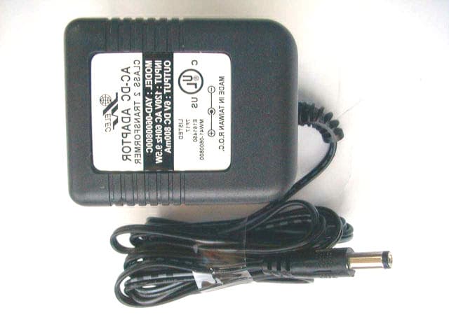
PVCGTP218
Sep 30, 2002Audio Video Transmitter
Equipment Class
DXX - Part 15 Low Power Communication Device Transmitter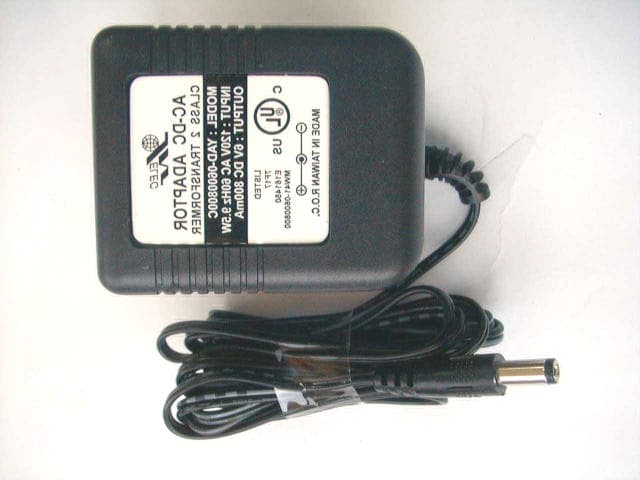
PVCGTP212
Jul 13, 2002Audio Video Transmitter
Equipment Class
DXX - Part 15 Low Power Communication Device Transmitter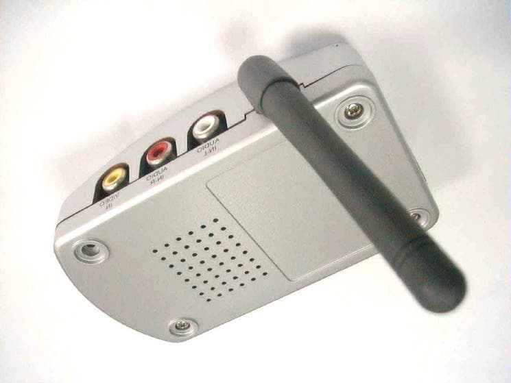
PVCGTP224
Jun 02, 2002Wireless Audio Video Transmitter
Equipment Class
DXX - Part 15 Low Power Communication Device Transmitter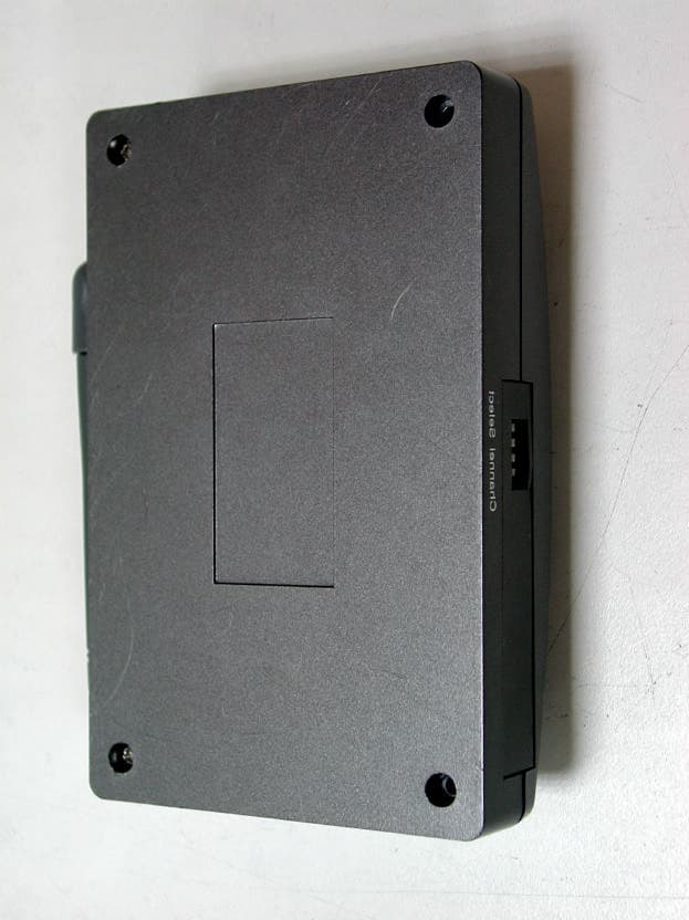
PVCGTP205
Dec 18, 2001Audio Video Transmitter
Equipment Class
DXX - Part 15 Low Power Communication Device Transmitter