PVQDSCAR001Remote Control Car Alarm Transceiver
drakesystem co.,ltd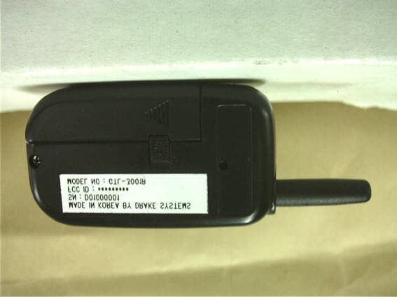
Click to zoom
Application Details
- Equipment Class
- DSR - Part 15 Remote Control/Security Device Transceiver
- Date of Grant
- Oct 22, 2001
- Application Purpose
- Original Equipment
- Date of Application
- Oct 22, 2001
- Equipment Note
- Remote Control Car Alarm Transceiver
- Frequency Range
- 433.92000000 - 433.92000000
- Company
- drakesystem co.,ltd
- Country
- South Korea
Documents & Files
Document Text
Text extracted from the exhibit documents filed with the FCC. Open a document above to read the original.
Users Manual
USERS MANUAL GTL-3001 Operating Instructions Table of Contents 1. Unpacking and Checking Equipment 2. Operation Instructions 3. FCC Information 4. FCC Label Information 1. Unpacking and Checking Equipment Carefully unpack the equipment and its accessories. 1). Remote controller 2). Base communication module 3). Main controller 4). kinds of Harness Assembly 5). Shock sensor 2. Operation Instructions 2-1. ARMING The car alarm system checks the intrusion into the car in the arm mode (shock & door open) and pages it the remote controller, and then, it alerts for 45 seconds with siren and light flashing. After alarm, it returns to arm mode. 2-1-1. Pressing the “LOCK” button : Press “LOCK” button shortly, and the Car locks the door and goes into arm mode with audible chirp and visual light flashing. The LED of communication module will be turned on for 5 seconds ( ARM delay mode ) and then start flashing ( ARM mode ). The remote controller shows green LED flashing and sounds one short beep. If you press the “LOCK” button under “NO CHIRP MODE”, the car acts the same way above, but without chirp. 2-1-2. Automatic passive arming ( When the car is set to passive arming ) : When the key is pulled out of key box and all doors are closed, the system will arm automatically after 30 seconds. When the car is armed, it acts like above procedures. Note 1: Passive arming is selectable feature that can be turned ON or OFF by your alarm dealer / installer. Please check the installation guide. 2-1-3. Special functions when entering into arming : When the door is opened and the “LOCK” button is pressed, the car alerts 4 chirps & 4 light flashing. When the shock sensor is triggering and the “LOCK” button is pressed, the car alerts 3 chirps & 3 light flashing. The car does not alert this status even though it is in arm mode, but , if the door is closed and opened again or if the shock sensor is muted and triggered again, the car sends alarm signal. 2-2. DISARMING 2-2-1. Pressing the button “UNLOCK” shortly disarms the car. When the car is disarmed, it unlocks the door with two audible chirps and visual light flashing. The remote controller shows green LED flashing and sounds short beeps two times. If you press the “UNLOCK” button under “NO CHIRP MODE”, the car acts the same way above, but without chirp. 2-2-2. The car memorizes the status of intrusion ( door open )in the arm mode and alerts it when the car is disarmed. The car alerts 4 times light flashing and 4 times chirps. The remote controller shows 4 times of green LED and long beeps. The car alerts 3 chirps and 3 light flashing for the triggering of shock sensor during arm mode. 2-3. CAR FIND When the button “AUX” is pressed shortly, the remote car shows audible beep and visual lighting. The remote controller shows flashing of green LED and sounds short beep four times. 2-4. PANIC (FOR YOUR PERSONAL SAFETY ) When the button “LOCK” or “UNLOCK” is pressed more than 2 seconds, the car will start alarming and flashing for 45 seconds. The panic can be removed by pressing any button and it is helpful for your personal safety. 2-5. TRUNK OPEN Pressing the button “ASTERISK” for more than 2 seconds can open the trunk of the car. At that time, the remote controller flashes green LED 5 times and sounds short beep 5 times. 2-6. VALET MODE Valet mode is used to prevent from alarm system arming or triggering. The alarm should be put into valet mode when the vehicle is being serviced. Press the button ”AUX” more than 2 seconds during the car key is in the position of “ACC” in the key box, then VALET mode is activated. At the VALET mode, the LED on the base communication module turns ON continuously and the remote controller turns on green LED and sounds one dual beep. And also the car alerts audible chirp with visual light flashing. Now the car is in VALET mode. Only “LOCK” “UNLOCK” & “AUX” can be activated. Even though the “LOCK” is activated, the car does not enter into ARMING during VA LE T m od e. As the VALET mode is toggle function, the car can be return to the DISARM mode when the button “AUX” is pressed once again at the same condition. When the VALET mode is removed and returns to the DISARM mode, the car alerts audible chirp with visual light flashing. And the remote controller shows the green LED flashing and 2 times dual beeps. 2-7. PROGRAMMABLE FUNCTIONS There are 4 programmable functions for the operation of the caralarm system. These functions can be activated or de-activated by remote controller. All of these functions can be programmed when the key is located on “ACC” state in the key box. All of them are toggle functions and the default setting is “ON”. When these functions are activated, you can hear “BEEP_HI_LO” once. When these are de-activated, you can hear “BEEP_HI_ LO” twice. 2-8. CHIRP / NO CHIRP When the button “LOCK” is pressed twice shortly (double click) during the car key is in “ACC” position in the key box, the CHIRP sound will be activated or de-activated with the green LED and “BEEP_HI_LO”. The siren in the mode of alarm and panic cannot be removed even though the “CHIRP” is de-activated. 2-9. ADJUSTMENT OF LOCK TIME When the button “ UNLOCK” is pressed twice shortly, this function can be changed. The default is 3 seconds and the other is 0.8 seconds. As this function is set properly at the time of installation, you need not use this function. 2-10. IGNITION LOCK When the button “ASTERISK” is pressed twice shortly, this function can be changed. The car locks the door automatically during driving when it is activated, but unlocks the door during driving when it is de-activated. 2-11. ON / OFF OF SENSOR When you press the button “AUX” twice shortly, you can toggle this function. When the sensor is activated, the car can be triggered by the sensor and alarms the triggering of shock at the arm mode. But the car ignores the triggering of sensor when de-activated. 2-12. PAGING FROM CAR The paging from the car to the remote controller is unique …
Text truncated - open the document above for the full version.
Block Diagram
3. ΓΤΛ−3001Ρ ΒΛΟΧΚ ∆ΙΑΓΡΑΜ ΒΦΘ67Ω ΦΙΛΤΕΡΧΘΣΦ434Μ ΑΣΚ ΡΕΧΕΙςΕΡ (ΤΑ31142) ΦΙΛΤΕΡ10.7ΜΗζ ΛΟΧΑΛ ΟΣΧ423.22ΜΗζ 1 ΑΝ∆ ΜΥΛΤΙΠΛΙΕΡ ΒΦΘ67Ω ΟΣΧ 433.92ΜΗζ ΤΞ ΠΟΩΕΡΧΟΝΤΡΟΛ ΡΞ ∆ΑΤΑΤΞ ∆ΑΤΑ Χ ΠΥ ΠΙΧ16Χ72Α ΠΟΩΕΡ ΥΠ ΧΙΡΧΥΙΤ ΡΗ5ΡΙ302Β1.5ς ΤΟ 3ς ΣΩ1∼4 ΛΕ∆ ΒΥΖΖΕΡ
External Photos
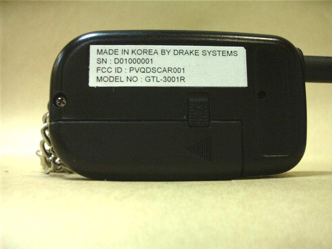
GTL-3001R PHOTO (TOP SIDE) GTL-3001R PHOTO (BOTTOM SIDE)
Internal Photos
GTL-3001R PHOTO (RF PCB TOP SIDE) GTL-3001R PHOTO (RF PCB BOTTOM SIDE) GTL-3001R PHOTO (CPU PCB TOP SIDE) GTL-3001R PHOTO (CPU PCB BOTTOM SIDE) GTL-3001R PHOTO (ANTENNA)
Operational Description
3. OPERATIONG DESCRIPTION The circuit description of remote controller 2001/7/20 The remote controller consists of 3 parts. The first is RF stage which transmits and receives the RF signal and it is located in the RF PCB Assy. The second is CPU and it’s peripherals and it is located in the DIGITAL PCB Assy. The third is power boosting circuit which is located in the DIGITAL PCB Assy. 1. RF PCB Assy The RF PCB Assy is connected with the DIGITAL PCB Assy with 2 connectors, CON3 & CON4. The operating power and control signal feeds from DIGITAL PCB Assy through connectors and the receiving data sends to the DIGITAL PCB Assy through connectors. 1) The TX circuit This remote controller is using ASK method for data transmission and data receiving. The TX circuit has oscillating circuit, amplifier , antenna switch and power enable circuit. The oscillating circuit is composed of Tr ( Q1 ) and SAW resonator ( CR2 / 433.92MHz ) and several passive components ( C20, C21, L7, L15, C53, R7, R8, R9 ). The power feeds through Q3 when the transmitting data is high and it is disable when the transmitting data is low or receiving circuit is enabled. The oscillating circuit oscillates 433.92MHz directly and supplies to the amplifier circuit. The amplifier circuit is composed of Tr(Q2) and several passive components ( L9, TC1, C22, C23, C27, R10, R11 ). It amplifies the RF signal and supplies to the antenna switching circuit. The antenna switching circuit is used to prepare the path of RF signal, for example, it passes RF signal from TX circuit to antenna and prevents RF signal from going to the RX circuit when TX mode and vice versa. 2) The RX circuit The RX circuit has antenna switching circuit, pre-amplifier, filters and demodulators. The received RF signal in the antenna is supplied to the pre-amplifier through antenna switching circuit. As the received RF signal is very weak, it is amplified by pre-amplifier. The pre-amplifier is composed of Tr ( Q7 ) and several passive components ( L13, R29, R30, C47, L1, C1 ). The amplified RF signal is supplied to the receiving IC ( U1 ) through SAW filter. The filter passes only wanted signal and eliminates spurious signals. The receiving IC has oscillator circuit and demodulating circuit in it. The CR1 and several passive components are used to make local signal. The local signal and receiving RF signal is mixed inside of U1 and makes IF signal. IF signal is filtered by CF2 ( 10.7MHz ) and fed to the demodulating circuit. The demodulating circuit makes recovered signal ( original data signal ) and the recovered signal is fed to the CPU through CON3. The receiving IC is usually in sleep mode and wakes up when needed. The wake-up time is controlled by CPU. 2. DIGITAL PCB Assy The CPU and it’s peripherals and D/D converter circuit are located in the DIGITAL PCB Assy. 1) CPU and peripherals The CPU ( U2 / PIC16C72A ) controls all the circuit of remote controller. It has 4 key buttons for key input, 2 LED’s to display and one buzzer to alert tones as a peripherals. Also, it generates transmitting data ( RC1 ) and checks the receiving data ( RA4 ). The resonator ( CR3 / 2MHz ) is used to make clocks for the CPU. The CON5 is used for the programming of CPU. 2) D/D circuit This remote controller uses battery of AAA 1.5V. 1.5V is not enough to operate the active components such as CPU and receiving IC. So, power boosting circuit is needs to make 3.0V. The IC ( U3 RH5RI302B ) and several components ( CH1, Q5, C42, R25, D6, C40, C41, C43 ) are used to boost power supply to 3.0V.
Schematics
3. ΣΧΗΕΜΑΤΙΧ VCC (+3V) VCC(3V) VCC(3V) VCC(3V) VCC(3V) VDD(+1.5V) VCC(+3V) VDD(+1.5V) VCC ( + 3 VCC(+3V) VCC(+1.5V) VCC(+3V) TX DATA RX DATA ANT1 ANTENNA VDD (+1.5V)GND D1 KDS114 D6 RB411D C4147/4(T) + CH1100uH L11 12nH U3RH5RI302B VOUT ON/OFF VSS VIN EXT D3 KDS114 C421000P R251k Q5KTC3876 C40104 L327n R4270 CR1 423.22M R510K L45n6 L55n6 R61K2 L212nH CF1CQSF434M 3 2 1 R1150 R2470 Q1BFQ67W Q2 BFQ67W L7 12nH L918nH CR2 433.92M R810K R7100 R11 0 TC18P R12 1K L1027nH Q3 KTA1505S R1410K R1310K R1010K Q4 KTA1505S D4RED LED R2333K L8 47nH R9680 L12 33nH R15470K D2 KDS160 C15 10/16(T) + C43 47/4(T) + R19470 S3LP15 R2133K BZ1 BUZZER CF2 10.7M 3 2 1 R1733K S4LP-15 R2233K S1LP15 R20470 CR32.00M D5GREEN LED U1 UAA3220TS OGND 1 OSE 2 OSB 3 VCC 4 OSC 5 TEM 6 TN 7 TP 8 PWD 9 DEMO1 10 DEMO2 11 GND 12 CGND 13 DATA 14 CPA 15 CPB 16 CPC 17 RSSI 18 LFB 19 MIXIN 23 MGND 24 FA 22 VCCI 21 LIN 20 R2433K S2LP15 R18470R1610K U2PIC16C72A MCLR- 1 A/D 2 RA1 3 RA2 4 RA3 5 RA4 6 RA5 7 VSS1 8 OSC1 9 OSC2 10 RC0 11 RC1 12 RC2 13 RC3 14 RC4 15 RC5 16 RC6 17 RC7 18 VSS2 19 VDD 20 RB0 21 RB1 22 RB2 23 RB3 24 RB4 25 RB5 26 RB6 27 RB7 28 C440.1 C3622P C350.1 C8474 C60.01 C7 332 C5473 C3102 C2N.C C16P C4102 C9102 C10680P C12104 C131.5P C168P C17102 C202P C18 N.C C215P C143P C24102 C25 102 C19150P C26102 C22 1P C233P C2733P C284P C347P C33N.C C294P C32680P C313P C302P C3722P C390.1 C38102 R2610K R2710K j1rx test jumperj2tx test jumper C45104 R301K L1318nH C46470P Q7 BFQ67W R29120K C472P L1N.C C5033P C4833P CON14PIN(M) . 1 . 2 . 3 . 4 CON4 4PIN(P) . 1 . 2 . 3 . 4 CON24PIN(M) . 1 . 2 . 3 . 4 CON3 4PIN(P) . 1 . 2 . 3 . 4 C524P R280 C51104 L1433nH L1533nH .. C5312P R312.2K
Test Report
KTL Korea Testing Laboratory Page 1 of 14 TEST REPORT This test report only responds to the tested sample and shall not be reproduced except in full without written approval of the Korea Testing Laboratory. Tested and reported by Reviewed by Jeong-Min Kim , Senior Engineer Won-Seo Cho, EMC Team Leader KOREA TESTING LABORATORY FG101-01-02-00 222-13, Guro-Dong Guro-Gu Seoul Korea 152-053 http://www.ktl.re.kr Ref. Report No. 01-341-042-01 Name and address of the applicant Drake Systems Co., Ltd. Acetechno 804, Yangpyung-dong, Youngde ungpo-ku, Seoul, 150-103, Korea Standard / Test regulation FCC Part 15, Subpart C Test result Pass Incoming date : August 13, 2001 Test item( s) ; Security/Re mote Control Transmitter (Car Alarm System) Model/type ref. ; GTL-3001R Manufacturer ; Drake Systems Co., Ltd. Additional information ; -Re quire d Aut ho riz atio n : Ce rtificatio n -FCC ID. : PVQDSCAR001 - Note : Te st re port(Ve rificatio n) of Re ce ive r po rtio n of t his unit is iss ue d o n Re f. Re port No. 01-341-041-02. Test date : August 29, 2001Issue date : September 4, 2001 Ref. Report No. 01-341-042-01 Page 2 of 14 TABLE O F CONTENTS I. GENERAL INFORMATION.......................................................................................3 1. Grantee’s Name and Mailing Address 2. Manufacturer's Name and Mailing Address 3. Equipment Descriptions 4. Rules and Regulations 5. Measuring Procedure 6. Date of Measurement α. GENERAL REQUIREMENTS OF THE EUT..................................................................4 1. Labelling Requirement (Section 15.19) 2. Information to User (Sections 15.21) 3. Special Accessories (Section 15.27) 4. Compliant Conditions (Section 15.231) β. RADIATED EMISSION MEASUREMENT (Section 15.231)...........................................6-12 1. Test Procedure 2. Photograph of the test configuration 3. Sample Calculation 4. Measurement Data 5. Reference Data χ. OCCUPIED BANDWIDTH MEASUREMENT (Section 15.231)..........................................13 δ. TEST EQUIPMENTS USED FOR MEASUREMENT.......................................................14 Ref. Report No. 01-341-042-01 Page 3 of 14 . GENERAL INFORMATION 1. Grantee’s Name and : Drake Systems Co., Ltd. Mailing Address Acetechno 804, Yangpyung-dong, Youngdeungpo-ku, Seoul, 150-103, Korea 2. Manufacturer's Name and : Drake Systems Co., Ltd. Mailing Address Acetechno 804, Yangpyung-dong, Youngdeungpo-ku, Seoul, 150-103, Korea 3. Equipment Descriptions 3.1 Operating Frequency : 433.92 MHz 3.2 Type of Emission : Pulse Code Signal 3.3 Power Supply: DC 1.5V(Battery) 4. Rules and Regulations: FCC Part 15, Subpart C 5. Measuring Procedure: ANSI C63.4-1992 6. Place of Measurement: Absorber-lined Room (KTL) 7. Date of Measurement 7.1 Line Conducted: Not Applicable 7.2 Radiated Emission : August 29, 2001 Ref. Report No. 01-341-042-01 Page 4 of 14 . GENERAL REQUIREMENTS O F THE EUT 1. Labelling Requirement (Section 15.19) This device complies with Part 15 of the FCC Rules. Operation is subject to the following two conditions: (1) this device may not cause harmful interface, and (2) this device must accept any interference received, including interference that may cause undesired operation. 1.1 Location of Label : User’s Guide Manual 1.2 How Applied : Printed 2. Information to User (Section 15.21) The following or similar statements were provided in the manual for user instruction. Please refer page 10 of the attached manual for details. CA UT ION : A ny c ha nges or modifications i n cons truc tion o f this device w hich are not e xpressly approved by the party responsible for compliance could void the user's authority to operate the equipment. 3. Special Accessories (Section 15.27) 3.1 Were the special Accessories provided? [ ] yes, [ x ] no 3.2 If yes, details for the special accessories are as follows : 3.3 If yes, were the appropriate instructions provided on the first page of the text concerned with the installation of the device? [ ] yes, [ ] no 3.4 Are these accessories provided of the type which can be readily obtained from multiple retail outlets ? [ ] yes, [ ] no And therefore does the manual specify what additional components or accessories are required to used in order to comply with the Rules? [ ] yes, [ ] no Ref. Report No. 01-341-042-01 Page 5 of 14 4. Compliant Conditions (Section 15.231) 4.1 Was the EUT used for continuous transmissions, such as voice or video, and data transmission ? [ ] yes, [ x ] no 4.2 Was the EUT manually operated ? [ x ] yes, [ ] no If yes, did the EUT employ a switch that would automatically deactivate the transmitter within not more than 5 seconds of being released ? [ x ] yes, [ ] no 4.3 Was the EUT automatically activated ? [ ] yes, [ x ] no If yes, did the EUT cease transmission within 5 seconds after deactivation ? [ ] yes, [ ] no 4.4 Was the EUT used for periodic transmissions at regular predetermined intervals ? [ ] yes, [ x ] no Ref. Report No. 01-341-042-01 Page 6 of 14 . RADIATED EMISSION MEASUREMENT (Section 15.231) 1. Test Procedure 1.1 Preliminary Testing for Reference Preliminary testing was performed in a KTL absorber-lined room to determine the emission characteristics of the EUT. The EUT was placed on the wooden table which has dimensions of 0.8 meters in height, 1 meter in length and 1.5 meters in width. Receiving antenna (Biconical antenna : 30 to 300 MHz, Log-periodic antenna : 200 to 1000 MHz or Horn Antenna : 1 to 18 GHz) was placed at the distance of 1 meter from the EUT. An a tte mpt was made to ma xi mize the e mission level with the various confi gurations o f the EUT. Emission levels from the EUT with various configurations were examined on a spectrum analyzer connected with a RF amplifier and graphed by a plotter. 1.2 Final Radiated Emission Test at an Absorber-Lined Room The final measurement of radiated field strength was carried out in a KTL absorber-lined Room that was listed up at FCC according to the "Radiated Emissions Testing" procedure spec…
Text truncated - open the document above for the full version.
Test Setup Photos
Ref. Report No. 01-341-042-01 Page 7 of 14 2. Photograph of the test configuration 3. Sample Calculation The measured field strength was determined by averaging over one complete pulse train including blanking interval because the pulse train time of the EUT (= 85.0 msec) did not exceed 0.1 seconds (15.35(c)). See graphs of page 12 . With the resolution bandwidth set at 30 kHz, the EUT produces a pulse spectrum on the spectrum analyzer because the bandwidth of the analyzer is greater than or equal to the PRF (= 417 Hz). Therefore, as mentioned in HP Application Note 150-2 (page 11), the pulse desensitization( p ) equals zero and the display amplitude is essentially a peak level.
Contact Information
Applicant
Hongtack Kim(director)
Test Firm
Korea Testing LaboratoryJeong-Min Kim
Technical Specifications
| # | Rule Parts | Frequency Range | Power Output |
|---|---|---|---|
| 1 | 15C | 433.92 MHz - 433.92 MHz | - |
Other Applications from drakesystem co.,ltd
PVQDSCAR004
May 26, 2004RF Keyless Entry System
Equipment Class
DSC - Part 15 Security/Remote Control Transmitter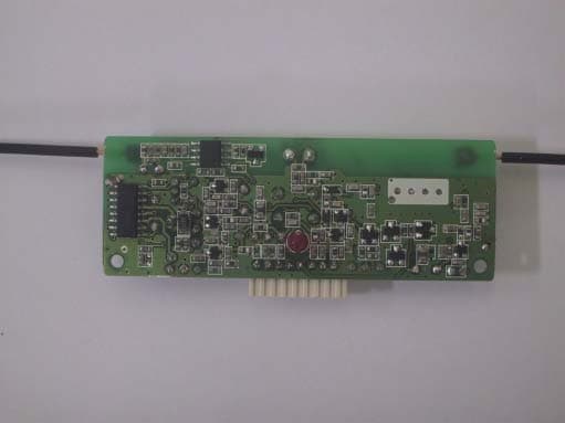
PVQDSCAB004
May 26, 2004RF Keyless Entry System
Equipment Class
DSC - Part 15 Security/Remote Control Transmitter
PVQDSCAB002
Jan 17, 2002Car Pager
Equipment Class
CYY - Communications Receiver used w/Pt 15 Transmitter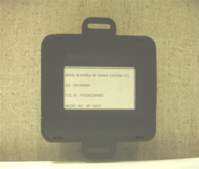
PVQDSCAR003
Jan 17, 2002Car Pager
Equipment Class
DSC - Part 15 Security/Remote Control Transmitter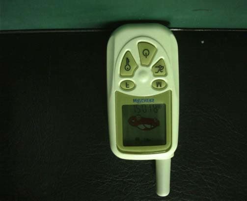
PVQDSCAR002
Dec 19, 2001Car Alarm Remote Transceiver
Equipment Class
DSR - Part 15 Remote Control/Security Device Transceiver