PW3102RF Door Lock
Hafele America Co.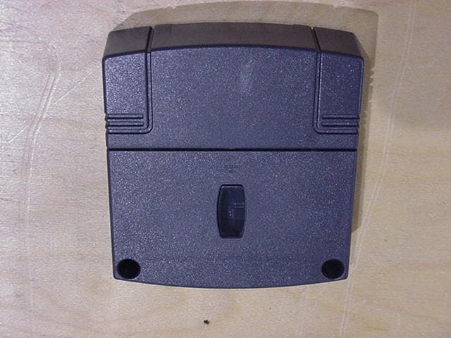
Click to zoom
Application Details
- Equipment Class
- DCD - Part 15 Low Power Transmitter Below 1705 kHz
- Date of Grant
- Feb 12, 2002
- Application Purpose
- Original Equipment
- Date of Application
- Feb 12, 2002
- Equipment Note
- RF Door Lock
- Frequency Range
- 0.13400000 - 0.13400000
- Company
- Hafele America Co.
- Country
- United States
Documents & Files
Document Text
Text extracted from the exhibit documents filed with the FCC. Open a document above to read the original.
Users Manual
Hafele America Co. 1 Document No.: DIA.DPR.013 Dialock Dept. Document Date: 12/17/2001 (888) 437-7477 Print Date: 2/8/2002 LockerLock Mounting Instructions and Operation, Simple Mode NOTICE: Any changes or modifications made to the LockerLock will void the user’s authority to operate this equipment in compliance with FCC regulations. NOTE: This equipment has been tested and found to comply with the limits for a Class B digital device, pursuant to Part 15 of the FCC Rules. These limits are designed to provide reasonable protection against harmful interference in a residential installation. This equipment generates, uses and can radiate radio frequency energy and, if not installed and used in accordance with the instructions, may cause harmful interference to radio communications. However, there is no guarantee that interference will not occur in a particular installation. If this equipment does cause harmful interference to radio or television reception, which can be determined by turning the equipment off and on, the user is encouraged to try to correct the interference by one or more of the following measures: Reorient or relocate the receiving antenna. Increase the separation between the equipment and receiver. Connect the equipment into an outlet on a circuit different from that to which the receiver is connected. Consult the factory or an experienced radio/TV technician for help. Set-up: Set-up of the Dialock LockerLock unit begins with unpacking and inspecting the unit. Remove and discard the box and packing material. Inspect the unit and all other components for obvious signs of damage. Contact the dialock department for questions or problems. The following list includes the article numbers along side the components packed in the set: • 1 – LockerLock Set Tiris, 231.80.000 • 1 – LockerLock Label, Silver, Blank, 231.81.100 • 1 – LockerLock Instructions Label, Silver, 231.81.200 • 2 - LockerLock Cover Plug, 231.80.200 Hafele America Co. 2 Document No.: DIA.DPR.013 Dialock Dept. Document Date: 12/17/2001 (888) 437-7477 Print Date: 2/8/2002 Installation: Begin by locating and removing the battery cover from the bottom of the LockerLock assembly. This component should be partially detached straight out of the box. Choose the correct mounting diagram for preparing the door for installation (see figures 1, 2, and 3 for typical application drawings). Hafele America Co. 3 Document No.: DIA.DPR.013 Dialock Dept. Document Date: 12/17/2001 (888) 437-7477 Print Date: 2/8/2002 Figure 1 Inset door application utilizing a mortised recess and strike plate for securing the deadbolt. Hafele America Co. 4 Document No.: DIA.DPR.013 Dialock Dept. Document Date: 12/17/2001 (888) 437-7477 Print Date: 2/8/2002 Figure 2 Overlay door application utilizing a mortised recess and strike plate for securing the deadbolt. Hafele America Co. 5 Document No.: DIA.DPR.013 Dialock Dept. Document Date: 12/17/2001 (888) 437-7477 Print Date: 2/8/2002 Figure 3 Overlay door application utilizing an angled strike plate for securing the deadbolt. Hafele America Co. 6 Document No.: DIA.DPR.013 Dialock Dept. Document Date: 12/17/2001 (888) 437-7477 Print Date: 2/8/2002 DRILLING DIAGRAM * LH & RH AS SEEN FROM INSIDE OF DOOR. Mount attached diagram to inside of door. Hafele America Co. 7 Document No.: DIA.DPR.013 Dialock Dept. Document Date: 12/17/2001 (888) 437-7477 Print Date: 2/8/2002 After the LockerLock unit has been attached to the door install four AA batteries per the + and – designations on the LockerLock body. Replace battery cover. The two extension hooks on the cover will have to be pressed in as the cover is reseated. Make sure the cover is secured. The unit is ready to be programmed for operation. Programming: Setting unit into Simple mode Read these sections through completely before powering the system Learning of Addition and Deletion Key-Sticks As soon as the system is activated (the system is activated by depressing fully the push button with a finger), a green LED light flashes for a several seconds. This light as well as the red LED are located in the small plastic window on the back side of the unit (center of the LockerLock unit on the side opposite the push button). The red LED light flashes, also for several seconds. These are the two learning phases for the addition and deletion key-sticks. During the time when the green LED flashes, the green addition key-stick must be presented to the LockerLock push button by depressing the button for a second. During the time when the red LED flashes, the red deletion key-stick must be presented to the LockerLock push button by depressing the button for a second. After these two key-sticks have been initialized, user keys can be added or deleted in the LockerLock memory. If the reader push button is pressed on the LockerLock without having the green and red key-sticks available, you must wait for the learning process to be completed. Afterwards, the push button on the LockerLock must be pressed again, when the keys are accessible. IMPORTANT!!!! IN STAND ALONE [SIMPLE] (GREEN AND RED) PROGRAMMING, THE FIRST TWO TRANSPONDERS SHOWN TO A FLASHING GREEN AND RED LED BECOME THE ADDITION AND DELETION KEYS RESPECTIVELY. CARE SHOULD BE TAKEN TO MAKE SURE THE PROPER KEYS ARE PROGRAMMED!!!!! Hafele America Co. 8 Document No.: DIA.DPR.013 Dialock Dept. Document Date: 12/17/2001 (888) 437-7477 Print Date: 2/8/2002 Normal Operation – Programming for Authorized Keys Authorizing a key is accomplished for LockerLock by presenting a key when the unit has been set to the Programming Mode. Activate the Programming Mode for LockerLock by pressing the push button (the red light will be illuminated) and presenting the Green Addition Key. The green LED light will then begin flashing. While the light is flashing, present all user keys by depressing each for a second into the push button. A short solid green illumination of the LED light signals that the key has been programmed for the LockerL…
Text truncated - open the document above for the full version.
Block Diagram
BLOCK DIAGRAM LockerLock Tiris Microcontroller Program-Memory RTCEEPROM CPU Supervisor Tiris ™ Encoder / Decoder Modulator / Demodulator Full Bridge Driver Antenna Infrared - Interface 134,2kHz Oscillator 11,0592MHz Oscillator 17,1776MHz 9600Baud N.a. 134,2 kHz N.a. N.a.: Since the interfaces are synchroneous the frequencies are not predictable but less than 1MHz..
ID Label/Location Info
This device complies with part 15 of the FCC rules. Operation is subject to the following two conditions: (1) This device may not cause harmful interference, and (2) This device must accept any interference received, including interference that many cause undesired operation. FCC ID: PW3102
Operational Description
Hafele America Co. 9 Document No.: DIA.DPR.013 Dialock Dept. Document Date: 12/17/2001 (888) 437-7477 Print Date: 2/8/2002 internal solenoid. The push button is held in the depressed position during all locked situations. To open the LockerLock, depress the push button with an authorized user key. An audible “click” will be heard (this indicates that the solenoid been released). Remove the key from the push button and the button will spring out releasing the dead bolt. Repeat this process as required. Battery Changing Procedure The expected battery life for the LockerLock unit is an estimated 10,000 lock cycles. Batteries should last for 3 years (based on ten lock cycles per day). For safety purposes, batteries should be changed between 1 ½ to 2 years after installation. In the case that the batteries are low on energy, the unit will not be capable of locking (by design) until the batteries are changed. The indicator lights on the back of this unit will flash green and red alternating in the case of low battery power. To change the batteries, place the Battery Removal tool over the battery cover (match contours of the battery cover and tool). Slide assembly down to pull cover off. Change batteries following the polarity (+/-) signage on the LockerLock body. Replace battery cover. The two extension hooks on the cover will have to be pressed in as the cover is reseated. Make sure the cover is secured. The unit is once again ready for operation. Theory of Operation When the front button is depressed, the electronic circuitry inside the LockerLock wakes up. An antenna set around the button starts to transmit radio frequency signals. The key has a miniature antenna and circuitry that obtain power from the radio signal. The key then sends back its identification information through a radio signal of its own. The LockerLock receiver decodes this information, compares it with the authorization instructions that are stored in its brain, and will operate the lock to allow the latch to be retracted if the ID of the key matches the list.
Test Report
Page 1 of 14 Underwriters Laboratories Inc. 1285 Walt Whitman Rd. Melville, New York 11747 USA Tel.: 631 271-6200 Fax: 631 439-6095 Rev. No 1.0 Underwriters Laboratories Inc. 1285 Walt Whitman Road Melville, New York 11747-3081 (631) 271-6200 Report of Measurements of Electromagnetic Compatibility Testing Test Report File No.:NC4085Date of issue: January 7, 2002 Applicant:Hafele Model / Serial No.:Locker Lock / Product Type:Access controller Power Supply:6VDC Battery operated Manufacturer:Same As Applicant License holder:Same As Applicant Address:3901 Cheyenne Dr. P.O Box 4000 :Archdale, NC 27263 Test Type: Compliance Investigation Manufacturer’s Specification Test Project Number:00ME10760 References(s)FCC ID: PW3102 Underwriters Laboratories Inc. authorizes the above-named company to reproduce this Report provided it is reproduced in its entirety. Underwriters Laboratories Inc. reports apply only to the specific samples tested under stated test conditions. It is the manufacturer's responsibility to assure that additional production units of this model are manufactured with identical electrical and mechanical components. Underwriters Laboratories Inc. shall have no liability for any deductions, inferences or generalizations drawn by the client or others from Underwriters Laboratories Inc. issued reports. This report is the confidential property of the client. As a mutual protection to our clients, the public and ourselves, extracts from the test report shall not be reproduced except in full without our written approval. This report shall not be used by the client to claim product endorsement by NVLAP or any agency of the US government. File Number: NC4085Issued: January 7, 2002 Project Number: 00ME10760 Model Number: Locker LockFCC ID: PW3102 Page 2 of 14 Underwriters Laboratories Inc. 1285 Walt Whitman Rd. Melville, New York 11747 USA Tel.: 631 271-6200 Fax: 631 439-6095 Rev. No 1.0 Report Directory 1.0G E N E R A L - Product Description..........................................................................................3 1.1Device Configuration During Test......................................................................................................3 1.2Deviations from ANSI C63.4.............................................................................................................3 1.3Device Modifications Necessary for Compliance.................................................................................3 2.0EMISSIONS TEST REGULATIONS.........................................................................................4 2.1EUT OPERATION MODE - EMISSIONS TESTS............................................................................4 2.1.1Radiated Emissions Test (10 Meter Semi-Anechoic Chamber)......................................................5 3.0Sample Calculations.........................................................................................................................13 4.0SUMMARY:.................................................................................................................................14 File Number: NC4085Issued: January 7, 2002 Project Number: 00ME10760 Model Number: Locker LockFCC ID: PW3102 Page 3 of 14 Underwriters Laboratories Inc. 1285 Walt Whitman Rd. Melville, New York 11747 USA Tel.: 631 271-6200 Fax: 631 439-6095 Rev. No 1.0 1.0 G E N E R A L - Product Description The EUT (equipment under test) is a stand-alone device that is utilized to perform as a dead bolt lock. The device operates by using an intentional radio frequency (RF) to a pre-programmed transponder key. The transponder keys are passive devices that take the energy from the magnetic field of the EUT then sends the information stored within it to the EUT. The EUT operated at an intentional radiation frequency of 134kHz. The transmitting antenna is not removable. 1.1 Device Configuration During Test The device under test was configured to continuously transmit the radio frequency of 134kHz. The device was tested in its normal orientation. All other orientations were examined. The data contained in this report represents the worst case axis. The device was powered with 4 AA batteries (6VDC) using fresh batteries. "The results contained in this report reflect the results for this particular model and serial number. It is the responsibility of the manufacturer to ensure that all production models meet the intent of the requirements detailed within this report" 1.2 Deviations from ANSI C63.4 Not Applicable 1.3 Device Modifications Necessary for Compliance N/A Environmental conditions in the lab: Range Temperature:20-25°C Relative Humidity30 - 60 % Atmospheric pressure680 - 1060 mbar File Number: NC4085Issued: January 7, 2002 Project Number: 00ME10760 Model Number: Locker LockFCC ID: PW3102 Page 4 of 14 Underwriters Laboratories Inc. 1285 Walt Whitman Rd. Melville, New York 11747 USA Tel.: 631 271-6200 Fax: 631 439-6095 Rev. No 1.0 2.0 EMISSIONS TEST REGULATIONS FCC Part 15, Subpart C, 15.109 and 15.209 FCC Part 15, Subpart B, Class B 2.1 EUT OPERATION MODE - EMISSIONS TESTS Standby Test program (H-Pattern) Test program (color bar) Test program (customer specific) Practice operation Normal operation Mode: As per manufacturer’s instructions: Continuous Operation File Number: NC4085Issued: January 7, 2002 Project Number: 00ME10760 Model Number: Locker LockFCC ID: PW3102 Page 5 of 14 Underwriters Laboratories Inc. 1285 Walt Whitman Rd. Melville, New York 11747 USA Tel.: 631 271-6200 Fax: 631 439-6095 Rev. No 1.0 2.1.1 Radiated Emissions Test (10 Meter Semi-Anechoic Chamber) Test Applicable Test Not Applicable 120kHz – 30MHz using Magnetic loop Antenna The measurement antenna distance x 3 ® 10 meters from the EUT. 30MHz – 1000MHz The measurement antenna distance x 3 ® 10 meters from the EUT. Tests were performed on the transmitter in accordance with the limitation set forth by CFR47 FCC Part 15 Subpart B, Class B, Paragraphs 15.209 and tested in accorda…
Text truncated - open the document above for the full version.
Test Report
Hafele America Co. Project: 00ME10760 File: NC4085 Product: LoclerLock FCC ID: PW3102 Subject: Additional Comments on test project number 00ME10760, January 7, 2002 This memo addresses the comments made by the FCC TCB reviewer. The comment that was made is that all spurious emissions above the fundamental frequency must be lower than the fundamental. The data on pages 9 and 10 indicate a spurious emission that is greater than the fundamental frequency. The reason for the spurious emission being greater than the fundamental is that there was a band change at 150kHz. The power level of the spurious emission is actually lower than the fundamental. This level is the noise floor level and is higher due to the Band change. The fundamental frequency is higher than the spurious emissions. Thank you, Don Lerner EMC Project Engineer International EMC & NEBS Services Conformity Assessment Services - 3014AMEL Phone:(631) 271-6200 Ext. 22765 Pager:(877)402-9692 Facsimile:(631)439-6095 E-Mail: [email protected]
Test Setup Photos
Radiated Emissions Test 30 – 1000MHz Radiated Emissions Test 0.1 – 30MHz
Contact Information
Applicant
Jeff Ratkus(Lighting Product Manager)
Technical Contact
Underwriters Laboratories Inc.James R Marley
[email protected](919) 549-1408
12 Laboratory Drive · Research Triangle Park, North Carolina · United States
Non-Technical Contact
Underwriters Laboratories Inc.James R Marley
[email protected](919) 549-1408
Test Firm
UL LLCBob Delisi
Technical Specifications
| # | Rule Parts | Frequency Range | Power Output |
|---|---|---|---|
| 1 | 15C | 0.134 MHz - 0.134 MHz | - |
Other Applications from Hafele America Co.
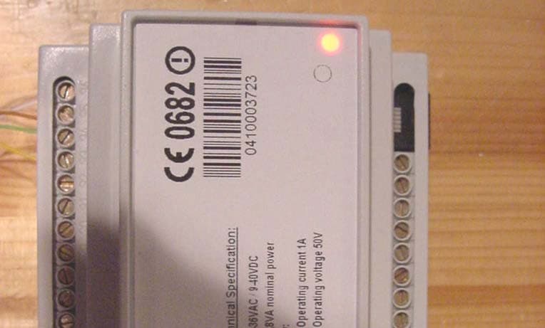
PW3201
May 13, 2004RFID System
Equipment Class
DXX - Part 15 Low Power Communication Device Transmitter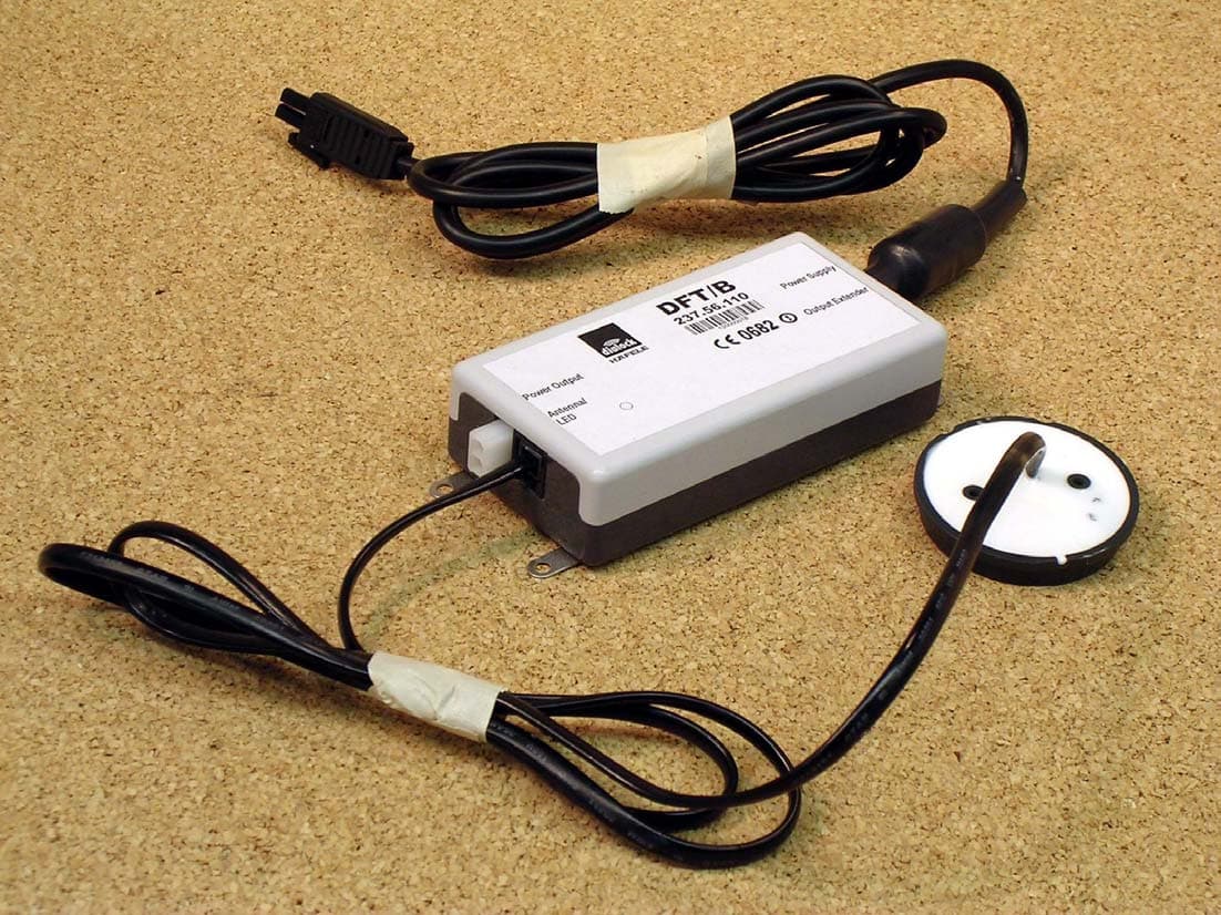
PW3112
Mar 02, 2004Electronic Locking System
Equipment Class
DCD - Part 15 Low Power Transmitter Below 1705 kHz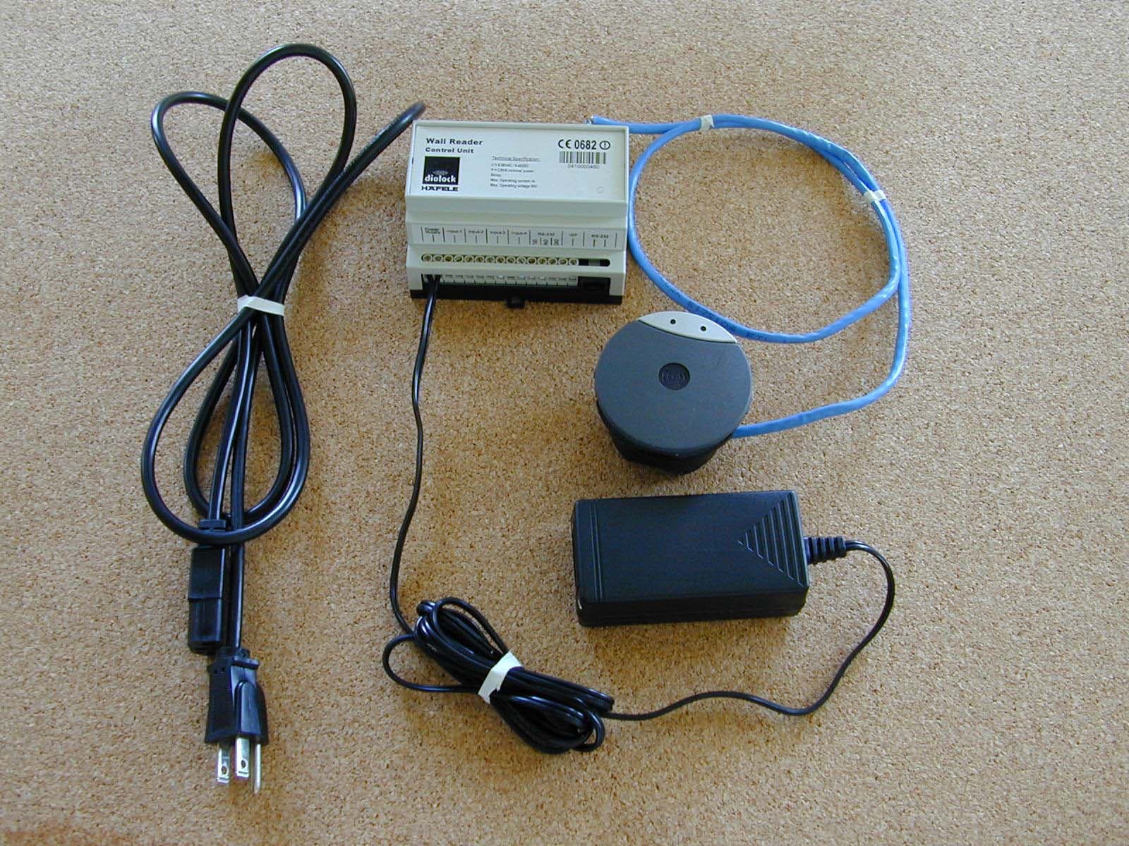
PW3110
Jun 11, 2003RFID System
Equipment Class
DCD - Part 15 Low Power Transmitter Below 1705 kHz
PW3111
Jun 10, 2003RFID System
Equipment Class
DXX - Part 15 Low Power Communication Device Transmitter
PW3104
Nov 26, 2002Wall-mounted door and lock control
Equipment Class
DCD - Part 15 Low Power Transmitter Below 1705 kHz