PW3104Wall-mounted door and lock control
Hafele America Co.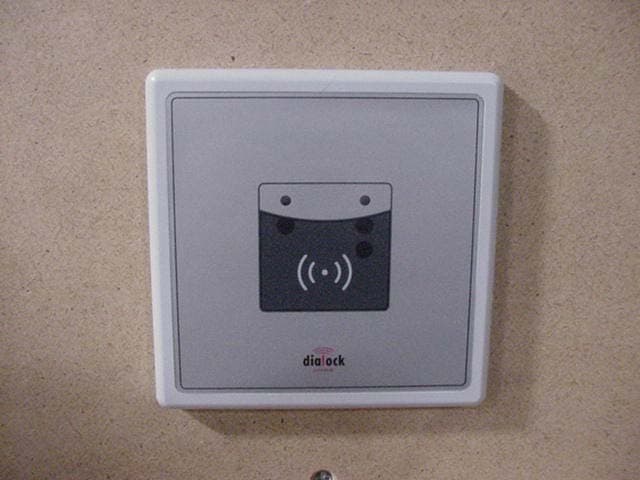
Click to zoom
Application Details
- Equipment Class
- DCD - Part 15 Low Power Transmitter Below 1705 kHz
- Date of Grant
- Nov 26, 2002
- Application Purpose
- Original Equipment
- Date of Application
- Nov 26, 2002
- Equipment Note
- Wall-mounted door and lock control
- Frequency Range
- 0.13400000 - 0.13400000
- Company
- Hafele America Co.
- Country
- United States
Documents & Files
Document Text
Text extracted from the exhibit documents filed with the FCC. Open a document above to read the original.
Users Manual
Wall Terminal Mounting instructions Mounting instructions engl.15 Technical information All wall terminals are supplied in the basic method of operation. With this method of operation, electronic keys are given access authorisations directly at the wall terminal with a special programming key stick (green). Up to 100 electronic keys can be allocated per wall terminal. With a clearing key stick (red), the access authorisations of an authorised electronic key can be withdrawn directly at the wall terminal. If a different method of operation needs to be chosen, please contact your Dialock sales office. Technical data Voltage supply10 - 12 VDC, 8 - 10 VAC Continuous current intake<200 mA Peak current intake250 - 400 mA, depending on number of relays Number of relays1 - 3 Contact load relay Voltage on contactmax. 60 VDC, max. 125 VAC Current on contactmax. 2 A, (short term) Contact ratingmax. 30 W, max. 60 VA Continuous currentmax. 1 A Data retention in case of power cut 10 years for external sector for internal sector Protection level Reader moduleIP 68IP 54 Control electronics moduleIP 66IP 66 Temperature-operating range Reader module-20 - 80 °C0 - 60 °C Control electronics module0 - 60 °C0 - 60 °C relative air humidity (non condensating) 0 - 95 %0 - 95 % Mounting instructions 16engl. Range of application Wall terminals control electric door openers and motor locks for: lexternal or internal doors or: lautomatic roller shutters lbarriers appliances and installations, such as goods dispensers or sun beds can also be monitored via wall terminals. Important characteristics: lsuitable for surface- and flush fitted installation lcan be used as cash terminal lcan be connected to a central unit (PC) via online adapter Supply schedule The configuration supplied, consists of: lreader module with approx. 2.5m long, round, flat band cable and plug for connection to the control electronics module lfront foil to apply onto the reader module lspacer plate for the surface installation of the reader module lcontrol electronics module with one relay (optionally up to 3) lscrew fixings for the casing of the control electronics module lPG-9-screw fixing for connecting the flat band cable to the control electronics module lfeeder implement to connect cables to the control electronics module lspare plug for the flat band cable Mounting instructions engl.17 Installation The following steps are necessary for the installation: linstall the reader module linstall the control electronics module lelectrical installation 654 3 10 7 8 9 1 2 1flat band cable (round, shielded) 2reader module 3element to be switched (appliance) 4power supply for element to be switched (appliance) 5distributor 6control electronics module 7power supply for control electronics module 8conductor 9interface cable (optional) 10online-adapter (optional) During the planning phase, the following installation measures need to be considered: linternal or external installation of the modules lexact location for the modules to be installed, considering the position of the elements to be switched (i.e. door lock, barrier) lsurface- or flush fitted installation of the modules lconnection of the wall terminals to a central unit (PC) via online- adapter Mounting instructions 18engl. Install the reader module Preparations: ldrill a hole into the wall for the connecting cable between the reader module and the control electronics module. Lay a protective pipe with an internal diameter of at least 12 mm or a cable channel. lflush fitted installation: install a flush fitted container with a diameter of 70 mm and a minimum depth of 60 mm. lsurface installation: drill a 25 mm diameter hole and minimum 48 mm depth for the PG-9-screw fixing. 1 2 3 min. 48 4 5 min. 25 1 2 3 min. 60 4 70 Flush fitted installation (left) and surface installation (right) of the reader module 1protective pipe (internal diameter min. 12 mm) 2cable (diameter = 8 to 9 mm, length = 2,5 m) 3flush fitted container, resp. drilling for PG-9-screw fixing 4reader module 5spacer plate 1. for flush fitted installation: drill a 12 mm diameter hole in the centre of the flush fitted container. 2. for flush fitted installation: remove the spacer plate of the reader module. Mounting instructions engl.19 1spacer plate 2reader module 310-mm-hole 4front foil 3. For installation on brick work: ÿdrill holes for 6 mm dowels into the wall to fix the reader module. ÿfix the reader module with 4 Hospa screws, 4x50 mm. Make sure, that the 10 mm hole is at the bottom and that the screws do not protrude over the countersinkings. 4. For installation on metal: ÿdrill four holes for an M4 thread. ÿcut the thread ÿfix the reader module with four countersunk screws. Make sure, that the 10 mm hole is at the bottom and that the screws do not protrude over the countersinkings. 5. guide the free end of the cable through the hole in the brick work to the control electronics module. If the plug does not fit through the hole in the brick work: ÿcut off the plug. ÿloosen the PG-9-screw fixing and strip it off the cable. Mounting instructions 20engl. ÿguide the free end of the cable through the hole to the control electronics module. ÿcut the cable to length. ÿre-fit the PG-9-screw fixing to the cable. ÿguide the flat band cable through the aperture in the spare plug, such that the arrow on the plug is on the same side as the red marking of the flat band cable (polarity!) ÿsqueeze the spare plug shut with water pump pliers or with special squeezing pliers. 6. Apply the front foil onto the reader module. Line up the cut outs of the front foil with the apertures in the reader module for coverage. Mounting instructions engl.21 Install the control electronics module Conditions: lcables and power supply for all appliances to be connected have been laid lfor flush fitted installation: a sufficiently large drilling has been prepared 1 2 3 4 3 4 2 5 1 Flush fitted installation (left) and surface installation (right) of the control elec…
Text truncated - open the document above for the full version.
Block Diagram
BLOCK-DIAGRAM Dialock Wall Terminal monitoring-LEDs red/green IR-interface transponder- interface 80C51 prozessor system I/O RTC RAM buffered linear voltage regulator RS-232 interface transformer 8 - 9 VAC 4 VA 110VAC 50/60Hz 4 x relay output (COM,NC,NO) 2 x TTL-output 4 x TTL-input online operating 16 standard length 2,5m transponder interface: TIRIS: 134,2 kHz (antenna frequency) 4,00 MHz (resonator frequency) or LEGIC: 13,56 MHz (antenna frequency) 13,56 MHz (crystal frequency) C.Meier 26.02.02 SPX 9600 Baud direct signals Reader Unit Control Unit to Output Extender (placement variation) battery crystal 11,0592MHz N.a.: Since the interfaces are synchroneous the frequencies are not predictable but less than 1MHz.. N.a. N.a. N.a. N.a. N.a. N.a. N.a. N.a. 9600 Baud
External Photos
Wall Terminal STS-13 reader Wall Mount Front Wall Terminal STS-13 reader Wall Mount Rear ID Reader SCS-24B external
ID Label/Location Info
This device complies with part 15 of the FCC rules. Operation is subject to the following two conditions: (1) This device may not cause harmful interference, and (2) This device must accept any interference received, including interference that many cause undesired operation. FCC ID: PW3104
Internal Photos
STS-13 Reader PCB STS-13 Reader PCB Wall Terminal ID Reader SCS-24b Wall Terminal ID reader SCS-24b
Operational Description
1.0 Operational Description The EUT (equipment under test) is a wall terminal that can open and close doors and motor locks. The device operates by using an intentional radio frequency (RF) to a pre- programmed transponder key. The transponder keys are passive devices that take the energy from the magnetic field of the EUT then sends the information stored within it to the EUT. The device operates continuously at an intention radiation frequency of 134Khz. The transmitting antenna is not removable.
Test Report
Underwriters Laboratories Inc. 1285 Walt Whitman Road Melville, New York 11747-3081 (631) 271-6200 Report of Measurements of Electromagnetic Compatibility Testing Test Report File No. : NC4085 Date of issue: 10/22/2002 Applicant : Hafele Model / Serial No. : Central Locking Wall Terminal / Product Type : Access Controller Power Supply : 120Vac, 60Hz to 12VDC converter Manufacturer : Same As Applicant License holder : Same As Applicant Address : 3901 Cheyenne Drive : Archdale, NC 27263 Test Type : Compliance Investigation Manufacturer’s Specification Test Project Number : 00ME10760 References(s) FCC ID: PW3104 Underwriters Laboratories Inc. authorizes the above-named company to reproduce this Report provided it is reproduced in its entirety. Underwriters Laboratories Inc. reports apply only to the specific samples tested under stated test conditions. It is the manufacturer's responsibility to assure that additional production units of this model are manufactured with identical electrical and mechanical components. Underwriters Laboratories Inc. shall have no liability for any deductions, inferences or generalizations drawn by the client or others from Underwriters Laboratories Inc. issued reports. This report is the confidential property of the client. As a mutual protection to our clients, the public and ourselves, extracts from the test report shall not be reproduced except in full without our written approval. This report shall not be used by the client to claim product endorsement by NVLAP or any agency of the US government. Page 1 of 19 Underwriters Laboratories Inc. 1285 Walt Whitman Rd. Melville, New York 11747 USA Tel.: 631 271-6200 Fax: 631 439-6095 Rev. No 1.0 File Number: NC4085 Issued: 10/22/2002 Project Number: 00ME10760 Model Number: Central Locking Wall Terminal FCC ID: PW3104 Report Directory 1.0 G E N E R A L - Product Description.........................................................................................3 1.1 Device Configuration During Test............................................................................................................3 1.2 Deviations from ANSI C63.4....................................................................................................................3 1.3 Device Modifications Necessary for Compliance..................................................................................... 3 2.0 EMISSIONS TEST REGULATIONS........................................................................................4 2.1 EUT OPERATION MODE - EMISSIONS TESTS..................................................................................4 2.1.1 Conducted Emissions Tests................................................................................................................5 2.1.2 Radiated Emissions Test (10 Meter Semi-Anechoic Chamber).........................................................9 3.0 Sample Calculations..................................................................................................................18 4.0 SUMMARY:...............................................................................................................................19 Page 2 of 19 Underwriters Laboratories Inc. 1285 Walt Whitman Rd. Melville, New York 11747 USA Tel.: 631 271-6200 Fax: 631 439-6095 Rev. No 1.0 File Number: NC4085 Issued: 10/22/2002 Project Number: 00ME10760 Model Number: Central Locking Wall Terminal FCC ID: PW3104 1.0 G E N E R A L - Product Description The EUT (equipment under test) is a wall terminal that can open and close doors and motor locks. The device operates by using an intentional radio frequency (RF) to a pre-programmed transponder key. The transponder keys are passive devices that take the energy from the magnetic field of the EUT then sends the information stored within it to the EUT. The device operates continuously at an intention radiation frequency of 134Khz. The transmitting antenna is not removable. The device does not need to undergo RF-exposure measurements/calculations. Per FCC Part 2.1093(c) this device is not required to undergo test 1.1 Device Configuration During Test The device under test was configured to operate continuously by transmitting the authorization frequency of 134Khz. The device was tested in its normal orientation. All other orientations were examined. The data contained in this report represents the worst-case axis. The device was powered with a Switching mode power supply. The manufacturer is Mean Well, Model number PSU30A-3. Input voltage is 120VAC, 60Hz and the output voltage is 12VDC. "The results contained in this report reflect the results for this particular model and serial number. It is the responsibility of the manufacturer to ensure that all production models meet the intent of the requirements detailed within this report" 1.2 Deviations from ANSI C63.4 Not Applicable 1.3 Device Modifications Necessary for Compliance N/A Environmental conditions in the lab: Range Temperature: 20-25°C Relative Humidity 30 - 60 % Atmospheric pressure 680 - 1060 mbar Page 3 of 19 Underwriters Laboratories Inc. 1285 Walt Whitman Rd. Melville, New York 11747 USA Tel.: 631 271-6200 Fax: 631 439-6095 Rev. No 1.0 File Number: NC4085 Issued: 10/22/2002 Project Number: 00ME10760 Model Number: Central Locking Wall Terminal FCC ID: PW3104 2.0 EMISSIONS TEST REGULATIONS FCC Part 15, Subpart C, 15.109 and 15.209 FCC Part 15, Subpart B, Class B 2.1 EUT OPERATION MODE - EMISSIONS TESTS Standby Test program (H-Pattern) Test program (color bar) Test program (customer specific) Practice operation Normal operation Mode: As per manufacturer’s instructions: Continuous operation Page 4 of 19 Underwriters Laboratories Inc. 1285 Walt Whitman Rd. Melville, New York 11747 USA Tel.: 631 271-6200 Fax: 631 439-6095 Rev. No 1.0 File Number: NC4085 Issued: 10/22/2002 Project Number: 00ME10760 Model Number: Central Locking Wall Terminal FCC ID: PW3104 2.1.1 Conducted Emissions Tests Test Applicable Te…
Text truncated - open the document above for the full version.
Test Setup Photos
Radiated Emissions Test 30 – 1000 MHz Radiated Emissions Test .1 – 30 MHz Conducted Emissions Test .150 – 30 MHz
Contact Information
Applicant
Jeff Ratkus(Lighting Product Manager)
Technical Contact
Underwriters Laboratories Inc.James R Marley
[email protected](919) 549-1408
12 Laboratory Drive · Research Triangle Park, North Carolina · United States
Non-Technical Contact
Underwriters Laboratories Inc.James R Marley
[email protected](919) 549-1408
Test Firm
UL LLCBob Delisi
Technical Specifications
| # | Rule Parts | Frequency Range | Power Output |
|---|---|---|---|
| 1 | 15C | 0.134 MHz - 0.134 MHz | - |
Other Applications from Hafele America Co.
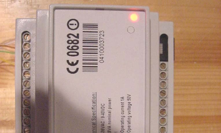
PW3201
May 13, 2004RFID System
Equipment Class
DXX - Part 15 Low Power Communication Device Transmitter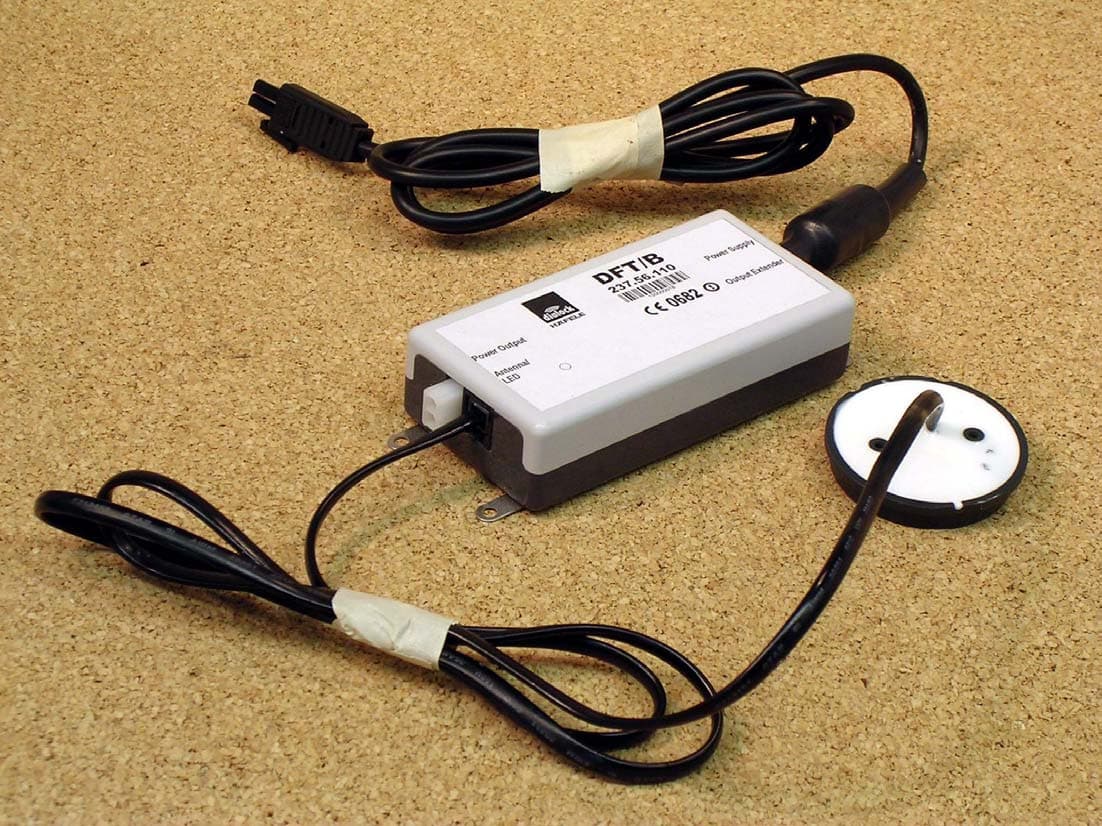
PW3112
Mar 02, 2004Electronic Locking System
Equipment Class
DCD - Part 15 Low Power Transmitter Below 1705 kHz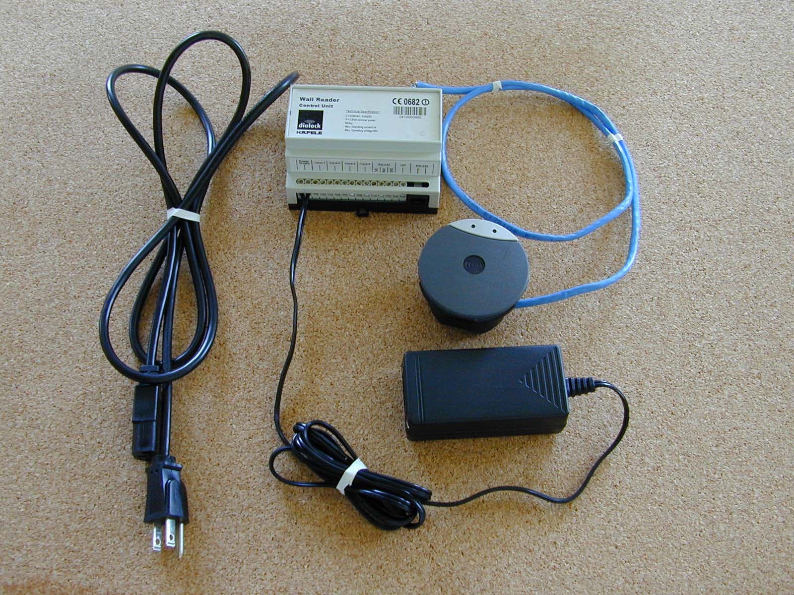
PW3110
Jun 11, 2003RFID System
Equipment Class
DCD - Part 15 Low Power Transmitter Below 1705 kHz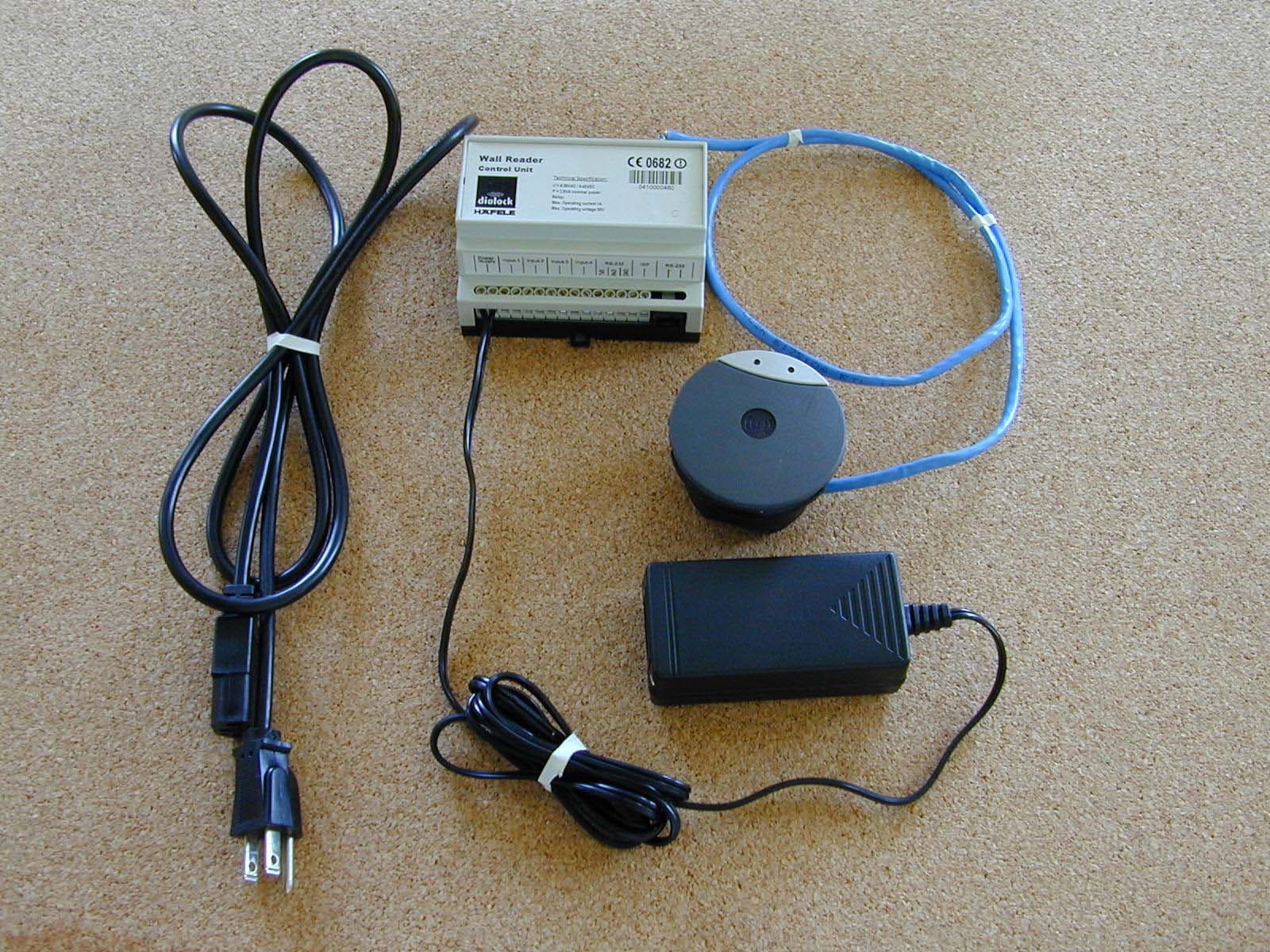
PW3111
Jun 10, 2003RFID System
Equipment Class
DXX - Part 15 Low Power Communication Device Transmitter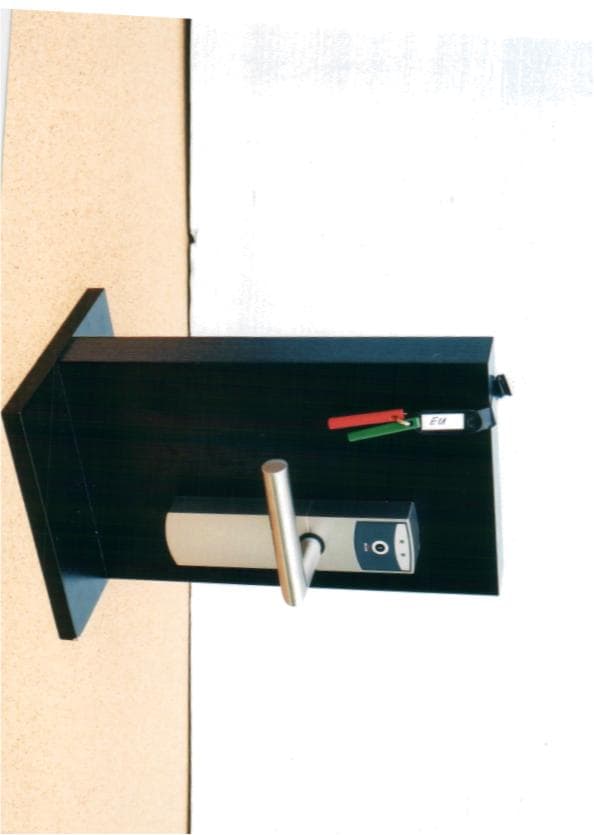
PW3108
Aug 19, 2002Doorknob Entry System
Equipment Class
DCD - Part 15 Low Power Transmitter Below 1705 kHz