PW3112Electronic Locking System
Hafele America Co.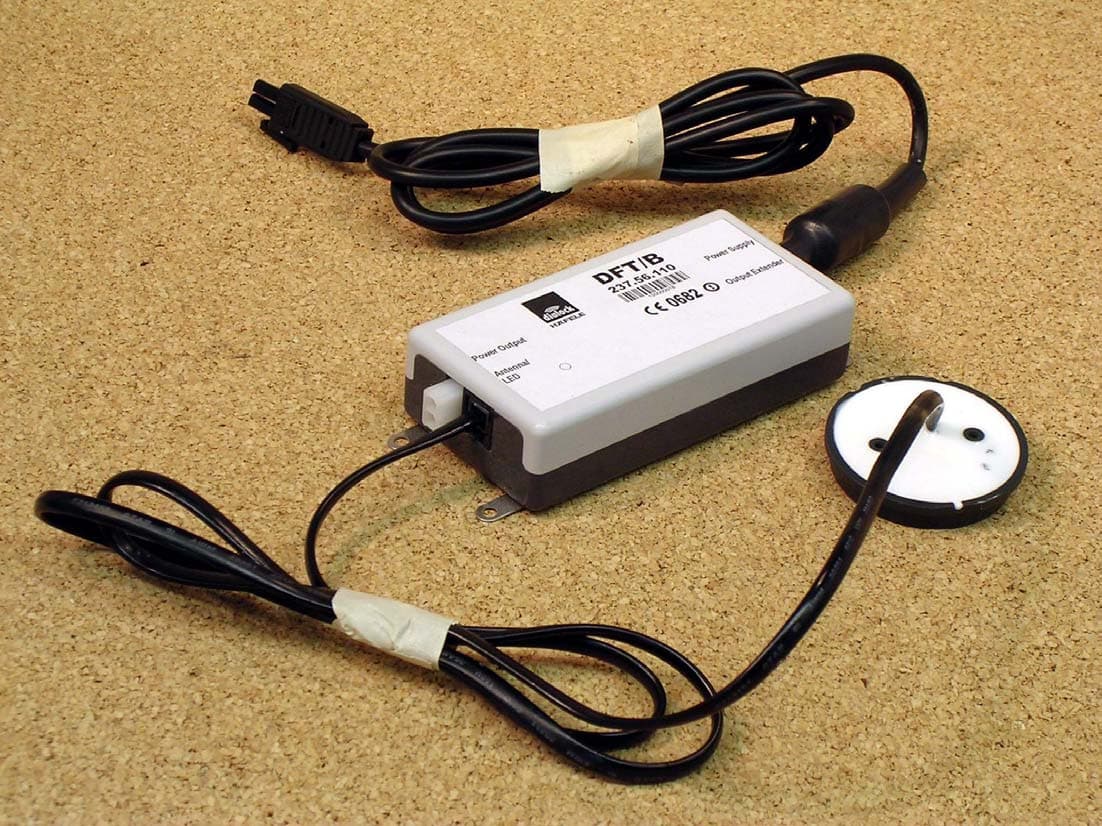
Click to zoom
Application Details
- Equipment Class
- DCD - Part 15 Low Power Transmitter Below 1705 kHz
- Date of Grant
- Mar 02, 2004
- Application Purpose
- Original Equipment
- Date of Application
- Mar 02, 2004
- Equipment Note
- Electronic Locking System
- Frequency Range
- 0.13600000 - 0.13600000
- Company
- Hafele America Co.
- Country
- United States
Documents & Files
Document Text
Text extracted from the exhibit documents filed with the FCC. Open a document above to read the original.
Users Manual
Re: Certification for Hafele DFT\B Transmitter PNs: 237.56.120, 237.56.110 FCC ID: PW3112 IC: 4645A-112 USER'S MANUAL INFORMATION (PRELIMINARY) The User's Manual is in preparation. The following material will be contained in the manual: FCC ID: PW3112 IC: 4645A-112 This device complies with Part 15 of the FCC Rules and with RSS-210 of Industry Canada. Operation is subject to the following two conditions: (1) This device may not cause harmful interference, and (2) This device must accept any interference received, including interference that may cause undesired operation. WARNING: Changes or modifications not expressively approved by the party responsible for compliance could void the user's authority to operate the equipment. The term “IC:” before the radio certification number only signifies that Industry Canada technical specifications were met.
Block Diagram
BLOCK-DIAGRAM Dialock furniture terminal (DFT) Externa lAntenna andLED transponder- interface 80C51 prozessor system I/O voltage regulator RS-485 interface transformer 12VAC 1A 110VAC 50/60Hz Output forelectrica lfurniturelock online operating transponder i nterface: TIRIS: 136,3 kHz (antenna frequency) 4,00 MHz (resonatorfrequency) M.Bürgel22.08.03SPX to OutputExtender crystal 11,0592MHz N.a.: Since the interfaces are synchroneous th efrequencies are not predictable but less than1MHz.. N.a. N.a.N.a. N.a. 9600 Baud OptionalRs485 Internal antenna N.a. Optional
Cover Letter(s)
Re: Certification for Hafele DFT\B Transmitter PNs: 237.56.120, 237.56.110 FCC ID: PW3112 IC: 4645A-112 POWER OF ATTORNEY A letter granting Valdis V. Liepa the Power of Attorney is on file and can be provided when so requested. Re: Certification for Hafele DFT\B Transmitter PNs: 237.56.120, 237.56.110 FCC ID: PW3112 IC: 4645A-112 REQUEST FOR CONFIDENTIALITY Pursuant to 47 CRF 0.459, Hafele America Co. requests that a part of the subject application be held confidential. This comprises Exhibits (5) Schematics (10) Parts List (Part of Exhibit only) Hafele America Co. has spent substantial effort in developing this product and it is one of the first of its kind in industry. Having the subject information easily available to "competition" would negate the advantage they have achieved by developing this product. Not protecting the details of the design will result in financial hardship. If there are any questions regarding this request, please contact me at the above address or call 734-483-4211, fax 734-647-2106 or e-mail [email protected]. Sincerely, Valdis V. Liepa Research Scientist University of Michigan February 17, 2004 Re: Certification for Hafele DFT\B Transmitter PNs: 237.56.120, 237.56.110 FCC ID: PW3112 IC: 4645A-112 STATEMENT OF MODIFICATIONS No EMI changes were made relating to the LF emissions of the device. However, to meet FCC Class B digital emissions, a ferrite bead (Steward #38A2029-0A0) was placed with double turn on each attached i/o cables. The power cable already has an attached ferrite. No ferrite was placed on the external antenna cable (237.56.110 device only). _____________________ Valdis V. Liepa Research Scientist Re: Certification for Hafele DFT\B Transmitter PNs: 237.56.120, 237.56.110 FCC ID: PW3112 IC: 4645A-112 GENERAL PRODUCT INFORMATION The device, for which certification is pursued, has been designed by: Hafele America Co. 3901 Cheyenne Dr., PO Box. 4000 Archdale, NC 27263-4000 Mr. John O’Meara Tel: 914-669-5927 Fax: 914-646-8715 It will be manufactured by: Hafele America Co 3901 Cheyenne Dr., PO Box. 4000 Archdale, NC 27263-4000 Mr. John O’Meara Tel: 914-669-5927 Fax: 914-646-8715 Canadian Contact: Häfele Canada Inc. 5323 John Lucas Drive Burlington, Ontario, L7L 6A8 Canada Martin Häfele, General Manager Tel: ++1 905 336 6608 ext 430 Fax: ++1 905 319 4445 E-mail: [email protected]
Cover Letter(s)
American Telecommunications Certification Body Inc. 6731 Whittier Ave, McLean, VA 22101 December 10, 2003 RE: Hafele America Co. FCC ID: PW3112 I have a few comments on the above referenced Application. EMC Report 1) The device's ports (RS485, power output port, output extender ports, etc.) should have been filled for testing according to ANSI C63.4 6.1.3 & 6.1.4 for a worse case configuration. The final configuration should have included these port filled, or at least the device scanned with and without these ports to determine the effect on the emissions (both digital device and TX emissions). Note that even the DC output cable can create radiation concerns due to differences in filtering (i.e., no ferrite, missing capacitors, etc.) Many of the automotive device you submit are not required to be populated as such since they fall under the exemption of 15.103(a). Given the closest of the margin for the external antenna model which has an additional cable, there may be concern once the missing additional ports are populated. 2) Additionally, it appears that even the models tested do not include some of the optional connections shown in the component placement diagram. It does not appear that worse case samples have been tested. Please explain. 3) Please provide internal photographs underneath the shields of the device. 4) Please confirm the nominal operating frequency. The test report/731 state 136 kHz, however the block diagram from the manufacturer shows an antenna frequency of 134.2 kHz. 5) The limits in table 5.1a and 5.1c are correct for measurements up through 408.9 kHz. However, the limits above this frequency are actually shown in uV/m instead of dBuV/m and therefore affects the results. Please correct. 6) The table at the bottom of page 7 & 9 states digital device emissions are > 20 dB below the limit, however results on the next few pages show otherwise. Please correct. 7) Compliance has been shown to the QP limits for conducted emissions. However several points exceed the average limits. Note that the device must meet with both the peak and average limits. There is QP data that meets the QP limit but exceeds the average limit. Therefore additional average measurements should have also been shown. Timothy R. Johnson Examining Engineer mailto: [email protected] The items indicated above must be submitted before processing can continue on the above referenced application. Failure to provide the requested information may result in application termination. Correspondence should be considered part of the permanent submission and may be viewed from the Internet after a Grant of Equipment Authorization is issued. Please do not respond to this correspondence using the email reply button. In order for your response to be processed expeditiously, you must submit your documents through the AmericanTCB.com website. Also, please note that partial responses increase processing time and should not be submitted. Any questions about the content of this correspondence should be directed to the sender.
Cover Letter(s)
American Telecommunications Certification Body Inc. 6731 Whittier Ave, McLean, VA 22101 March 3, 2004 RE: Hafele America Co. FCC ID: PW3112 I have a few comments on the above referenced Application. EMC Report 1) Some external photographs show 3 ferrites, while other photos show 4, for the same model device. The test report states that ferrites were not placed on the external antenna cables, however some photos appear to show this. Please explain. 2) Please explain how the manufacturer currently plans tol implement the ferrites. Typically the FCC does not allow the end user to install the ferrites, but requires them to be molded into the cables. Are the cables provided? 3) An updated attestation exhibit, including new modifications does not appear to have been provided. Please provide. 4) It appears that the models tested do not include some of the optional connections shown in the component placement diagram (S3 & S5). It does not appear that worse case samples have been tested. Please explain. 5) The limits in table 5.1a and 5.1c are correct for measurements up through 408.9 kHz. However, the limits above this frequency are actually shown in uV/m instead of dBuV/m and therefore affects the results. Please correct. Timothy R. Johnson Examining Engineer mailto: [email protected] The items indicated above must be submitted before processing can continue on the above referenced application. Failure to provide the requested information may result in application termination. Correspondence should be considered part of the permanent submission and may be viewed from the Internet after a Grant of Equipment Authorization is issued. Please do not respond to this correspondence using the email reply button. In order for your response to be processed expeditiously, you must submit your documents through the AmericanTCB.com website. Also, please note that partial responses increase processing time and should not be submitted. Any questions about the content of this correspondence should be directed to the sender. z Page 1March 3, 2004 American Telecommunications Certification Body Inc. 6731 Whittier Ave, McLean, VA 22101
Cover Letter(s)
American Telecommunications Certification Body Inc. 6731 Whittier Ave, McLean, VA 22101 March 3, 2004 RE: Hafele America Co. FCC ID: PW3112 I have a few comments on the above referenced Application. EMC Report 1) Previous attestation letters/test report/internal photographs also included modifications that no longer appear in the new exhibits. Are these old modifications not longer necessary. Please explain and adjust exhibits as necessary. Timothy R. Johnson Examining Engineer mailto: [email protected] The items indicated above must be submitted before processing can continue on the above referenced application. Failure to provide the requested information may result in application termination. Correspondence should be considered part of the permanent submission and may be viewed from the Internet after a Grant of Equipment Authorization is issued. Please do not respond to this correspondence using the email reply button. In order for your response to be processed expeditiously, you must submit your documents through the AmericanTCB.com website. Also, please note that partial responses increase processing time and should not be submitted. Any questions about the content of this correspondence should be directed to the sender. z Page 1March 3, 2004 American Telecommunications Certification Body Inc. 6731 Whittier Ave, McLean, VA 22101
Cover Letter(s)
RE: Hafele America Co. FCC ID: PW3112 The following is in response to comments made on the above application. EMC Report 1) Some external photographs show 3 ferrites, while other photos show 4, for the same model device. The test report states that ferrites were not placed on the external antenna cables, however some photos appear to show this. Please explain. Our apologies, two of the photos were switched during labeling. We have uploaded a revised exhibit. 2) Please explain how the manufacturer currently plans to implement the ferrites. Typically the FCC does not allow the end user to install the ferrites, but requires them to be molded into the cables. Are the cables provided? All cables will be provided by the manufacturer with molded ferrites attached. 3) An updated attestation exhibit, including new modifications does not appear to have been provided. Please provide. The exhibit has now been uploaded. 4) It appears that the models tested do not include some of the optional connections shown in the component placement diagram (S3 & S5). It does not appear that worse case samples have been tested. Please explain. The S3 and S5 components will never be populated for the devices in question. 5) The limits in table 5.1a and 5.1c are correct for measurements up through 408.9 kHz. However, the limits above this frequency are actually shown in uV/m instead of dBuV/m and therefore affects the results. Please correct. The updated tables were mistakenly not included in the test report. A revised test report has been uploaded.
Cover Letter(s)
RE: Hafele America Co. FCC ID: PW3112 The following is in response to comments made on the above application. 1) Previous attestation letters/test report/internal photographs also included modifications that no longer appear in the new exhibits. Are these old modifications no longer necessary? Please explain and adjust exhibits as necessary. The modifications originally made were no longer necessary once the manufacturer elected to use ferrites on the associated cables. Thus, these modifications are no longer part of the application.
External Photos
DUT (with Ext. Antenna) DUT (top) (Ext. Antenna) with Ferrites - FCC Class B DUT (bottom) ( Ext . Antenna) with Ferrites - FCC Class B DUT (top) (Int. Antenna) with Ferrites - FCC Class B DUT (bottom) ( Int . Antenna) with Ferrites - FCC Class B
ID Label/Location Info
Label for Häfele DFT/B Häfele Model: DFT/B FCC ID: PW3112 IC: 4645A-112 This device complies with part 15 of the FCC Rules and with RSS-210 of Industry Canada. Operation is subject to the following two conditions: (1) This device may not cause harmful interference, and (2) this device must accept any interference received, including interference that many cause undesired operation.
Internal Photos
DUT Apart top - Ext. Antenna DUT Apart bottom - Ext. Antenna PCB in Chassis - Ext. Antenna PCB top - Ext. Antenna PCB bottom - Ext. Antenna DUT Apart top - Int. Antenna DUT Apart bottom - Int. Antenna PCB in Chassis - Int. Antenna PCB top - Int. Antenna Close-up RF Sheild
Operational Description
30 Installation and Operating Instructions Dialock Furniture Terminal - status: 10.2003 - 732.29.129 English Area of application The Dialock Furniture Terminal is part of the Dialock electronic locking system. It is the central unit for the electro-mechanical locking of furniture items such as cupboards, drawers, lockers and roller shutters. Performance characteristics • Simple and convenient operation • Use of up to 200 user keysticks • Control of up to 6 FLC lock mechanisms, or with a second 6-fold dis- tributor, up to 11 FLC mechanisms. The opening and closing process is the same for each FLC mechanism (simultaneously locking). • Possibility of controlling other FLC mechanisms by means of the option- al output extender. This allows individual setting of the opening and closing process of each FLC lock mechanism (individually addressable). • Possible locking modes: locking cycle (set by manufacturer) and alter- nating mode. • Selectable locking modes: locking cycle and alternating mode. Basics Locking cycle:when an authorised user keystick is held in front of it, the Dialock Furniture Terminal unlocks the lock mechanism for a certain selectable period. During this time, it is possible to open the item of furni- ture (e.g. a locker). Following this period, the Dialock Furniture Terminal locks the mechanism again automatically. Alternating mode:when an authorised user keystick is held in front of it, the Dialock Furniture Terminal unlocks the lock mechanism. However, the Dialock Furniture Terminal does not close it again until an authorised user keystick is again held in front of it.
Test Report
The University of Michigan Radiation Laboratory 3228 EECS Building Ann Arbor, MI 48109-2122 Tel: (734) 764-0500 Measured Radio Frequency Emissions From Hafele America Transmitter Model DFT/B Report No. 415031-189 February 14 , 2004 Cop y right © 2004 For: Hafele America Co 3901 Cheyenne Drive Archdale, NC 27263 Contact: Rudor Teich Tel: 973-669-8214 Fax: 973-669-5161 Tests supervised by: Measurements made by: Joseph D. Brunett Report approved by: _____________________ Valdis V. Liepa Research Scientist Summary Tests for compliance with FCC Regulations, Part 15, Subpart C, and for compliance with Industry Canada RSS-210, were performed on Hafele America Co transmitter, model DFT/B. This device is subject to Rules and Regulations as a transmitter. In testing completed 19-Nov-03, the device tested in the worst case met the allowed specifications for transmitter radiated emissions by 24.2 dB (see p. 7); digital emissions, Class B, were met by2.9 dB (see p. 7); FCC/CISPR Class B conducted were met by 1.5 dB (see p. 7). 2 1. Introduction Hafele America Co model DFT/B was tested for compliance with FCC Regulations, Part 15, adopted under Docket 87-389, April 18, 1989, and with Industry Canada RSS-210, Issue 5, November, 2001. The tests were performed at the University of Michigan Radiation Laboratory Willow Run Test Range following the procedures described in ANSI C63.4-1992 "Methods of Measurement of Radio-Noise Emissions from Low-Voltage Electrical and Electronic Equipment in the Range of 9 kHz to 40 GHz". The Site description and attenuation characteristics of the Open Site facility are on file with FCC Laboratory, Columbia, Maryland (FCC Reg. No: 91050) and with Industry Canada, Ottawa, ON (File Ref. No: IC 2057). 2. Test Procedures and Equipment Used The pertinent test equipment commonly used in our facility for measurements is listed in Table 2.1 below. The middle column identifies the specific equipment used in these tests. Table 2.1 Test Equipment. Test Instrument Eqpt. Used Manufacturer/Model Spectrum Analyzer (0.1-1500 MHz) Hewlett-Packard, 182T/8558B Spectrum Analyzer (9kHz-22GHz) X Hewlett-Packard 8593A SN: 3107A01358 Spectrum Analyzer (9kHz-26GHz) X Hewlett-Packard 8593E, SN: 3412A01131 Spectrum Analyzer (9kHz-26GHz) Hewlett-Packard 8563E, SN: 3310A01174 Spectrum Analyzer (9kHz-40GHz) Hewlett-Packard 8564E, SN: 3745A01031 Power Meter Hewlett-Packard, 432A Power Meter Anritsu, ML4803A/MP Harmonic Mixer (26-40 GHz) Hewlett-Packard 11970A, SN: 3003A08327 Harmonic Mixer (40-60 GHz) Hewlett-Packard 11970U, SN: 2332A00500 Harmonic Mixer (75-110 GHz) Hewlett-Packard 11970W, SN: 2521A00179 Harmonic Mixer (140-220 GHz) Pacific Millimeter Prod., GMA, SN: 26 S-Band Std. Gain Horn S/A, Model SGH-2.6 C-Band Std. Gain Horn University of Michigan, NRL design XN-Band Std. Gain Horn University of Michigan, NRL design X-Band Std. Gain Horn S/A, Model 12-8.2 X-band horn (8.2- 12.4 GHz) Narda 640 X-band horn (8.2- 12.4 GHz) Scientific Atlanta , 12-8.2, SN: 730 K-band horn (18-26.5 GHz) FXR, Inc., K638KF Ka-band horn (26.5-40 GHz) FXR, Inc., U638A U-band horn (40-60 GHz) Custom Microwave, HO19 W-band horn(75-110 GHz) Custom Microwave, HO10 G-band horn (140-220 GHz) Custom Microwave, HO5R Bicone Antenna (30-250 MHz) X University of Michigan, RLBC-1 Bicone Antenna (200-1000 MHz) X University of Michigan, RLBC-2 Dipole Antenna Set (30-1000 MHz) X University of Michigan, RLDP-1,-2,-3 Dipole Antenna Set (30-1000 MHz) EMCO 2131C, SN: 992 Active Rod Antenna (30 Hz-50 MHz) EMCO 3301B, SN: 3223 Active Loop Antenna (30 Hz-50 MHz) X EMCO 6502, SN:2855 Ridge-horn Antenna (300-5000 MHz) X University of Michigan Amplifier (5-1000 MHz) X Avantek, A11-1, A25-1S Amplifier (5-4500 MHz) X Avantek Amplifier (4.5-13 GHz) Avantek, AFT-12665 Amplifier (6-16 GHz) Trek Amplifier (16-26 GHz) Avantek LISN Box University of Michigan Signal Generator Hewlett-Packard 8657B 3 3. Configurations and Identification of Device Under Test The DUT is an RFID furniture locking system operating at 136.3 kHz. This system consists of a T/R module (including coupling coil antenna) and a "passive" transponder imbedded in a special key. The transponder in the key is considered passive because it uses the energy supplied by the transmitter coil to operate its micro and, hence, is not subject to the regulations. Power is supplied from a switching power supply provided by the manufacturer. The DUT was designed and manufactured by Hafele America Co., 3901 Cheyenne Drive, Archdale, NC 27263. It is identified as: Hafele America Co. Transmitter Model: DFT/B PN(s): 237.56.120 (int. antenna) and 237.56.110 (ext. antenna) FCC ID: PW3112 IC: 4645A-112 3.1 EMI Relevant Modifications No EMI changes were made relating to the LF emissions of the device. However, to meet FCC Class B digital emissions, a ferrite bead (Steward #38A2029-0A0) was placed with double turn on each attached i/o cables. The power cable already has an attached ferrite. No ferrite was placed on the external antenna cable (237.56.110 device only). 4. Emission Limits 4.1 Radiated Emission Limits The DUT tested falls under the category of an Intentional Radiators and the Digital Devices, subject to Subpart C, Section 15.209; and Subpart B, Section 15.109 (transmitter generated signals excluded); and Subpart A, Section 15.33. The applicable testing frequencies with corresponding emission limits are given in Tables 4.1 and 4.2 below. As a digital device, it is exempt. Table 4.1. Radiated Emission Limits (FCC: 15.205, 15.35; IC: RSS-210 (6.2.2(r), 6.3)). (Transmitter) Frequency (MHz) Fundamental and Spurious* (μV/m) 0.009-0.490 0.490-1.705 2400/F(kHz), 300m 24,000/F(kHz), 30m 0.090-0.110 0.49-0.51 Restricted Bands * Harmonics must be below the fundamental. For extrapolation to other distances, see Section 6.6. 4 Table 4.2. Radiated Emission Limits (FCC: 15.33, 15.35, 15.109; IC: RSS-210, 6.2.2(r)). (Digital Class B) Freq. (MHz) E lim (3m) μV/m E lim dB(μV/m) 30-88 100 40.0 88-216 150 43.5 216-96…
Text truncated - open the document above for the full version.
Test Setup Photos
D UT on OATS (LF) - External Antenna (NOTE: Was re-tested with a dditional cables and ferrites at a later date - no photo avaliable) D UT on OATS (LF) (close-up) - External Antenna (NOTE: Was r e-tested with additional cables and ferrites at a later date - no photo a valiable) D UT on OATS (LF) - Internal Antenna (NOTE: Was re-tested with a dditional cables and ferrites at a later date - no photo avaliable) D UT on OATS (LF) (close-up) - Internal Antenna (NOTE: Was r e-tested with additional cables and ferrites at a later date - no photo a valiable)
Contact Information
Applicant
Jeff Ratkus(Lighting Product Manager)
Technical Contact
University of Michigan/EECSValdis V Liepa
[email protected]734-483-4211
1301 Beal Ave. · Ann Arbor, Michigan · United States
Non-Technical Contact
University of Michigan/EECSValdis V Liepa
[email protected]734-483-4211
Test Firm
University of MichiganValdis Liepa
Technical Specifications
| # | Rule Parts | Frequency Range | Power Output |
|---|---|---|---|
| 1 | 15C | 0.136 MHz - 0.136 MHz | - |
Other Applications from Hafele America Co.
PW3201
May 13, 2004RFID System
Equipment Class
DXX - Part 15 Low Power Communication Device Transmitter
PW3110
Jun 11, 2003RFID System
Equipment Class
DCD - Part 15 Low Power Transmitter Below 1705 kHz
PW3111
Jun 10, 2003RFID System
Equipment Class
DXX - Part 15 Low Power Communication Device Transmitter
PW3104
Nov 26, 2002Wall-mounted door and lock control
Equipment Class
DCD - Part 15 Low Power Transmitter Below 1705 kHz
PW3108
Aug 19, 2002Doorknob Entry System
Equipment Class
DCD - Part 15 Low Power Transmitter Below 1705 kHz