PW3201RFID System
Hafele America Co.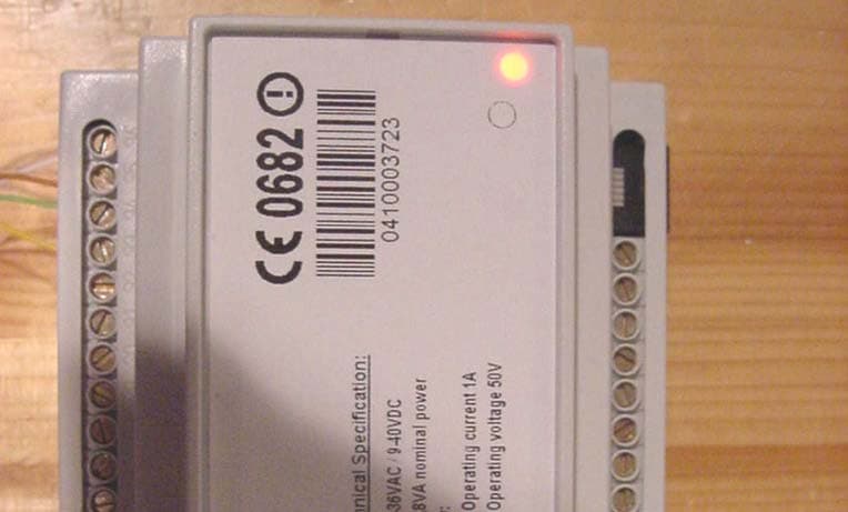
Click to zoom
Application Details
- Equipment Class
- DXX - Part 15 Low Power Communication Device Transmitter
- Date of Grant
- May 13, 2004
- Application Purpose
- Original Equipment
- Date of Application
- May 13, 2004
- Equipment Note
- RFID System
- Frequency Range
- 13.56000000 - 13.56000000
- Company
- Hafele America Co.
- Country
- United States
Documents & Files
Document Text
Text extracted from the exhibit documents filed with the FCC. Open a document above to read the original.
Users Manual
Mounting and Operating Instructions (Simple Programming) Wall Terminal 2000 V.7 Art. No. Model Trans. Format Art. No. Model Trans. Format 917.01.101 Int., 1 Relay TI-RFid 917.21.101 Int., 1 Relay Legic 917.01.104 Int., 4 Relays TI-RFid 917.21.104 Int., 4 Relays Legic Art.No..: 732.29.125, published: 10/2003 2 Contents Components supplied............................................................................3 Area of use............................................................................................3 Features................................................................................................3 Installation instructions..........................................................................4 Start-up................................................................................................11 Instructions for use...............................................................................12 Operation.............................................................................................13 RESET.................................................................................................13 FAQs...................................................................................................14 Technical Data......................................................................................15 Notes...................................................................................................16 3 Components Supplied • Reader unit (1) • Control unit (2) • Installation frame (3) • These instructions Area of Use The wall terminal is part of the Dialock electronic locking systems. It is an access-control system for outdoor and indoor use and can be used for a variety of purposes such as: • Opening and closing doors by triggering electric door openers, motor locks, automatic doors etc. • Triggering electrical equipment (e.g. roller shutters, parking garage barriers, furniture locks, lighting, alarm and video-surveillance systems). Features • Fully compatible with the Dialock system • Macro-programmable • Simple and convenient configuration via infra-red interface • Possible extension of function through special firmware • Separate reader and control units • All the operating modes of the Dialock system • Technology of reader unit: LEGIC and TI-RFid 4 Installation instructions Safety Note: Before beginning installation, ensure that the power supply is switched off. The installation work should be done by a qualified electrician only, as complex wiring is required. Unsuitable tools may cause damage to the wall terminal. Please note that the wall terminal is intended only for switching electrical equipment with max. 1 A constant current and 2 A short-time current. Incorrect or incomplete installation may cause permanent damage to the system. Installation requirement For installation, first determine suitable positions and locations for the reader and control units. This must take into account the equipment being operated (e.g. door lock, barrier etc.). In addition, the recessed socket (fig. 4) for the reader unit and the cable must be installed as shown in the circuit diagram (fig. 5) Installation The following operations are required: • Installation of reader unit • Installation of control unit • Electrical installation Installation of required cable work. Before installing, always remember to switch the power off. For the installation of the electrical connections, observe the following connection diagrams. 5 1. Control unit 2. Reader unit 3. Equipment being switched (door, barrier) 4. Power supply for equipment being switched 5. Distributor 6. External CPU (e.g. PC) (optional) 7. Power supply for contro l and reader units Model No.: DTS120250U/AC6-AMP-SZ Art.No.: 917.93.005 6 Example: electrical connection of an electrical strike 1. Power supply Model No.: DTS120250U/AC6-AMP-SZ Art.No.: 917.93.005 2. Electrical strike 3. Control unit 7 The connection between the reader and the control units can be made using a standard 4-conductor cable. We recommend using a standard electrical cable J-Y (St) Y 2 x 2 x 0.8 with a maximum distance of 100 meters. When installing several wall readers, ensure that the distance between the reader units is at least 25 cm (fig. 7). If the distance is too small, the HF fields may overlap. This may cause the transponder media to not be reliably detected. Reader unit A +5V B GND C RS485A D RS485B Table 1 8 Control Unit Model No.: DTS120250U/AC6-AMP-SZ Art.No.: 917.93.005 9 Mounting the reader unit - Screw the frame of the reader unit into the desired recessed socket - Remove the rear cover - Connect wires as shown in connection plan in table 1 page 7 - Push cable into cable comb - Replace cover and screw into place - Place the reader unit in the frame and allow it to click into position 10 - To disassemble, push a screwdriver into the slot and pry the unit out as shown. Mounting the control unit The control unit may be damaged by use of unsuitable tools. - The distance between the control and reader units may be up to 100 meters. - Mount the control unit on a standard rail (top-hat rail) in accordance with DIN EN 50022. - Connect the wires as stated in table 2 page 8 - If necessary, connect a recovery diode (100V) on the equipment being switched (door opener). The connection should be between common (on the load side) and ground. 11 Start-up The wall terminal is supplied in the “simple programming mode” of operation. Only this mode is described in these instructions. Other operating modes are possible only after consultation with the Dialock sales office. Ensure that unauthorized persons do not misuse the user keys. Keep the programming ADD and DELETE keys in a safe place, as these are used for authorizing user keys. At first start-up, the programming ADD (green) and DELETE (red) keys must be assigned as follows: This operation is only possible directly after applying the supply power to the control unit. 1. Keep the green …
Text truncated - open the document above for the full version.
Cover Letter(s)
CONFIDENTIALITY REQUEST Federal Communication Commission Equipment Authorization Division, Application Processing Branch 7435 Oakland Mills Road Columbia, MD 21048 May 6, 2004 TO WHOM IT MAY CONCERN Pursuant to Paragraphs §0.457 and 0.459 of the Commission’s Rules (47 C.F.R.) and Section §552(b)(4) of the Freedom of Information Act, Hafele America Co. requests confidentiality for the following products: FCC ID Number Product Title/Model PW3201 Wall Terminal ISO (WT ISO) For the product stated above, we request that the following information be held confidential: 1. Circuit diagrams, BOM, and PCBs submitted as Equipment Authorization Electronic Filing attachment: "schematics”. 2. Block diagram submitted as Equipment Authorization Electronic Filing attachment: “blockdiagram”. 3. Operational description submitted as Equipment Authorization Electronic Filing attachment: “operational description” The above exhibits contain Hafele America Co. trade secrets and proprietary information that could be of benefit to our competitors regarding the design of our mobile handset. This material is not customarily available to the general public and we request that it be withheld from public inspection. If you have any questions, please feel free to contact me at the address shown below. Sincerely, (signed) Name: Jeffery R. Ratkus Company: Hafele America Co. Address: 3901 Cheyenne Drive Archdale, NC 27263 USA Phone: +1 336-434-2322 ext. 258 Email: [email protected]
External Photos
CETECOM ICT Services GmbH Test report no.: 2-3497-01-04/04Date: 2004-05-04Page 31 (47) Photograph No.: 02 CETECOM ICT Services GmbH Test report no.: 2-3497-01-04/04Date: 2004-05-04Page 32 (47) Photograph No.: 03 CETECOM ICT Services GmbH Test report no.: 2-3497-01-04/04Date: 2004-05-04Page 33 (47) Photograph no.: 04
Internal Photos
CETECOM ICT Services GmbH Test report no.: 2-3497-01-04/04Date: 2004-05-04Page 34 (47) Photograph No.: 05 CETECOM ICT Services GmbH Test report no.: 2-3497-01-04/04Date: 2004-05-04Page 35 (47) Photograph No.: 06 CETECOM ICT Services GmbH Test report no.: 2-3497-01-04/04Date: 2004-05-04Page 36 (47) Photograph No.: 07 CETECOM ICT Services GmbH Test report no.: 2-3497-01-04/04Date: 2004-05-04Page 37 (47) Photograph No.: 08 CETECOM ICT Services GmbH Test report no.: 2-3497-01-04/04Date: 2004-05-04Page 38 (47) Photograph No.: 09 CETECOM ICT Services GmbH Test report no.: 2-3497-01-04/04Date: 2004-05-04Page 39 (47) Photograph No.: 10 CETECOM ICT Services GmbH Test report no.: 2-3497-01-04/04Date: 2004-05-04Page 40 (47) Photograph No.: 11 CETECOM ICT Services GmbH Test report no.: 2-3497-01-04/04Date: 2004-05-04Page 41 (47) Photograph No.: 12
Operational Description
Operational Description Wallterminal WT2000 ISO Tagit The Wallterminal WT2000 consists of the two components control unit and reader unit. The control unit is usually mounted in a save area inside the building, maybe at an electrical control cabinet. The reader unit is connected to the reader unit using a normal four-pole cable and is mounted outside the building, maybe beside the door. The control unit controls the reader unit using a RS485 interface. All inputs and outputs are on the control unit. The reader unit only sets the two status LEDs and controls the transponder interface. All transponder datas are transmitted directly to the control unit for interpretation. The RFID circuit at the reader unit is based on the Texas Instruments S6700 Multi Protocol Transceiver IC RI-R6C-001A. Please see the attached data sheets for details. 1 June í02Appendix C. Register Definition 11-07-21-001 June 2002 HF Reader System Series 6000 S6700 Multi Protocol Transceiver IC RI-R6C-001A Reference Guide A TEXAS INSTRUMENTS TECHNOLOGY 7 June í02Chapter 1. Introduction 1.1General This document provides information about the S6700 Multi Protocol Transceiver IC. It describes the integrated circuit and how to implement it. 1.2System Description The HF Reader System Series 6000 works at a frequency of 13.56 MHz. It comprises a reader, antenna and transponder (for example: smart label) and is used for wire- less identification. The system works according the ìreader talks firstî principle which means that the transponder keeps quiet until the reader sends a request to it. The reader can rapidly and simultaneously identify numerous transponders in the antennaís field. It can write data to and read data from the transponders; either in addressed mode by using the factory programmed read only number, or in general mode to all of the transpond- ers in its field. The read/write capability of the transponder allows users to update the data stored in the transponders memory anywhere along its movements. 1.3Product Description The S6700 Multi Protocol Transceiver IC opens a rapid path for the development of a broad range of 13.56 MHz RFID readers. It provides the receive/transmit functions required to communicate with a variety of transponders that operate in the 13.56 MHz ISM band. A transmit encoder converts the transmitted data stream into the se- lected protocol; protocol selection is done in the header of the transmitted data string. The transmitter can provide up to 200 mW of RF power to a matched 50 Ω load with a 5 V power supply. Higher output power can be obtained by an external amplifier. The receive decoder converts the signals from the RF receiver into a simple data string. The digital interface provides on-chip data encoding and recovery, thereby minimiz- ing the software design efforts for the end user. Communication with the circuit is achieved by means of a three wire serial link. Figure 1: S6700 Multi Protocol Transceiver IC (RI-R6C-001A) 1.4Communications Protocols The Transceiver IC can handle different RF protocols as follows: 1. Tag-it protocol. 2. ISO / IEC 15693-2 [2]. 3. ISO / IEC 14443-2 (Type A). 4. Direct mode where data can be passed directly thru to a transponder; using the correct modulation, timing, and command structure. 10 S6700 Multi-Protocol Transceiver IC - Reference GuideJune í02 2.1Functional Description A simplified block diagram of the Transceiver IC is shown in Figure 4, the different electronic parts of the IC are described in sections 2.1.1 to 2.1.6. Figure 4: Simplified Block Diagram 2.1.1Power Supply The Transceiver IC requires a nominal 5 volts external power supply. Operation is guaranteed between 3 Volts and 5.5 Volts. The current drain depends on the anten- na impedance and the output matching network configuration. We strongly recom- mended that you use a well regulated supply as power supply ripple and noise will severely degrade the overall system performance. 2.1.2Transmitter The output transistor is a low Ron MOSFET. The drain is directly accessible on the TX_OUT pin. A recommended application schematic optimized to drive a resistive fifty ohms antenna with a five volts power supply is shown in Appendix A. A simple resonant circuit or/and a simple matching network can be connected to the output to reduce harmonic suppression and enhance the general performance. 100% modulation is achieved by means of gating the square wave drive of the output transistor. 423/484/848 kHz Linear PA Lowpass Filter Din Dout SCLOCK Transmitt Decoder Mode Register Modulation dept / out Return loss better 20dB Receive Decoder Oscillator 13.56MHz RX input Vcc Gnd M_ERR Rectifier 11 June í02Chapter 2. Transceiver IC Description The ten percent modulation depth is obtained by means of switching a resistor in se- ries with the output transistor source connection. Increasing the value of this resistor further increases the modulation depth. The transmit encoder converts the data into the selected RF Protocol to be trans- ferred. The communications speed varies from 5 to 120 kbaud and must be at least the speed of the selected transponder protocol. An input buffer is implemented in or- der to have a sufficient number of bits available for the RF transmission. 2.1.3Receiver The receiver input is typically connected to the antenna through an external resistor. The modulation from the tag is then recovered by means of a diode envelope detec- tor. The receiver decoder issues the received data directly to the controller in binary data format. The communication speed and RF protocol is defined by the selected mode. Start, stop and errors in the received data string are detected and indicated at the output. 2.1.4Reference Clock and Internal Oscillator The reference clock can be obtained externally by applying a suitable clock signal to the XTAL2 pin. A sine wave centered at VCC/2 or a CMOS logic compatible signal is an acceptable external system clock. The built-in reference oscillator will work ei- …
Text truncated - open the document above for the full version.
Test Report
CETECOM ICT Services GmbH Radio Satellite Communication Untertürkheimer Straße 6-10 . D-66117 Saarbrücken Telefon: +49 (0)681 598-0 Telefax: -9075 Testreport No.: 2-3497-01-04/04 This test report consist of 47 PagesPage 1 (47) Recognized by the Federal Communications Commission Anechoic chamber registration no.: 90462 (FCC) Anechoic chamber registration no.: 3463 (IC) TCB ID: DE 0001 Accredited by the German Accreditation Council DAR–Registration Number TTI–P–G 081/94-D0 Independent ETSI compliance test house ETSI Accredited Bluetooth™ Test Facility (BQTF) Test report no.: 2-3497-01-04/04 FCC Part 15.225 WT-2000 ISO Tagit FCC ID: PW3201 CETECOM – ICT Services GmbH Untertürkheimerstr. 6-10 66117 Saarbrücken, Germany Telephone: + 49 (0) 681 / 598-0 Fax: + 49 (0) 681 / 598-9075 BLUETOOTH is a trademark owned by Bluetooth SIG, Inc. and licensed to CETECOM CETECOM ICT Services GmbH Test report no.: 2-3497-01-04/04Date: 2004-05-04Page 2 (47) Table of contents 1 General information 1.1 Notes 1.2 Testing laboratory 1.3 Details of applicant 1.4 Application details 1.5 Test item 1.6 Test Set-up 1.7 Test specifications 2 Technical test 2.1 Summary of test results 2.2 Test report CETECOM ICT Services GmbH Test report no.: 2-3497-01-04/04Date: 2004-05-04Page 3 (47) 1 General information 1.1 Notes The test results of this test report relate exclusively to the test item specified in 1.5. The CETECOM ICT Services GmbH does not assume responsibility for any conclusions and generalisations drawn from the test results with regard to other specimens or samples of the type of the equipment represented by the test item. The test report may only be reproduced or published in full. Reproduction or publication of extracts from the report requires the prior written approval of the CETECOM ICT Services GmbH. Test laboratory manager: 2004-05-04RSC - 8431Gillmann D. DateSectionNameSignature Technical responsibility for area of testing: 2004-05-04RSC - 8412Hausknecht D. DateSectionNameSignature CETECOM ICT Services GmbH Test report no.: 2-3497-01-04/04Date: 2004-05-04Page 4 (47) 1.2 Testing laboratory CETECOM ICT Services GmbH Untertürkheimer Straße 6 - 10 66117 Saarbrücken Germany Telephone: + 49 681 598 - 0 Telefax : + 49 681 598 - 9075 E-mail: [email protected] Internet: www.cetecom-ict.de Accredited testing laboratory Accredited by: Regulierungsbehörde für Telekommunikation und Post (RegTP) Listed by: Federal Communications Commission (FCC) AuthorityIdentification/Registration No. RegTPTTI-P-G 081/94-D0 FCC90462 1.3Details of applicant Name :Sphinx Electronics GmbH & Co KG Street :Tullastr. 3 City :79341 Kenzingen Country :Germany Telephone:+49 7644 922857 Telex :+49 7644 922891 E-mail :[email protected] Contact person: Name : Mr. Clemens Meier Telephone:+49 7644 922857 Telex :+49 7644 922891 1.4Application details Date of test: 2004-04-22 CETECOM ICT Services GmbH Test report no.: 2-3497-01-04/04Date: 2004-05-04Page 5 (47) 1.5Test item Type of equipment :Transponder wall terminal Type designation :WT-2000 ISO Tagit Manufacturer:See applicant Street: City: Country: Additional Information: Frequency:13.110 – 14.010 MHz Frequency (EUT):13.562 MHz Number of channels (EUT):1 Modulation:Tx : 100H0NON; Passive transponder: 4K00F1D Antenna :Integral antenna H-field strenght (30m):31.0 dBμV/m Power supply normal (AC/DC) :110V /12V by external AC/DC Adapter Power supply extreme (AC):85% to 115% (at nominal AC Voltage) Type of equipment :Class 1, Category III FCC ID:PW3201 1.6Test Set-up : 1. AC/DC Adapter: HÄFELE Model EPA-301DN-12 INPUT 100V-240VAC 50Hz-60Hz 2. AC/DC Adapter: Altronic Model AL 400ULX INPUT 100V-240VAC 50Hz-60Hz 3. Wall Reader Control Unit dialock 4. WT-2000 ISO Tagit 1.7Test specifications: FCC Part 15.225 CETECOM ICT Services GmbH Test report no.: 2-3497-01-04/04Date: 2004-05-04Page 6 (47) 2 Technical test 2.1 Summary of test results The radiated measurements are performed in vertical and horizontal plane in the frequency range from 9 kHz to 20 GHz in semi-anechoic chambers. The EUT is positioned on a non-conductive support with a height of 0.80 m above a conductive ground plane that covers the whole chamber. The receiving antennas are conform with specifications ANSI C63.2-1987 clause 15 and ANSI C63.4-1992 clause 4.1.5. These antennas can be moved over the height range between 1.0 m and 4.0 m in order to search for maximum field strength emitted from EUT. The measurement distances between EUT and receiving antennas are indicated in the test set-ups for the various frequency ranges. For each measurement, the EUT is rotated in all three axes until the maximum field strength is received. The wanted and unwanted emissions are received by spectrum analysers where the detector modes and resolution bandwidths over various frequency ranges are set according to requirement ANSI C63-4-1992 clause 4.2. Antennas are conform with ANSI C63.2-1996 item 15. 150 kHz - 30 MHz: Quasi Peak measurement, 9kHz Bandwidth, passive loop antenna. 30 MHz - 200 MHz: Quasi Peak measurement, 120KHz Bandwidth, biconical antenna 200MHz - 1GHz: Quasi Peak measurement, 120KHz Bandwidth, log periodic antenna >1GHz: Average, RBW 1MHz, VBW 10 Hz, wave guide horn All measurement settings are according to FCC 15.35, 15.209. No deviations from the technical specification(s) were ascertained in the course of the tests performed. FINAL VERDICT : PASS CETECOM ICT Services GmbH Test report no.: 2-3497-01-04/04Date: 2004-05-04Page 7 (47) LIST OF MEASUREMENTS. The list of measured parameters is given below. Clause Page number Transmitter parameters Section 15.225 (a)Operation within the band 13.553 – 13.567 MHz - max. field strength of the transmitter -8 Section 15.225 (e)Operation within the band 13.553 – 13.567 MHz The frequency tolerance9 Section 15.209 (a)Radiated emission limits, general requirements Section 15.225 (a)Operation within the band 13.553 – 13.567 MHz10-16 Test equipment listing20 – 21 Photographs of the equipm…
Text truncated - open the document above for the full version.
Test Setup Photos
CETECOM ICT Services GmbH Test report no.: 2-3497-01-04/04Date: 2004-05-04Page 22 (47) Test site CETECOM ICT Services GmbH Test report no.: 2-3497-01-04/04Date: 2004-05-04Page 23 (47) Test site CETECOM ICT Services GmbH Test report no.: 2-3497-01-04/04Date: 2004-05-04Page 24 (47) Test site CETECOM ICT Services GmbH Test report no.: 2-3497-01-04/04Date: 2004-05-04Page 25 (47) Test site
Contact Information
Applicant
Jeff Ratkus(Lighting Product Manager)
Technical Contact
Sphinx Electronics GmbH & Co KGClemens Meier
[email protected]+49 7644 922857
Tullastr. 3 · Kenzingen · Germany
Non-Technical Contact
Sphinx Electronics GmbH & Co KGClemens Meier
[email protected]+49 7644 922857
Test Firm
Cetecom ICT Services GmbHRalf Hoehn
Technical Specifications
| # | Rule Parts | Frequency Range | Power Output |
|---|---|---|---|
| 1 | 15C | 13.56 MHz - 13.56 MHz | - |
Other Applications from Hafele America Co.
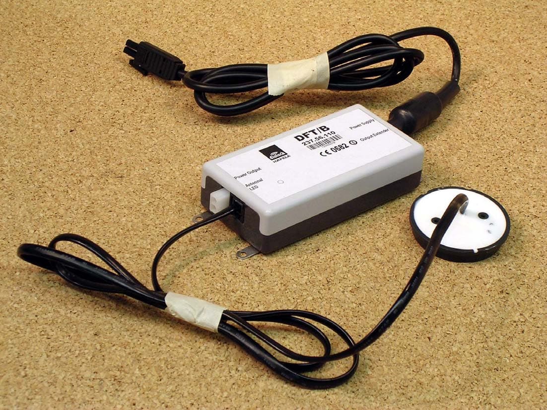
PW3112
Mar 02, 2004Electronic Locking System
Equipment Class
DCD - Part 15 Low Power Transmitter Below 1705 kHz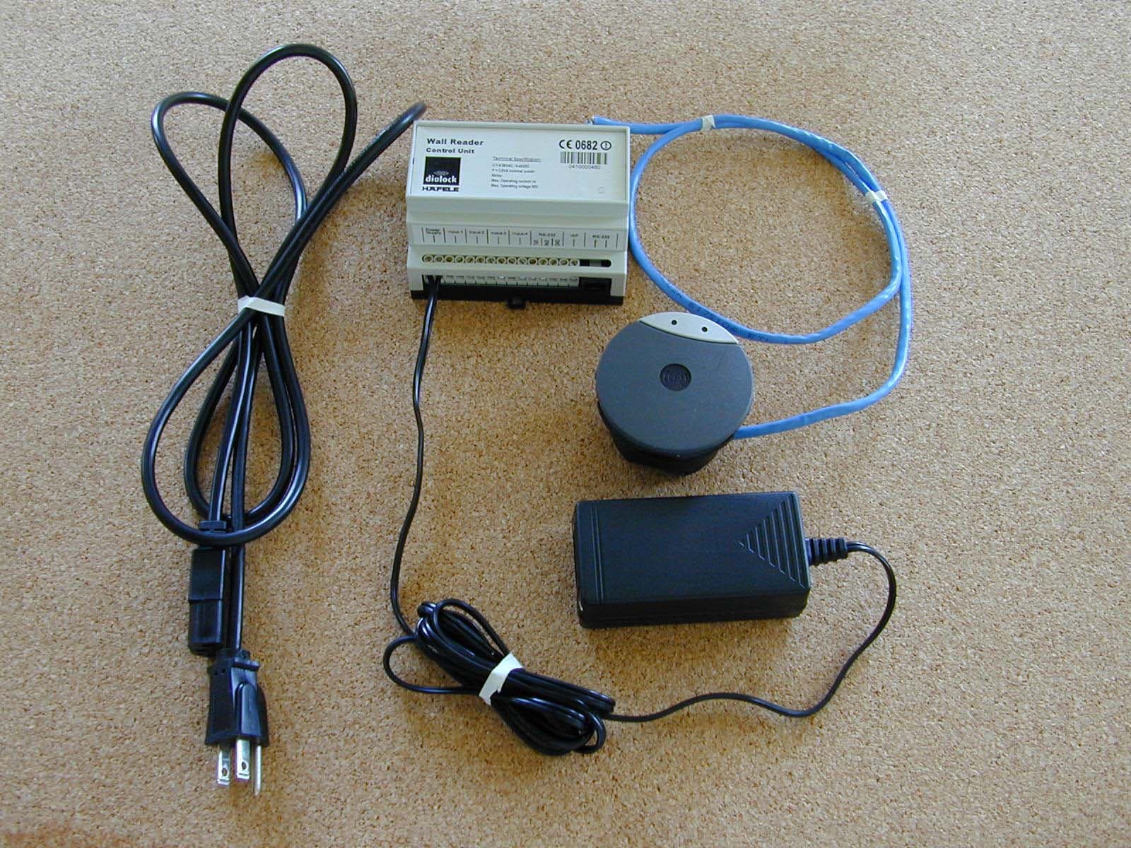
PW3110
Jun 11, 2003RFID System
Equipment Class
DCD - Part 15 Low Power Transmitter Below 1705 kHz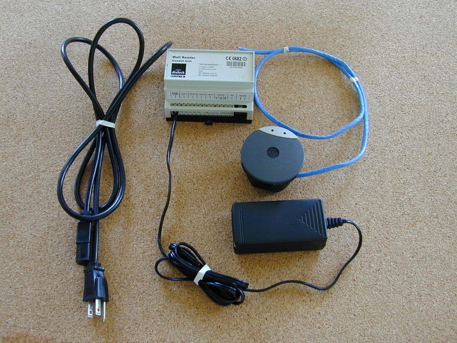
PW3111
Jun 10, 2003RFID System
Equipment Class
DXX - Part 15 Low Power Communication Device Transmitter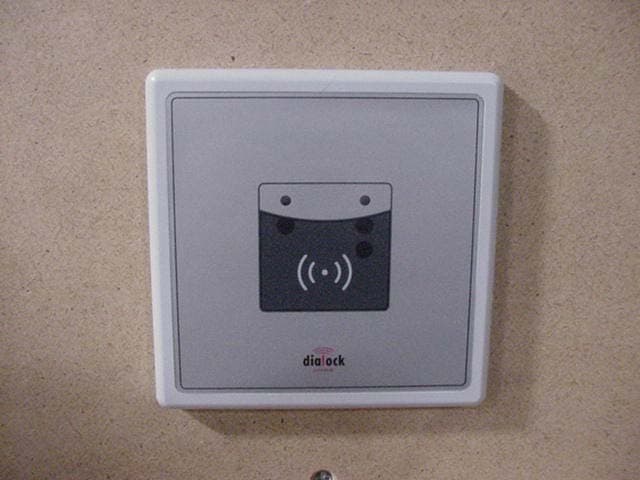
PW3104
Nov 26, 2002Wall-mounted door and lock control
Equipment Class
DCD - Part 15 Low Power Transmitter Below 1705 kHz
PW3108
Aug 19, 2002Doorknob Entry System
Equipment Class
DCD - Part 15 Low Power Transmitter Below 1705 kHz