PW3107Furniture Safe
Hafele America Co.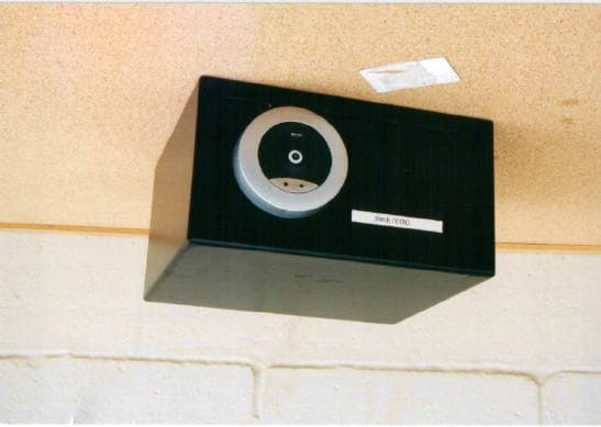
Click to zoom
Application Details
- Equipment Class
- DXX - Part 15 Low Power Communication Device Transmitter
- Date of Grant
- Jun 13, 2002
- Application Purpose
- Original Equipment
- Date of Application
- Jun 13, 2002
- Equipment Note
- Furniture Safe
- Frequency Range
- 13.56000000 - 13.56000000
- Company
- Hafele America Co.
- Country
- United States
Documents & Files
Document Text
Text extracted from the exhibit documents filed with the FCC. Open a document above to read the original.
Users Manual
Re: Certification for Hafele DMT 32 Transmitter Model: DMT 32 FCC ID: PW3107 USER'S MANUAL INFORMATION (PRELIMINARY) The User's Manual is in preparation. The following material will be contained in the manual: FCC ID: PW3107 CANADA: to be provided by IC This device complies with Part 15 of the FCC Rules and with RSS-210 of Industry Canada. Operation is subject to the following two conditions: (1) This device may not cause harmful interference, and (2) This device must accept any interference received, including interference that may cause undesired operation. WARNING: Changes or modifications not expressively approved by the party responsible for compliance could void the user's authority to operate the equipment. Note: This equipment has been tested and found to comply with the limits for a Class B digital device, pursuant to part 15 of the FCC Rules. These limits are designed to provide reasonable protection against harmful interference in a residential installation. This equipment generates, uses, and can radiate radio frequency energy and, if not installed and used in accordance with the instructions, may cause harmful interference to radio communications. However, there is no guarantee that interference will not occur in a particular installation. If this equipment does cause harmful interference to radio or television reception, which can be determined by turning the equipment off and on, the user is encouraged to try to correct the interference by one or more of the following measures: • Reorient or relocate the receiving antenna. • Increase the separation between the equipment and receiver. • Connect the equipment into an outlet on a circuit different from that to which the receiver is connected. • Consult the dealer or an experienced radio/TV technician for help. Mounting instructions engl.9 Technical information All safes are supplied in the basic method of operation. In this method of operation, locking authorisations can be allocated to personnel keys directly at the safe with a special programming key stick (green). The locking authorisations are withdrawn again directly at the safe with a clearing key stick (red). Guest keys are authorised via the software Hotel. The configuration takes place when the system is initiated. Technical data: weight TM3 TM4 thickness of steel material thickness of front plate and door safety level number of locking bolts 13 kg 19 kg, with removable shelf (sheet steel) 2 mm, single walled 6 mm A according to VDMA, norm 24992 2 Mounting instructions 10engl. Supply schedule lsafe lsafe TM4: removable shelf (sheet steel) lfour Mignon-1,5-V-batteries (already inserted) lbattery holder TRE emergency power supply Installation The safe is designed for installation into furniture. 1 2 3 ca. 1,2 m 1end plate (19 mm thick) 2safe 3base plate (35 to 40 mm thick) Mounting instructions engl.11 280 29 318 173 128 248 Built-in dimensions of safe TM3 300 29 398 278 170 295 Built-in dimensions of safe TM4 1. Glue and screw fix the base plate to the side panels of the cabinet at approx. 1.2 m above the cabinet base. 2. Glue and screw fix the end plate to the side panels of the cabinet above the base plate. 3. Insert the safe. Screw fix the safe in the cabinet 1. For screw fixing to the rear panel of the cabinet: from the inside of the safe, push two screws through the 10 mm drillings in the back panel of the safe and screw fix the safe to the cabinet. 2. For screw fixing to the base plate: from the inside of the safe, push four screws through the 8 mm drillings in the base of the safe and screw fix the safe to the base plate. Mounting instructions 12engl. Initiation Allocation of programming and clearing key stick In the basic method of operation, the programming and clearing key sticks must be allocated during the first initiation. Avoid misuse of the electronic keys by unauthorised persons: keep the programming and clearing key sticks in a safe place, as these will allow allocation of locking authorisations to an electronic key. 1. Have the green programming key stick and the red clearing key stick ready. 2. Push the white button on the display of the safe. the green indicator (LED) flashes for a few seconds. 3. Hold the green programming key stick in front of the display, whilst the green LED flashes. The red indicator (LED) is illuminated once as confirmation of the allocation process, afterwards it flashes. 4. Hold the red clearing key stick in front of the display, whilst the red LED flashes. The green indicator (LED) flashes for a few seconds. The safe switches off automatically. If errors occurred during the allocation: ’switch the safe back on. ’re-allocate the programming and clearing key stick. If errors re-occur: ’contact your Dialock sales office. Mounting instructions engl.13 Brief operating instructions for the basic method of operation Allocation of locking authorisations to a personnel key 1. Push the white button on the display. The red indicator (LED) is illuminated. 2. Hold the green programming key stick in front of the display. The green indicator (LED) flashes. 3. Hold the personnel key to be allocated in front of the display within 5 seconds. The green indicator (LED) is illuminated briefly. The access authorisation for the personnel key to be allocated has been given. 4. Remove the allocated personnel key. The safe switches off automatically. If the red indicator (LED) is illuminated, the attempt was unsuccessful: ’repeat the allocation of locking authorisations. 5. Hold the next personnel key to be allocated in front of the display in intervals of 5 seconds. Withdrawal of locking authorisations from the personnel key 1. Push the white button on the display. The red indicator (LED) is illuminated. 2. Hold the red clearing key stick in front of the display. The red indicator (LED) flashes. 3. Hold the personnel key to be deleted in front of the display. The red indicator (LED) is illuminated briefly. The locking authorisation is withdrawn. T…
Text truncated - open the document above for the full version.
Block Diagram
BLOCK DIAGRAM SAFE Legic Microcontroller Program-Memory RTC EEPROM CPU Supervisor Tiris ™ Encoder / Decoder Modulator / Demodulator Full Bridge Driver Antenna Infrared - Interface 1 Mhz 9,6 kBaud 1 Mhz >DC 1 MhzUnknown 12,56 Mhz 12,56 Mhz Motordriver Motor STS20 SCS30 Flatcable
Cover Letter(s)
Re: Certification for Hafele DMT 32 Transmitter Model: DMT 32 FCC ID: PW3107 POWER OF ATTORNEY A letter granting Valdis V. Liepa the Power of Attorney is on file and can be provided when so requested. Re: Certification for Hafele DMT 32 Transmitter Model: DMT 32 FCC ID: PW3107 REQUEST FOR CONFIDENTIALITY Pursuant to 47 CRF 0.459, Hafele America Co. requests that a part of the subject application be held confidential. This comprises Exhibits (5) Schematics (10) Parts List (Part of Exhibit only) Hafele America Co. has spent substantial effort in developing this product and it is one of the first of its kind in industry. Having the subject information easily available to "competition" would negate the advantage they have achieved by developing this product. Not protecting the details of the design will result in financial hardship. If there are any questions regarding this request, please contact me at the above address or call 734-483-4211, fax 734-647-2106 or e-mail [email protected]. Sincerely, Valdis V. Liepa Research Scientist University of Michigan June 2, 2002 Re: Certification for Hafele DMT 32 Transmitter Model: DMT 32 FCC ID: PW3107 STATEMENT OF MODIFICATIONS There were no modifications made to the DUT by this test laboratory. (Also see Section 3.1 of the attached Test Report). _____________________ Valdis V. Liepa Research Scientist Re: Certification for Hafele DMT 32 Transmitter Model: DMT 32 FCC ID: PW3107 GENERAL PRODUCT INFORMATION The device, for which certification is pursued, has been designed by: Hafele America Co. 3901 Cheyenne Dr., PO Box. 4000 Archdale, NC 27263-4000 Mr. John O’Meara Tel: 914-669-5927 Fax: 914-646-8715 It will be manufactured by: Hafele America Co 3901 Cheyenne Dr., PO Box. 4000 Archdale, NC 27263-4000 Mr. John O’Meara Tel: 914-669-5927 Fax: 914-646-8715 It will be marketed and serviced by:
Cover Letter(s)
ATTN: Tim Johnson AmericanTCB The following is our response to your request for further information regarding the Hafele Legic Safe, FCC ID: PW3107. 1) The block diagram shows a frequency to the antenna of 12.56 which does not match the 731, etc. Please comment. There was a type-o on the block diagram. A revised Block Diagram has been submitted, with the frequency corrected to 13.56 MHz. 2) Please provide a photograph of the PCB Front with the coil removed. A photograph has been uploaded. 3) The operational description states that the RF energy charges a capacitor which is used by the transponder to communicate back to the EUT. What is the response frequency of the transponder? The transponder responds at 13.56 Mhz. 4) The test report states that the loop was positioned "in the plane of the loop perpendicular and parallel to the direction of propagation. The loop antenna must also be rotated about horizontal and vertical axis in an attempt to maximize the emission. Was this performed? The emissions were maximized during measurement. All orientations were tested. 5) The Users Manual is missing the statements specified by 15.21 and 15.105. Please provide a corrected users manual. A updated User’s Manual has been submitted and includes both the 15.21 and 15.105 statements. 6) Please explain if this device is being certified under 15.225 or 15.209 (Note the limits appear to be adjusted to 15.209). We are applying to have the device certified under 15.209. Sincerely, Valdis V. Liepa Research Scientist University of Michigan RADLAB
Cover Letter(s)
American Telecommunications Certification Body Inc. 6731 Whittier Ave, McLean, VA 22101 June 7, 2002 RE: Hafele American Co. FCC ID: PW3107 After a review of the submitted information, I have a few comments on the above referenced Application. 1) The block diagram shows a frequency to the antenna of 12.56 which does not match the 731, etc. Please comment. 2) Please provide a photograph of the PCB Front with the coil removed. 3) The operational description states that the RF energy charges a capacitor which is used by the transponder to communicate back to the EUT. What is the response frequency of the transponder? 4) The test report states that the loop was positioned "in the plane of the loop perpendicular and parallel to the direction of propagation. The loop antenna must also be rotated about horizontal and vertical axis in an attempt to maximize the emission. Was this performed? 5) The Users Manual is missing the statements specified by 15.21 and 15.105. Please provide a corrected users manual. 6) Please explain if this device is being certified under 15.225 or 15.209 (Note the limits appear to be adjusted to 15.209). If 15.225 applies then: 7) Please provide frequency stability information for -20 degrees to + 50 degrees C as specified by 15.225(c). ANSI C63.4 (as referenced by 15.31) specifies frequency stability to be performed in 10 degree increments after a sufficient stabilization time period. Please provide the missing test data. 8) The test report states that the Limit has been increased by the dB values given in Section 6.6. The limits do not match 15.225. 9) Further information regarding bandedge compliance would be necessary. Timothy R. Johnson Examining Engineer mailto: [email protected] The items indicated above must be submitted before processing can continue on the above referenced application. Failure to provide the requested information may result in application termination. Correspondence should be considered part of the permanent submission and may be viewed from the Internet after a Grant of Equipment Authorization is issued. Please do not respond to this correspondence using the email reply button. In order for your response to be processed expeditiously, you must submit your documents through the AmericanTCB.com website. Also, please note that partial responses increase processing time and should not be submitted. Any questions about the content of this correspondence should be directed to the sender.
External Photos
DMT 32 (LEGIC) – Front DMT 32 (LEGIC) – Back DMT 32 (LEGIC) – Door Open
Internal Photos
DMT 32 (LEGIC) – Interior Open DMT 32 (LEGIC) – Front Open DMT 32 (LEGIC) – Internal PCB & Lock Mechanism DMT 32 (LEGIC) – Internal PCB Front DMT 32 (LEGIC) – Internal PCB Back DMT 32 (LEGIC) – Face & PCB Front DMT 32 (LEGIC) – Face & PCB Back DMT 32 (LEGIC) – PCB Back DMT 32 (LEGIC) PCB Front with Coil DMT 32 (LEGIC) – PCB Front with Coil
Operational Description
Description of Operation Upon pressing the activation button on the front of the DUT, the DUT interrogates the transponder by initiating a charge phase. This generates an electromagnetic filed around the antenna coil from which the transponder accumulates and stores energy on its internal charge capacitor. This energy is used to power the transponder in the read phase, where it sends back an id/control code after each charging pulse. The code is then validated against a known value and depending on match, the lock is state is changed. The circuit then activates a motor drive which moves the locking mechanism from locked to unlocked, or from unlocked to locked.
Test Report
DMT 32 (TIRIS) – DUT on OATS DMT 32 (TIRIS) – DUT up close
Contact Information
Applicant
Jeff Ratkus(Lighting Product Manager)
Technical Contact
University of Michigan/EECSValdis V Liepa
[email protected]734-483-4211
1301 Beal Ave. · Ann Arbor, Michigan · United States
Non-Technical Contact
University of Michigan/EECSValdis V Liepa
[email protected]734-483-4211
Test Firm
University of MichiganValdis Liepa
Technical Specifications
| # | Rule Parts | Frequency Range | Power Output |
|---|---|---|---|
| 1 | 15C | 13.56 MHz - 13.56 MHz | - |
Other Applications from Hafele America Co.
PW3201
May 13, 2004RFID System
Equipment Class
DXX - Part 15 Low Power Communication Device Transmitter
PW3112
Mar 02, 2004Electronic Locking System
Equipment Class
DCD - Part 15 Low Power Transmitter Below 1705 kHz
PW3110
Jun 11, 2003RFID System
Equipment Class
DCD - Part 15 Low Power Transmitter Below 1705 kHz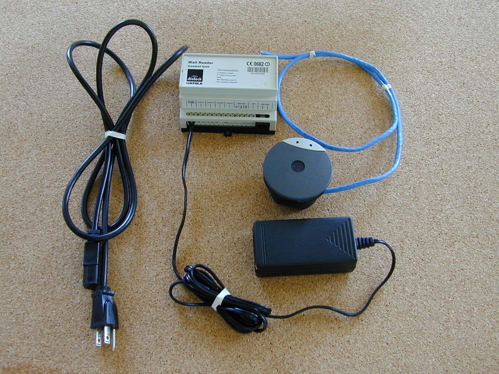
PW3111
Jun 10, 2003RFID System
Equipment Class
DXX - Part 15 Low Power Communication Device Transmitter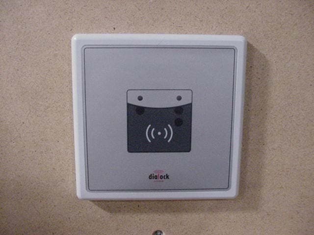
PW3104
Nov 26, 2002Wall-mounted door and lock control
Equipment Class
DCD - Part 15 Low Power Transmitter Below 1705 kHz