PWO075Quint Band Signal Booster
Wilson Electronics, LLC
Click to zoom
Application Details
- Equipment Class
- B2W - Part 20 Wideband Consumer Booster (CMRS)
- Date of Grant
- Jan 10, 2024
- Application Purpose
- Original Equipment
- Date of Application
- Jan 09, 2024
- Equipment Note
- Quint Band Signal Booster
- Frequency Range
- 1930.00000000 - 1995.00000000
- Company
- Wilson Electronics, LLC
- Country
- United States
Documents & Files
Document Text
Text extracted from the exhibit documents filed with the FCC. Open a document above to read the original.
Users Manual
ENTERPRISE 4330 A Wilson Electronics Brand wilsonpro.com866.294.1660 Installation Guide In-Building Cell Signal Amplifier with Multi-Tower Targeting (MTT) Technology ENGLISH Package Contents 1 About The Enterprise 4330 2 Additional Features 4 Installation Diagram 5 Menu System 10 Safety Guidelines 44 Specifications 46 Warranty 47 Index ENTERPRISE 4330 IN-BUILDING CELL SIGNAL AMPLIFIER 1EN Enterprise 4330 Amplifier Enterprise 4330 Amplifier Wide Band Directional Antenna (314411) Wide Band Directional Antenna (314411) Dome Antennas (qty. 4) (304412) Dome Antennas (qty. 4) (304412) 30 m. (100 ft.) Wilson400 Cable (qty. 5) (952300) 30 m. (100 ft.) Wilson400 Cable (qty. 5) (952300) 60 cm. (2 ft.) Wilson400 Cable (952302) 60 cm. (2 ft.) Wilson400 Cable (952302) 50 Ohm Lightning Surge Protector (859902) 50 Ohm Lightning Surge Protector (859902) Enterprise 4330 SKU 460075 Enterprise 4330 SKU 461075 Package Contents IN-BUILDING CELL SIGNAL AMPLIFIER ENTERPRISE 4330 2EN Frequency-specific “split mode” option, facilitating separate outdoor antennas for different bands, resulting in improved indoor coverage. Remote system monitoring. Connects to WilsonPro Cloud service via internal, pre-activated LTE modem or Ethernet. High max downlink power (+17 dBm per port) for up to 100,000 sq ft coverage with a strong “5 bar” outside signal. High max uplink power (up to +26 dBm): will reach distant cell towers. In-Building Cell Signal Amplifier Systems Enterprise 4330 ENTERPRISE 4330 IN-BUILDING CELL SIGNAL AMPLIFIER 3EN The Enterprise 4330 cell signal amplifier systems provides significantly enhanced 4G LTE and 5G coverage inside buildings where cell signals may not otherwise penetrate. Installation of an Enterprise 4330 cell signal amplifier system results in fewer dropped calls, improved voice quality, uninterrupted texts, and faster data speeds—along with better audio and video streaming. For installers and integrators, subscribing to the WilsonPro Cloud means you can sell your clients extended service plans, generating recurring revenue streams for your business. And for your clients, the WilsonPro Cloud provides ultra-high system reliability and guaranteed uptime. The Enterprise 4330 amplifiers connect to the WilsonPro Cloud right out of the box via an LTE connection through the outside antenna, or through a standard hardwired Ethernet port. The wireless LTE connection is included in the annual WilsonPro Cloud subscription, so no additional Internet connection is required. The Enterprise 4330 cell signal amplifier systems also incorporate Wilson Electronics’ state-of-the-art XDR (eXtended Dynamic Range) technology that prevents signal overload conditions which can, in accordance with regulations, force the amplifier to shut down. When the Enterprise 4330 cell signal amplifier systems sense that any incoming cell signal is too strong and threatens to overload the system, XDR automatically reduces amplifier gain to compensate while maintaining signal coverage throughout the building. The Enterprise 4330 cell signal amplifier systems incorporate an easy-to-use color LCD touch screen, and all antenna ports are located on the same side of the unit for simple installation. Like all WilsonPro cell signal amplifiers, the Enterprise 4330 cell signal amplifier systems are universal: they work for all cellular devices, all services and all U.S. and Canada cell phone carriers. IN-BUILDING CELL SIGNAL AMPLIFIER ENTERPRISE 4330 4EN Cellular Network Scanning: Provides RSRP (Reference Signal Received Power) and RSRQ (Reference Signal Received Quality) for major cellular carriers in the U.S. and Canada, measured at the indoor antenna ports. Extended Dynamic Range (XDR) for continuous connectivity: XDR lets the Enterprise 4330 system work with an incoming signal and never shut down due to a strong outside signal. Choice of Wall-Mount or Rack-Mount Installation: All indoor and outdoor port(s) are located on top of the amplifier for easy antenna connections, while an exposed mounting flange on each amplifier provides for simple installation. Onboard Software for Intelligent Control: The amplifier is automatically controlled by onboard software, ensuring connectivity throughout large spaces and multi-story buildings. The amplifier will adjust its gain level up or down as required by the conditions of the immediate signal environment. Color LCD Touch Screen: The Enterprise 4330 system utilize a color LCD touch screen, for assessing amplifier performance and viewing amplifier configuration. Independently Controlled Ports: Four independently controlled indoor antenna ports facilitating up to 100,000 sq. ft. of indoor coverage. 4 Additional Features ENTERPRISE 4330 IN-BUILDING CELL SIGNAL AMPLIFIER 5EN The Enterprise 4330 supports up to four inside antennas and are capable of operating in traditional Common Mode, in which all amplifier cell bands use the same outdoor antenna, or Split Mode, in which cell bands use separate outdoor antennas. Outside Antenna 700-2200 MHz Cell Tower Inside Antenna Amplifier Inside Antenna Inside Antenna Inside Antenna Note: A Wilson Lightning Surge Protector is recommended for all building installations. Make sure the protector is installed outside the building at point of entry connected to a suitable ground and in line between the Outside Antennas and the Signal Amplifier. Common mode can be used for an installation in which cell towers for different bands are located in the same direction. Note: The Enterprise 4330 is configured to common mode by default. Installation Diagram Common Mode IN-BUILDING CELL SIGNAL AMPLIFIER ENTERPRISE 4330 6EN Split mode is advantageous for an installation in which cell towers for different bands are located in different directions. Outdoor directional antennas can be pointed to provide maximum cell coverage for each band. Inside Antenna Outside Antennas 700 MHz Cell Tower 800 MHz Cell Tower 1700-2200 MHz Cell Tower Inside Antenna Amplifier Inside Antenna Inside An…
Text truncated - open the document above for the full version.
Users Manual
IN-BUILDING CELL SIGNAL AMPLIFIER ENTERPRISE 4330 8EN Mount to EIA Standard 19” Server Rack (compliant with EIA-310-D) with 4 standard #10 or #12 cage Screws and Nuts. Please reference the below diagram: WARNING: Proper installation environment to reduce risks related to the environment, the unit must be installed indoors only. It is the consumer’s responsibility to ensure that structural engineering requirements for potential seismic activity are met per your local requirements. This may require wall reinforcement. Do not install near sources of high heat or steam or where condensation is likely to occur, such as near air conditioners. Do not install on a structure that is prone to vibration or movement. The power supply must be plugged into an earthed outlet ONLY. EIA Standard 19” Server Rack Standard #10 or #12 Cage Screws & Nuts MOUNTING SPECIFICATIONS cont.) Rack Mounting Installation ENTERPRISE 4330 IN-BUILDING CELL SIGNAL AMPLIFIER 9EN The Enterprise 4330 systems are designed with advanced internal programming, which allows it to automatically adjust for a variety of conditions, including the added functionality, alerts, and troubleshooting of an enhanced cloud management and monitoring solution. Once the AC power cable and antenna cables are connected, scan the QR code on the Quick Registration Card to add the amplifier to your WilsonPro Cloud account. For detailed instructions see the WilsonPro Cloud section. Post-Install Setup power supply Ethernet & USB location Ethernet & USB location Wall hand tighten ONLY Rack power supply IN-BUILDING CELL SIGNAL AMPLIFIER ENTERPRISE 4330 10EN The Enterprise 4330 takes about 3 minutes to boot up. Once boot up is complete, the home screen will appear, showing the amplification and status of each port and band. Green indicates that a band is operating correctly with maximum allowable gain. Yellow indicates band gain reduction because of an oscillation condition. Reposition antennas (increase separation between indoor and outdoor antennas, and point in opposite directions) and then reboot (turn the unit off & on) the Enterprise 4330 system to reactivate the band and maximize performance. When adequate separation is achieved, the yellow lights will return to green upon reboot. Note: when the light is yellow, the band is operational; however, performance is reduced. Home Screen Start Up Screen Band Menu Color Description Menu System ENTERPRISE 4330 IN-BUILDING CELL SIGNAL AMPLIFIER 11EN Red indicates a band has been shut down because of a severe oscillation condition or repeated oscillation. Reposition antennas (increase separation between indoor and outdoor antennas, and point in opposite directions) and then reboot (turn the unit off & on) the Enterprise 4330 system to reactivate the band and maximize performance. When adequate separation is achieved, the red light(s) will return to green upon reboot. Gray indicates band has been disabled. (MENU SYSTEM cont.) IN-BUILDING CELL SIGNAL AMPLIFIER ENTERPRISE 4330 12EN There are 5 Settings Screens represented by “tabs”. Tap the tab heading to view each Settings Screen. General settings below. Note: Bands and Ports are disabled or enabled from the Cloud or Local Amplifier Configuration Utility only. Tap ‘Settings Icon’ in the lower right corner to view the Settings Screen. Settings Screen ENTERPRISE 4330 IN-BUILDING CELL SIGNAL AMPLIFIER 13EN Ethernet Settings Tab Modem Settings Tab (MENU SYSTEM - SETTINGS SCREEN cont.) IN-BUILDING CELL SIGNAL AMPLIFIER ENTERPRISE 4330 14EN Cloud Communication Settings Tab Antenna Settings Tab Note: The Reset Local Comm button is used in case the user has configured the amplifier such that the Local Amplifier Configuration Utility (LACU) is not accessible, e.g., if the communication preferences are set to “LTE Only” or the LACU password needs to be reset. The “reset” function will renable Ethernet access and also reset the login credentials for LACU to factory defaults. Common Mode is configured from the Local Amplifier Configuration Utility and should be set when using a single Outside Antenna. (MENU SYSTEM - SETTINGS SCREEN cont.) ENTERPRISE 4330 IN-BUILDING CELL SIGNAL AMPLIFIER 15EN Split-Mode Configuration Split Mode is configured from the Local Amplifier Configuration Utility and should be set when using separate Outside Antennas for Band 4/25, Band 5, and Band 12/13. To go back to the Home Screen, tap on the Home Icon (in the lower right corner). (MENU SYSTEM - SETTINGS SCREEN cont.) IN-BUILDING CELL SIGNAL AMPLIFIER ENTERPRISE 4330 16EN To view specific band information (such as the strength of the received uplink & down- link signal, outside signal strength, and amplifier gain status) tap the desired band on the home screen. Oscillation Example Band-Status Screens Note: If the reduced gain due to oscillation is greater than or equal to 60dB, the condition will be displayed as Green and no action is necessary. ENTERPRISE 4330 IN-BUILDING CELL SIGNAL AMPLIFIER 17EN Shutdown Example (MENU SYSTEM - BAND-STATUS SCREENS cont.) IN-BUILDING CELL SIGNAL AMPLIFIER ENTERPRISE 4330 18EN The three icons in the upper right provide status related to the Ethernet connection, Cloud connection, and USB device (if inserted). Ethernet-Status Icon Connectivity Status Screens Cloud-Status Icon ENTERPRISE 4330 IN-BUILDING CELL SIGNAL AMPLIFIER 19EN The Cellular Network Scan screen provides RSRP (Reference Signal Received Power) and RSRQ (Reference Signal Received Quality) for major cellular carriers in U.S. in Canada, measured at the indoor antenna ports (after the signal has been amplified). Band, frequency, bandwidth and cell I.D. are also shown for all cell tower channels found during scanning. Scanning begins as soon as the unit is power on, and is automatic, and continuous. A full scan cycle takes about three minutes to scan all bands and frequencies. Verizon, AT&T, and T-Mobile are reported in the U.S. and Rogers, Telus, Bell, and Freedom are reported in Canada. Cellular Net…
Text truncated - open the document above for the full version.
Attestation Statements
December 12, 2023 Attestation For Wilson Signal Booster: FCC ID PWO075 FEDERAL COMMUNICATIONS COMMISSION Authorization and Evaluation Division 7435 Oakland Mills Road Columbia, MD 21046 RE: Attestation Statements Part 2.911(d)(7) Filing for FCC ID: PWO075 To Whom It May Concern: Ilesh Patel of Wilson Electronics certifies that, as of the date of filing of the application, we designate ourselves as the U.S. agent for service of process. Designated U.S. Agent: Compliance Testing LLC FRN: 0017528332 Name: Wilson Electronics, LLC Address: 3301 E. Deseret Dr., St. George, UT 84790 Contact Person: Ilesh Patel Tel: 469-998-6986 Email: [email protected] Sincerely, Ilesh Patel Senior Engineering Product Manager
Attestation Statements
December 12, 2023 Attestation For Wilson Signal Booster: FCC ID PWO075 FEDERAL COMMUNICATIONS COMMISSION Authorization and Evaluation Division 7435 Oakland Mills Road Columbia, MD 21046 RE: Attestation for FCC ID: PWO075 To Whom It May Concern: Each Signal Booster certificated under FCC ID PWO075 is manufactured and individually tested to ensure FCC compliance: (1) Licensee consent is not required for FCC certification equipment authorization purposes, but licensee consent does remain applicable per 20.21 provisions for both provider specific and wideband boosters. (2) NPS and other compliance/safeguard features have been implemented. (3) NPS and other compliance/safeguard features are defaulted to be “On” (in operation). (4) NPS and other compliance/safeguard features cannot be field reconfigured, disabled, or removed. (5) This consumer booster is not user programmable, does not need fine tuning or adjustment, and does not require professional installation. (6) Future software upgrade will not cause non-compliance. Sincerely, Ilesh Patel Senior Engineering Product Manager
Attestation Statements
Federal Communications Commission Authorization and Evaluation Division 7435 Oakland Mills Road Columbia, MD 21046 USA Date: 01‐10‐2024 Ref: Attestation Statements Part 2.911(d)(5)(i) Filing FCC ID: PWO075 Wilson Electronics LLC (“the applicant”) certifies that the equipment for which authorization is sought is not “covered” equipment prohibited from receiving an equipment authorization pursuant to section 2.903 of the FCC rules. Sincerely, Ilesh Patel Senior Engineering Product Manager Federal Communications Commission Authorization and Evaluation Division 7435 Oakland Mills Road Columbia, MD 21046 USA Date: 05‐09‐2023 Ref: Attestation Statements Part 2.911(d)(5)(ii) Filing FCC ID: PWO074 Wilson Electronics LLC (“the applicant”) certifies that, as of the date of the filing of the application, the applicant is not identified on the Covered List as an entity producing “covered” equipment. Sincerely, Mikel Parry Compliance Manager
Cover Letter(s)
Agent Authorization Letter December 6, 2023 FEDERAL COMMUNICATIONS COMMISSION Authorization and Evaluation Division 7435 Oakland Mills Road Columbia, MD 21046 Subject: Letter of Agent Authorization To Whom It May Concern: Please be advised that we, Wilson Electronics, hereby authorize Compliance Testing LLC to act on our behalf in all matters relating to application for equipment authorization, FCC ID: PWO075, including the signing of all documents relating to these matters. Any and all acts carried out by Wilson Electronics or Compliance Testing LLC in matters pertaining to processes required in the FCC approval shall have the same legal authority as acts and communications by the undersigned. They are authorized to respond to any future issues or FCC requests regarding this project. Please send any query, acknowledgement or response to this letter directly to Wilson Electronics. Sincerely, Ilesh Patel Senior Engineering Product Manager
Cover Letter(s)
December 11, 2023 Federal Communications Commission 7435 Oakland Mills Road Columbia, MD 21046 Subject: Data Confidentiality To Whom It May Concern: Wilson Electronics, Inc. respectfully requests confidentiality of certain documentation provided with the submission of our model 460075 Signal Booster under FCC ID: PWO075 in accordance with sections 0.457 and 0.459 of the Commission’s regulations. We request that the following documents be kept in long-term confidentiality: 1.Schematic Diagram 2.Parts List – Bill of Materials (BOM) 3.Block Diagram 4.Operational Description 5.Internal Photos 1.Due to the fact that there are NO user serviceable parts within the enclosure, there is no reason for internal photos to be publicly accessible. There is also no way for an end user to access the internal components of this unit as it will be installed on a IT rack or on a wall. We request that the following documents be kept in short-term confidentiality until June 30, 2024: 1. Exterior Images 2. Test Setup Photos 3. User Manual The above material is confidential and contains proprietary trade secrets and technical data which must be kept from competitors. Public access to these items could result in duplication of our circuitry and/or techniques thereby reducing our competitive advantage and causing us severe damage. The public disclosure of these materials provides unjustified benefits to its competitors in the market. Sincerely, Ilesh Patel Senior Engineering Product Manager
External Photos
WILSON ELECTRONICS, LLC 3301 E. Deseret Dr, St. George, UT 84790 T.1 800 204 4104 F. 1 435 673 0899 E. info@weboos t.com www.wilsonelectronics.com WILSON ELECTRONICS, LLC 3301 E. Deseret Dr, St. George, UT 84790 T.1 800 204 4104 F. 1 435 673 0899 E. info@weboos t.com www.wilsonelectronics.com WILSON ELECTRONICS, LLC 3301 E. Deseret Dr, St. George, UT 84790 T.1 800 204 4104 F. 1 435 673 0899 E. info@weboos t.com www.wilsonelectronics.com
ID Label/Location Info
WILSON ELECTRONICS, LLC 3301 E. Deseret Dr, St. George, UT 84790 T. 1 800 204 4104 F. 1 435 673 0899 E. [email protected] www.wilsonelectronics.com This Is a CONSUMER ckMce. BEFORE USE, you MUST REGISTER THIS DEVICE with ��'=1:r�=���COO::!�� ��ryou�ust�ll��"'out���.�ou'= operate this ckMce wtth approved anlemas and cables as spedfted by the mamfactur er. Antemas MUST be Installed at least 20 an (8 Indies) from �';_1,,�UST NOT be lnstaled wtu.. 20 an of) any persoo. Yoo MUST cease this ckMce lnmedlatety If reauested by the FCC (or ISED In Canada> or lcensed wireless service ormtder. WARNlf«.. E911 locaUon Information may not be DrOVlded or may be lnacwrate for � served by using this ckMce. This ckMce may be operated ONLY In a fixed lcoatlon 0.e., may operate In a fixed location only) for ln-tuklng use.
Parts List/Tune Up Info
Antenna Kitting Options November 6, 2023 October 27, 2023 Subject: Antenna Kitting Re: FCC ID: PWO075 To Whom It May Concern: The antenna kitting options for models 460075 signal boosters were done for 1 Outside Antenna, and 2 Inside Antenna kit options (qty 4): Fixed Outside Antenna 1. Wide Band Directional With 100' LMR 400 314411-952300 Fixed Indoor Antenna 1. Qty 4 Inside Antenna Kits 304412-952300: Dome w/100' Wilson 400 2. Qty 4 Inside Antenna Kits 311242-952300: Dome w/100' Wilson 400 All equivalent or lesser antennas and cables are suitable for use with 460075 signal boosters. Sincerely, Ilesh Patel Sr. Engineering Product Manager Antenna Kitting Options November 6, 2023 All Outside Antenna Kits with gains less Coax Loss FCC ID: PWO075 Uplink Frequency (MHz) 698-716 777-787 824-849 1710-1755 1850-1915 All Inside Antenna Kits with gains less Coax Loss FCC ID: PWO075 Wide Band Directional Antenna With 100' Wilson 400314411-952300 Antenna Gains (dBi)7.3 7.2 7.8 7.9 9.1 Coax Loss (dB)3.72 3.99 4.79 5.85 7.18 Final Gain less Loss (dB)3.58 3.21 3.01 2.05 1.92 Inside Antenna Kit Dome w/100' Wilson 400 311242-952300 Final Gain less Loss (dB)-2.43 -1.99-2.79 -0.85-1.68 Note: Antenna Gain less Coax Loss as Measured Inside Antenna Kit Dome w/100' Wilson 400 304412-952300 Final Gain less Loss (dB) -2.43 -1.69-3.09 -0.33 -1.29 Note: Antenna Gain less Coax Loss as Measured
RF Exposure Info
December 4, 2023 Subject: RF MPE EXPOSURE Re: FCC ID: PWO075 To Whom It May Concern: The MPE calculations for model 460075 signal booster were done for each frequency band: 700 MHz Band 12, 700 MHz Band 13, 800 MHz Band 5, 1900 MHz Band 25, and 1700/2100 MHz Band 4. For each band, one calculation was done; this included an outside antenna, and an inside antenna that may be connected to this signal booster. The order of the attached calculations is as follows: 700 MHz Band 12: 1. Inside Antenna: 304412‐9523001. Outside Antenna: 314411‐952300 2. Inside Antenna: 311242‐952300 700 MHz Band 13: 1. Inside Antenna: 304412‐952300 2. Inside Antenna: 311242‐952300 800 MHz Band 5: 1. Inside Antenna: 304412‐952300 2. Inside Antenna: 311242‐952300 1900 MHz Band 25: 1. Inside Antenna: 304412‐952300 2. Inside Antenna: 311242‐952300 1700/2100 MHz Band 4: 1. Inside Antenna: 304412‐952300 2. Inside Antenna: 311242‐952300 A booster’s uplink power must not exceed 1 watt equivalent isotropic radiated power (EIRP) for each band of operation. Composite downlink power must not exceed 0.05 watt EIRP for each band of operation (20.21(e)(8)(i)(D)). The following formula was used to calculate the EIRP: EIRP= Power Out (Watts)*Duty Cycle Percent*Antenna Gain (non‐log)*Coax loss (non‐log) The power density (mW/cm 2 ) is calculated using the following formula: Calculated Power Density=1000*EIRP (Watts)/(4*π*(Distance from Antenna (cm)^2)) Sincerely, Ilesh Patel Senior Engineering Product Manager Minimum Safe Distance From Antennas Based upon FCC OET Bulletin 65 and other FCC Sources Band 12 Downlink – 700MHz INPUT DATA Frequency MHz728 Pout Watts0.04898 Duty Cycle Percent100.0% Ant. Gain dBi-2.43 Coax Loss dB0.00 Distance From Antenna In cm20.3 Ant. Gain less Coax Loss dBi-2.43 Distance From Antenna In Inches8.00 EIRP (Watts)0.0280 FCC Power Density Limit (mw/cm 2 )0.49 Calculated Power Density (mw/cm 2 )0.0054 REFERENCE DATA Pout dBm16.90 Antenna Gain (non-log)0.57 Coax loss (non-log)1.00 General FCC Limit (mw/cm 2 )f/1500 RESULTS OF CALCULATIONS Minimum Safe Distance From Antennas Based upon FCC OET Bulletin 65 and other FCC Sources Band 12 Uplink – 700MHz INPUT DATA Frequency MHz698 Pout Watts0.34674 Duty Cycle Percent100.0% Ant. Gain dBi7.30 Coax Loss dB3.72 Distance From Antenna In cm20.3 Ant. Gain less Coax Loss dBi3.58 Distance From Antenna In Inches8.00 EIRP (Watts)0.7907 FCC Power Density Limit (mw/cm 2 )0.47 Calculated Power Density (mw/cm 2 )0.1525 REFERENCE DATA Pout dBm25.40 Antenna Gain (non-log)5.37 Coax loss (non-log)0.42 General FCC Limit (mw/cm 2 )f/1500 RESULTS OF CALCULATIONS Minimum Safe Distance From Antennas Based upon FCC OET Bulletin 65 and other FCC Sources Band 13 Downlink – 700MHz INPUT DATA Frequency MHz746 Pout Watts0.03890 Duty Cycle Percent100.0% Ant. Gain dBi-1.69 Coax Loss dB0.00 Distance From Antenna In cm20.3 Ant. Gain less Coax Loss dBi-1.69 Distance From Antenna In Inches8.00 EIRP (Watts)0.0264 FCC Power Density Limit (mw/cm 2 )0.50 Calculated Power Density (mw/cm 2 )0.0051 REFERENCE DATA Pout dBm15.90 Antenna Gain (non-log)0.68 Coax loss (non-log)1.00 General FCC Limit (mw/cm 2 )f/1500 RESULTS OF CALCULATIONS Minimum Safe Distance From Antennas Based upon FCC OET Bulletin 65 and other FCC Sources Band 13 Uplink – 700MHz INPUT DATA Frequency MHz777 Pout Watts0.34674 Duty Cycle Percent100.0% Ant. Gain dBi7.20 Coax Loss dB3.99 Distance From Antenna In cm20.3 Ant. Gain less Coax Loss dBi3.21 Distance From Antenna In Inches8.00 EIRP (Watts)0.7261 FCC Power Density Limit (mw/cm 2 )0.52 Calculated Power Density (mw/cm 2 )0.1401 REFERENCE DATA Pout dBm25.40 Antenna Gain (non-log)5.25 Coax loss (non-log)0.40 General FCC Limit (mw/cm 2 )f/1500 RESULTS OF CALCULATIONS Minimum Safe Distance From Antennas Based upon FCC OET Bulletin 65 and other FCC Sources Band 5 Downlink – 800MHz INPUT DATA Frequency MHz869 Pout Watts0.04786 Duty Cycle Percent100.0% Ant. Gain dBi-2.79 Coax Loss dB0.00 Distance From Antenna In cm20.3 Ant. Gain less Coax Loss dBi-2.79 Distance From Antenna In Inches8.00 EIRP (Watts)0.0252 FCC Power Density Limit (mw/cm 2 )0.58 Calculated Power Density (mw/cm 2 )0.0049 REFERENCE DATA Pout dBm16.80 Antenna Gain (non-log)0.53 Coax loss (non-log)1.00 General FCC Limit (mw/cm 2 )f/1500 RESULTS OF CALCULATIONS Minimum Safe Distance From Antennas Based upon FCC OET Bulletin 65 and other FCC Sources Band 5 Uplink – 800MHz INPUT DATA Frequency MHz824 Pout Watts0.25704 Duty Cycle Percent100.0% Ant. Gain dBi7.80 Coax Loss dB4.79 Distance From Antenna In cm20.3 Ant. Gain less Coax Loss dBi3.01 Distance From Antenna In Inches8.00 EIRP (Watts)0.5140 FCC Power Density Limit (mw/cm 2 )0.55 Calculated Power Density (mw/cm 2 )0.0992 REFERENCE DATA Pout dBm24.10 Antenna Gain (non-log)6.03 Coax loss (non-log)0.33 General FCC Limit (mw/cm 2 )f/1500 RESULTS OF CALCULATIONS Minimum Safe Distance From Antennas Based upon FCC OET Bulletin 65 and other FCC Sources Band 25 Downlink – 1900MHz INPUT DATA Frequency MHz1930 Pout Watts0.04786 Duty Cycle Percent100.0% Ant. Gain dBi-1.29 Coax Loss dB0.00 Distance From Antenna In cm20.3 Ant. Gain less Coax Loss dBi-1.29 Distance From Antenna In Inches8.00 EIRP (Watts)0.0356 FCC Power Density Limit (mw/cm 2 )1.00 Calculated Power Density (mw/cm 2 )0.0069 REFERENCE DATA Pout dBm16.80 Antenna Gain (non-log)0.74 Coax loss (non-log)1.00 General FCC Limit (mw/cm 2 )1.00 RESULTS OF CALCULATIONS Minimum Safe Distance From Antennas Based upon FCC OET Bulletin 65 and other FCC Sources Band 25 Uplink – 1900MHz INPUT DATA Frequency MHz1850 Pout Watts0.30903 Duty Cycle Percent100.0% Ant. Gain dBi9.10 Coax Loss dB7.18 Distance From Antenna In cm20.3 Ant. Gain less Coax Loss dBi1.92 Distance From Antenna In Inches8.00 EIRP (Watts)0.4808 FCC Power Density Limit (mw/cm 2 )1.00 Calculated Power Density (mw/cm 2 )0.0928 REFERENCE DATA Pout dBm24.90 Antenna Gain (non-log)8.13 Coax loss (non-log)0.19 General FCC Limit (mw/cm 2 )1.00 RESULTS OF CALCULATIONS Minimum Safe Distance Fr…
Text truncated - open the document above for the full version.
Test Report
P2390010_FCC_ Part 20_Rev 1.0 Page 1 of 112 Test Report Prepared for: Wilson Electronics, LLC (weBoost) Model: Enterprise 4330 Series ( 4 inside ports, wall mount and rack mount) Description: Quint Band Signal Booster FCC ID: PWO075 ISED: 4726A-075 To FCC Part 20 ISED RSS-131 (Issue 4) Date of Issue: November 28, 2023 On the behalf of the applicant: Wilson Electronics, LLC (weBoost) 3301 E Deseret Drive St. George, UT 84790 To the attention of: Ilesh Patel, Senior Engineering Product Manager Ph: (435)673-5021 Email: [email protected] Prepared By Compliance Testing, LLC 1724 S. Nevada Way Mesa, AZ 85204 (480) 926-3100 phone / (480) 926-3598 fax www.compliancetesting.com Project No: p2390010 Greg Corbin Project Test Engineer This report may not be reproduced, except in full, without written permission from Compliance Testing. All results contained herein relate only to the sample tested. P2390010_FCC_ Part 20_Rev 1.0 Page 2 of 112 Test Report Revision History Revision Date Revised By Reason for Revision 1.0 11/28/2023 Greg Corbin Original Document P2390010_FCC_ Part 20_Rev 1.0 Page 3 of 112 Table of Contents Description Page Table of Annexes 4 Test Result Summary 5 Standard Test Conditions and Engineering Practices 7 Authorized Frequency Band 11 Spectrum Block Filtering 12 Maximum Power and Gain 16 Intermodulation 34 Out-of-Band Emissions 40 Conducted Spurious Emissions 46 Noise Limits 55 Uplink Inactivity 62 Variable Gain 63 Occupied Bandwidth 67 Anti-Oscillation 68 Oscillation Mitigation 74 Radiated Spurious (with modem TX on) 101 Conducted Spurious Emissions with Modem Transmitting 103 Intermodulation with Modem Transmitting 105 Isolation 108 Measurement Uncertainty 111 Test Equipment Utilized 112 P2390010_FCC_ Part 20_Rev 1.0 Page 4 of 112 Table of Annexes Description Page Annex A Authorized Frequency Band 11 Annex B Spectrum Block Filter 15 Annex C Intermodulation 39 Annex D Out of Band Emission 45 Annex E Conducted Spurious Emission 54 Annex F Noise Power and Uplink Noise Timing 58 Annex G Uplink Inactivity 62 Annex H Uplink Gain Timing 66 Annex I Occupied Bandwidth 67 Annex J Anti-Oscillation 73 Annex K Radiated Spurious Emission (wall mount) 102 Annex L Radiated Spurious Emission (rack mount) 102 Annex M Conducted Spurious Emission with cellular modem on 104 Annex N 3 Tone Intermodulation 107 Annex O Isolation 110 P2390010_FCC_ Part 20_Rev 1.0 Page 5 of 112 Test Result Summary Specification Test Name Pass, Fail, N/A Comments FCC ISED 20.21(e)(3) RSS-131_7.5 Authorized Frequency Band Pass 20.21(e)(3)(i)(B) RSS-131_6.2 Spectrum Block Filter Pass 20.21(e)(8)(i)(B) 20.21(e)(8)(i)(C) 20.21(e)(8)(i)(D) RSS-131_6.1.2 RSS-131_6.2 RSS-131_7.4 Maximum Power and Gain Pass 20.21(e)(8)(i)(F) RSS-131_7.6 Intermodulation Pass 20.21(e)(8)(i)(E) RSS-131_7.5 Out-of-Band Emissions Pass 2.1051 22.917(a) 24.238((a) 27.53(c) 27.53(f) 27.53(g) 27.53(h) RSS-130_4.7.1 RSS-130_4.7.2 RSS-132_5.5 RSS-133_6.5.1 RSS-139_5.6 Conducted Spurious Emissions Pass 20.21(e)(8)(i)(A) RSS-131_7.1 Noise Limits Pass 20.21(e)(8)(i)(I) RSS-131_7.7 Uplink Inactivity Pass 20.21(e)(8)(i)(C)(1) 20.21(e)(8)(i)(H) 20.21(e)(8)(i)(C)(2)(i) (Fixed) RSS-131_7.2 Variable Gain Pass 2.1049 RSS-GEN_6.7 Occupied Bandwidth Pass 20.21(e)(8)(ii)(A) RSS-131_6.1.1 Anti - Oscillation Pass 2.1053 RSS-GEN_6.13 Radiated Spurious Pass KDB Inquiry:883937 N/A Conducted Spurious w/ modem transmitting Pass Additional test required for internal cellular modem KDB Inquiry:883937 N/A 3 tone Intermodulation test w/ modem transmitting Pass Additional test required for internal cellular modem KDB Inquiry:883937 N/A Radiated Spurious w/ modem transmitting Pass Additional test required for internal cellular modem KDB Inquiry:782203 N/A Isolation Pass Additional test required multiple donor ports Statements of conformity are reported as: Pass - the measured value is below the acceptance limit, acceptance limit = test limit. Fail - the measured value is above the acceptance limit, acceptance limit = test limit. P2390010_FCC_ Part 20_Rev 1.0 Page 6 of 112 ANAB Compliance Testing, LLC, has been accredited in accordance with the recognized International…
Text truncated - open the document above for the full version.
Contact Information
Applicant
Ilesh Patel(Senior RF Design Engineer)
Technical Contact
Wilson Electronics, LLCIlesh Patel
[email protected]4699986986
3301 E. Deseret Dr. · St George, Utah · United States
Non-Technical Contact
Wilson Electronics, LLCIlesh Patel
[email protected]4699986986
Test Firm
Compliance Testing, LLCMichael Schafer
[email protected]480-926-3100
Technical Specifications
| # | Rule Parts | Frequency Range | Power Output | Emission | Tolerance |
|---|---|---|---|---|---|
| 32 | 24E | 1.93 GHz - 2.00 GHz | 40.70 mW | G7W | Amp |
Other Applications from Wilson Electronics, LLC
PWO086
Mar 09, 2026Single Band Bi-Directional Amplifier
Equipment Class
B2W - Part 20 Wideband Consumer Booster (CMRS)PWO072
Aug 26, 20245G NR Industrial Signal Booster
Equipment Class
B2I - Part 20 Industrial Booster (CMRS)
PWO460065
Nov 04, 2020Dual Band Signal Booster
Equipment Class
B2W - Part 20 Wideband Consumer Booster (CMRS)
PWO460061
Sep 22, 2020Quint Band Signal Booster
Equipment Class
B2W - Part 20 Wideband Consumer Booster (CMRS)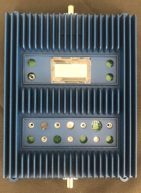
PWO460062
Aug 13, 2020Quint Band Signal Booster
Equipment Class
B2W - Part 20 Wideband Consumer Booster (CMRS)