PWO460062Quint Band Signal Booster
Wilson Electronics, LLC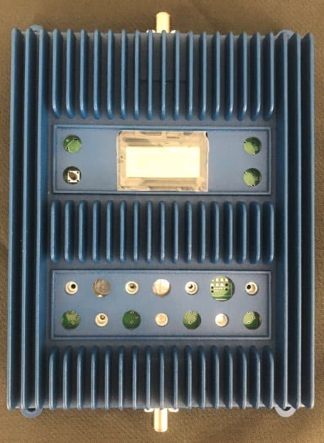
Click to zoom
Application Details
- Equipment Class
- B2W - Part 20 Wideband Consumer Booster (CMRS)
- Date of Grant
- Aug 13, 2020
- Application Purpose
- Original Equipment
- Date of Application
- Aug 11, 2020
- Equipment Note
- Quint Band Signal Booster
- Frequency Range
- 2110.00000000 - 2155.00000000
- Company
- Wilson Electronics, LLC
- Country
- United States
Documents & Files
Document Text
Text extracted from the exhibit documents filed with the FCC. Open a document above to read the original.
Users Manual
ENGLISH Contents: How Cellular Boosters Work . . . . . . . . . . . . . . . . . . . . . . . . . . . . . . . . . . . . . . . . .1 Install Overview . . . . . . . . . . . . . . . . . . . . . . . . . . . . . . . . . . . . . . . . . . . . . . . . . . .1 Kit Options . . . . . . . . . . . . . . . . . . . . . . . . . . . . . . . . . . . . . . . . . . . . . . . . . . . . . . .2 Installation Diagram . . . . . . . . . . . . . . . . . . . . . . . . . . . . . . . . . . . . . . . . . . . . .3 & 4 Outside Antenna Installation . . . . . . . . . . . . . . . . . . . . . . . . . . . . . . . . . . . . . . . . .5 Installing the Inside Antenna(s) . . . . . . . . . . . . . . . . . . . . . . . . . . . . . . . . . . . . . . .7 Installing The Signal Booster . . . . . . . . . . . . . . . . . . . . . . . . . . . . . . . . . . . . . . . . .7 Finding The Strongest Signal . . . . . . . . . . . . . . . . . . . . . . . . . . . . . . . . . . . . . . . .8 Post Install Setup / LCD Screen . . . . . . . . . . . . . . . . . . . . . . . . . . . . . . . . . . . . . .9 Warnings and Recommendations . . . . . . . . . . . . . . . . . . . . . . . . . . . . . . . . . . . .12 Warranty . . . . . . . . . . . . . . . . . . . . . . . . . . . . . . . . . . . . . . . . . . . . . . . . . . . . . . .14 Specifications . . . . . . . . . . . . . . . . . . . . . . . . . . . . . . . . . . . . . . . . . . . .Back Cover Note: This manual contains important safety and operating information . Please read and follow the instructions in this manual . Failure to do so could result in damage to your Signal Booster . Appearance of device and accessories may vary . INSTALLATION GUIDE In-Building SmarTech ® Cellular Signal Boosters PRO 7070 PLUS ™ PRO SERIESSERIES BU-GDE000096-003_050620.indd 1BU-GDE000096-003_050620.indd 15/6/2020 3:05:42 PM5/6/2020 3:05:42 PM 1 2 Contact Wilson Electronics Customer Support Team with any questions at 866-294-1660 or email: [email protected] ENGLISH 1 . Select a location on the roof or outside of the building to install the outside antenna . Refer to pages 3 & 5 . 2 . Select a location to install the Signal Booster that is away from excessive heat, direct sunlight or moisture, and has adequate ventilation . Airtight enclosures are not recommended . Booster should be as close to the outside antenna as possible in order to minimize losses from cable length to outside antenna . Install Overview Refer to Installation Diagram on page 3 & 4 . Contact Wilson Electronics Technical Support Team with any questions at 866-839-9361 . How a Cellular Booster Improves Indoor Signals Wilson cellular signal booster systems work as follows: an outdoor antenna placed on a building where some cell signal is present, (ideally on a roof or pole), receives and sends that weak signal via coax cable (like used in satellite TV installs) to a signal booster located indoors . That weak signal is amplified by the booster and delivered via coax cable to an inside antenna(s) which rebroadcasts the amplified signal within one or several areas where improved signal is required . Signals from indoor cell device(s) are likewise picked up by the inside antenna(s), amplified by the signal booster and transmitted back to the cell tower via the outside antenna . The improved signals result in reliable cellular connections for indoor users . About Gain and Improved Signal Area The less signal strength at the outside antenna’s location and/or the greater the coverage need, the more gain will be required . Conversely, the more signal present outside, the greater the inside coverage area will be . Proper aiming of the outside antenna towards the source of the cell signal is also important . The gains of the outside and inside antenna, though reduced by losses from coax cable lengths, also affect area of improved coverage . Placement of the inside antenna is also a factor as they have directional characteristics . Inside wall materials will also affect indoor coverage area . Another important factor affecting coverage area is inadequate isolation between outside and inside antenna(s) . Wilson boosters are designed to reduce their internal gain in order to prevent any feedback “oscillations” which if unchecked, could affect nearby cell site operation . The LCD status display on the booster is used to determine if a booster is operating at optimal gain for each cellular band . Optimal gain can be achieved by increasing antenna separation, i .e . isolation, until the max gain is indicated . If attainable separation is limited by a building’s layout, gain will suffer . A nearby cell site, even if not providing service to a user, can also cause the booster’s automatic network protection circuitry to reduce gain or even turn off one or more of the booster’s bands so as to prevent signal overload to the nearby site . The display on the booster can also be used to determine if this condition is taking place . Refer to pages 9-11 for explanation of the booster status display . BU-GDE000096-003_050620.indd 1BU-GDE000096-003_050620.indd 15/6/2020 3:05:42 PM5/6/2020 3:05:42 PM 1 2 Contact Wilson Electronics Customer Support Team with any questions at 866-294-1660 or email: [email protected] ENGLISH Pro 70 Plus 2’ RG11Lightning Surge Protector Wide Band Directional Antenna 75’ RG11 Wide Band Panel Antenna 50' RG11 460127 Kit 460227 Kit Pro 70 Plus AC/DC Power Supply 12V/3A AC/DC Power Supply 12V/3A 2’ RG11Lightning Surge Protector Wide Band Directional Antenna 75' RG11 4G Dome Ceiling Antenna 50’ RG11 3 . Connect the cable from the outside antenna to the signal booster’s “outside antenna” connector . Refer to page 6 for more information on running cable . Lightning Surge Protection is recommended for all in-building installations . Refer to pages 3 & 6 . 4 . Select a location for the inside antenna . Try to choose a position in the center of the area needing improved signal . Keep in mind that proper inside antenna to outside antenna isolation is necessary for the…
Text truncated - open the document above for the full version.
Attestation Statements
June 26, 2020 Antenna Kitting Information Model 460062 Signal Booster Accessory Kit Options Component Type Product Number Gain (dBi) / Loss (dB) B12 700 MHz B13 700 MHz B5 800 MHz B4 1700 MHz B2 1900 MHz B4 2200 MHz Outdoor Antenna Directional 314475 7.5 7.5 7.3 8.8 8.8 8.8 314411 7.5 7.5 7.3 8.8 8.8 8.8 Omni 304422 2 2 2 5 5 5 304423 2 2 2 5 5 5 304421 2 2 2 4 4 4 304424 2 2 2 4 4 4 Outdoor Cable Wilson 400 (75 ft) 952375 2.6 2.6 2.8 4.3 4.6 5 RG-11 (75 ft) 951175 3.1 3.1 3.4 5.5 6.0 6.6 Indoor Cable Wilson 400 (60 ft) 952360 2.3 2.3 2.5 3.7 3.9 4.3 RG-11 (50 ft) 951150 2.1 2.1 2.2 3.7 4.0 4.4 Indoor Antenna Dome 304412 2 2 2 4 4 4 304419 2 2 2 4 4 4 Panel 311135 5.2 5.2 4.4 10.1 10.6 8.2 311155 5.2 5.2 4.4 10.1 10.6 8.2 *All equivalent or lesser antennas and cables are suitable for use with 460062 signal boosters Accessory Kit Options Component Type Product Number Gain/Loss B12 700 MHz B13 700 MHz B5 800 MHz B4 1700 MHz B2 1900 MHz B4 2200 MHz Outdoor Antenna Panel 314473 5.2 5.2 4.4 10.1 10.6 8.2 Directional 301111 10 10 10.8 -6.8 -13.8 -13.8 311228 12 12 12 12.9 13.1 11.2 314475 7.5 7.5 7.3 8.8 8.8 8.8 314445 7.2 7.2 6.9 8.9 8.4 9.2 Omni 304423 2 2 2 5 5 5 304421 2 2 2 4 4 4 Outdoor Cable RG-6 (Qty: 2 50ft) 290650 8.5 9 9.3 14.1 14.8 16 Indoor Cable RG-6 (50ft) 290650 4.3 4.5 4.7 7.1 7.4 8 Indoor Antenna Dome 304419 2 2 2 4 4 4 Panel 301211 -0.8 -0.8 1.5 2.4 3.4 1.2 311155 5.2 5.2 4.4 10.1 10.6 8.2 314440 5.75 5.75 6 7.3 7.3 7.6 314444 5.75 5.75 6 7.3 7.3 7.6 *All equivalent or lesser antennas and cables are suitable for use with 460062 signal boosters END OF REPORT
Attestation Statements
July 6, 2020 Attestation For Wilson Signal Booster: FCC ID PWO460062 FEDERAL COMMUNICATIONS COMMISSION Authorization and Evaluation Division 7435 Oakland Mills Road Columbia, MD 21046 RE: Attestation for FCC ID: PWO460062 To Whom It May Concern: Each Signal Booster certificated under FCC ID PWO460062 is manufactured and individually tested to ensure FCC compliance: (1) Licensee consent is not required for FCC certification equipment authorization purposes, but licensee consent does remain applicable per 20.21 provisions for both provider specific and wideband boosters. (2) NPS and other compliance/safeguard features have been implemented. (3) NPS and other compliance/safeguard features are defaulted to be “On” (in operation). (4) NPS and other compliance/safeguard features cannot be field reconfigured, disabled, or removed. (5) This consumer booster is not user programmable, does not need fine tuning or adjustment, and does not require professional installation. (6) Future software upgrade will not cause non-compliance. Sincerely, Mikel Parry Compliance Manager
Attestation Statements
Mobile Station Coupling Losses (MSCL) June 26, 2020 FCCID: PWO460062 The following formulas were used to calculate MSCL with a 2 m path loss and a 45 degree polarity mismatch between the inside antenna and the mobile device for EUT model 460062 signal booster: 푴푴푴푴푴푴푴푴 ( 풅풅풅풅 ) =푷푷푷푷푷푷푷푷 푴푴푳푳푳푳푳푳 ( 풅풅풅풅 ) +푷푷푳푳푷푷푷푷푷푷푷푷푷푷푷푷 푴푴푳푳푳푳푳푳 ( 풅풅풅풅 ) −푮푮 푷푷 −푮푮 푷푷 푃푃푃푃푃푃 ℎ 퐿퐿퐿퐿퐿퐿퐿퐿 ( 푑푑푑푑 ) =20log ( 푑푑 ) +20log ( 푓푓 ) −27.55 푓푓=푓푓푓푓푓푓푓푓푓푓푓푓푓푓푓푓푓푓 푀푀푀푀푀푀 푑푑=퐷퐷퐷퐷 퐿퐿푃푃푃푃푓푓푓푓푓푓 푓푓푓푓 퐿퐿푓푓 푃푃푓푓푃푃푓푓퐿퐿푓푓푓푓푃푃푃푃푓푓푓푓 푃푃퐿퐿 푓푓푓푓푓푓푓푓퐷퐷 푟푟푓푓푓푓 푃푃푓푓푃푃푓푓푓푓푓푓푃푃 (푓푓푓푓푃푃푓푓푓푓퐿퐿) 푃푃퐿퐿푃푃푃푃푓푓퐷퐷 푃푃푓푓 퐿퐿퐿퐿퐿퐿퐿퐿 ( 푑푑푑푑 ) =20log� 퐸퐸 1 퐸퐸 2 � 푃푃퐿퐿푃푃푃푃푓푓퐷퐷 푃푃푓푓 퐿퐿퐿퐿퐿퐿퐿퐿=20log� 퐸퐸 1 퐸퐸 1 sin (휏휏) �, 휏휏=45° 퐸퐸 1 =푀푀푃푃푀푀 퐷퐷푓푓푓푓푓푓 푝푝퐿퐿퐿퐿퐿퐿퐷퐷 푝푝푃푃푓푓 푓푓푃푃푚푚푓푓퐷퐷푃푃푓푓푑푑푓푓 퐿퐿푓푓 푃푃ℎ푓푓 퐸퐸푃푃푓푓푓푓푃푃푓푓퐷퐷푓푓 퐹퐹퐷퐷푓푓푃푃푑푑 푓푓푓푓 퐿퐿푓푓 푀푀퐿퐿푝푝퐷퐷푃푃푓푓 퐷퐷푓푓푟푟 퐷퐷푓푓푓푓 퐸퐸 2 =푀푀푃푃푚푚푓푓퐷퐷푃푃푓푓푑푑푓푓 퐿퐿푓푓 푃푃ℎ푓푓 푓푓푃푃푓푓푓푓푃푃푓푓퐷퐷푓푓 푓푓퐷퐷푓푓 푃푃푑푑 푓푓푓푓 퐿퐿푓푓 푃푃ℎ푓푓 푀푀퐿퐿푝푝퐷퐷푃푃푓푓 퐷퐷푓푓푟푟 퐷퐷푓푓푓푓 푤푤퐷퐷푃푃ℎ 푃푃 45° 푝푝퐿퐿푃푃푃푃푓푓퐷퐷 푃푃푓푓 푓푓퐷퐷퐿퐿푓푓푃푃푃푃푓푓ℎ 퐸퐸 2 =퐸퐸 1 sin ( 휏휏 ) 퐺퐺 푡푡 =푈푈퐸퐸 푇푇푓푓푃푃푓푓퐿퐿푓푓퐷퐷푃푃푃푃푓푓푓푓 퐴퐴푓푓푃푃푓푓푓푓푓푓푃푃 퐺퐺푃푃퐷퐷푓푓 퐺퐺 푟푟 =푆푆퐷퐷푚푚푓푓푃푃푃푃 푑푑퐿퐿퐿퐿퐿퐿푃푃푓푓푓푓 푆푆푓푓푓푓푟푟푓푓푓푓 퐴퐴푓푓푃푃푓푓푓푓푓푓푃푃 퐺퐺푃푃퐷퐷푓푓 Path Loss Evaluation 푃푃푃푃푃푃 ℎ 퐿퐿퐿퐿퐿퐿퐿퐿 ( 푑푑푑푑 ) =20log ( 푑푑 ) +20log ( 푓푓 ) −27.55 푓푓=푓푓푓푓푓푓푓푓푓푓푓푓푓푓푓푓푓푓 퐷퐷푓푓 푀푀푀푀푀푀 푑푑=퐷퐷퐷퐷 퐿퐿푃푃푃푃푓푓푓푓푓푓 푓푓푓푓 퐿퐿푓푓 푃푃푓푓푃푃푓푓퐿퐿푓푓푓푓푃푃푃푃푓푓푓푓 푃푃퐿퐿 푓푓푓푓푓푓푓푓퐷퐷 푟푟푓푓푓푓 푃푃푓푓푃푃푓푓푓푓푓푓푃푃 (푓푓푓푓푃푃푓푓푓푓퐿퐿) Frequency Range (MHz) f (MHz) d (m) Constant (dB) Path Loss (dB) 698-716 707 2 27.55 35.4 776-787 781.5 2 27.55 36.3 824-849 836.5 2 27.55 36.9 1710-1785 1747.5 2 27.55 43.3 1850-1915 1882.5 2 27.55 44.0 Polarity Loss Evaluation 푃푃퐿퐿푃푃푃푃푓푓퐷퐷 푃푃푓푓 퐿퐿퐿퐿퐿퐿퐿퐿 ( 푑푑푑푑 ) =20log� 퐸퐸 1 퐸퐸 2 � 푃푃퐿퐿푃푃푃푃푓푓퐷퐷 푃푃푓푓 퐿퐿퐿퐿퐿퐿퐿퐿 (푑푑푑푑) =20log� 퐸퐸 1 퐸퐸 1 sin (휏휏) �, 휏휏=45° 퐸퐸 1 =푀푀푃푃푀푀 퐷퐷푓푓푓푓푓푓 푝푝퐿퐿퐿퐿퐿퐿퐷퐷 푝푝푃푃푓푓 푓푓푃푃푚푚푓푓퐷퐷푃푃푓푓푑푑푓푓 퐿퐿푓푓 푃푃ℎ푓푓 퐸퐸푃푃푓푓푓푓푃푃푓푓퐷퐷푓푓 퐹퐹퐷퐷푓푓푃푃푑푑 푓푓푓푓 퐿퐿푓푓 푀푀퐿퐿푝푝퐷퐷푃푃푓푓 퐷퐷푓푓푟푟 퐷퐷푓푓푓푓 퐸퐸 2 =푀푀푃푃푚푚푓푓퐷퐷푃푃푓푓푑푑푓푓 퐿퐿푓푓 푃푃ℎ푓푓 푓푓푃푃푓푓푓푓푃푃푓푓퐷퐷푓푓 푓푓퐷퐷푓푓 푃푃푑푑 푓푓푓푓 퐿퐿푓푓 푃푃ℎ푓푓 푀푀퐿퐿푝푝퐷퐷푃푃푓푓 퐷퐷푓푓푟푟 퐷퐷푓푓푓푓 푤푤퐷퐷푃푃ℎ 푃푃 45° 푝푝퐿퐿푃푃푃푃푓푓퐷퐷 푃푃푓푓 푓푓퐷퐷퐿퐿푓푓푃푃푃푃푓푓ℎ 퐸퐸 2 =퐸퐸 1 sin ( 휏휏 ) 푃푃퐿퐿푃푃푃푃푓푓퐷퐷 푃푃푓푓 퐿퐿퐿퐿퐿퐿퐿퐿=20log� 1 퐿퐿퐷퐷푓푓 � 휋휋 180 � �=ퟑퟑ.ퟎퟎퟎퟎ 풅풅풅풅 UE Transmitter Antenna Gain Evaluation 퐺퐺 푡푡 =푈푈퐸퐸 푇푇푓푓푃푃푓푓퐿퐿푓푓퐷퐷푃푃푃푃푓푓푓푓 퐴퐴푓푓푃푃푓푓푓푓푓푓푃푃 퐺퐺푃푃퐷퐷푓푓=ퟎퟎ 풅풅풅풅 푷푷 Signal Booster Server Antenna Gain Evaluation Component Type Product Number Gain (dBi) / Loss (dB) B12 700 MHz B13 700 MHz B5 800 MHz B4 1700 MHz B2 1900 MHz B4 2200 MHz Indoor Cable Wilson 400 (60ft) 952360 2.3 2.3 2.5 3.7 3.9 4.3 RG-11 (50 ft) 951150 2.1 2.1 2.2 3.7 4.0 4.4 Server Antenna Dome 304412, 19 2 2 2 4 4 4 Panel 311135, 55 5.2 5.2 4.4 10.1 10.6 8.2 Minimum MSCL Evaluation Maximum antenna gain and minimum coax loss was selected to calculate “worst case” limit for MSCL B12 700 MHz B13 700 MHz B5 800 MHz B4 1700 MHz B2 1900 MHz Path Loss (dB) 35.4 36.3 36.9 43.3 44.0 Polarity Loss (dB) 3.01 3.01 3.01 3.01 3.01 UE Antenna Gain (dBi) 0 0 0 0 0 Server Antenna Gain (dBi) 5.2 5.2 4.4 10.1 10.6 Server Coax Loss (dB) 2.1 2.1 2.2 3.7 3.9 Minimum MSCL (dB) 35.31 36.21 37.71 39.91 40.31 END OF REPORT
Cover Letter(s)
Agent Authorization Letter July 6, 2020 FEDERAL COMMUNICATIONS COMMISSION Authorization and Evaluation Division 7435 Oakland Mills Road Columbia, MD 21046 Subject: Letter of Agent Authorization To Whom It May Concern: Please be advised that we, Wilson Electronics, hereby authorize H.B. Compliance Solutions to act on our behalf in all matters relating to application for equipment authorization, FCC ID: PWO 460062, including the signing of all documents relating to these matters. Any and all acts carried out by Wilson Electronics or H.B. Compliance Solutions in matters pertaining to processes required in the FCC approval shall have the same legal authority as acts and communications by the undersigned. They are authorized to respond to any future issues or FCC requests regarding this project. Please send any query, acknowledgement or response to this letter directly to Wilson Electronics. Sincerely, Mikel Parry Compliance Manager
Cover Letter(s)
August 10, 2020 Federal Communications Commission 7435 Oakland Mills Road Columbia, MD 21046 Subject: Data Confidentiality To Whom It May Concern: Wilson Electronics, Inc. respectfully requests confidentiality of certain documentation provided with the submission of our model 460062 Signal Booster under FCC ID: PWO460062 in accordance with sections 0.457 and 0.459 of the Commission’s regulations. We request that the following documents be kept in long-term confidentiality: 1. Schematic Diagram 2. Parts List – Bill of Materials (BOM) 3. Block Diagram 4. Operational Description 5. Final Amplification Stage Voltage and Current We request that the following documents be kept in short-term confidentiality until December 31, 2020: 1. Exterior Images 2. Test Setup Photos 3. Internal Photos 4. User Manual The above material is confidential and contains proprietary trade secrets and technical data which must be kept from competitors. Public access to these items could result in duplication of our circuitry and/or techniques thereby reducing our competitive advantage and causing us severe damage. The public disclosure of these materials provides unjustified benefits to its competitors in the market. Sincerely, Mikel Parry Compliance Manager
RF Exposure Info
RF MPE EXPOSURE August 14, 2020 FCC ID: PWO460062 The MPE calculations for EUT model 460062 signal booster were done for frequency bands: • 700 MHz (Band 12) • 700 MHz (Band 13) • 800 MHz (Band 5) • 1900 MHz (Band 2) • 1700/2100 MHz (Band 4) Antennas recommended for the EUT: Port Frequency Range (MHz) Antenna Product Number Coax Product Number Maximum Antenna Gain (dBi) Minimum Coax Loss (dB) Gain - Coax Loss (unitless) Donor 698-716 314475 952375 7.5 2.6 3.1 Donor 777-787 314475 952375 7.5 2.6 3.1 Donor 824-849 314475 952375 7.3 2.8 2.8 Donor 1710-1785 314475 952375 8.8 4.3 2.8 Donor 1850-1915 314475 952375 8.8 4.6 2.6 Server 728-746 311155 951150 5.2 2.1 2.0 Server 746-756 311155 951150 5.2 2.1 2.0 Server 869-894 311155 951150 4.4 2.2 1.7 Server 1930-1995 311155 952360 10.6 3.9 4.7 Server 2110-2155 311155 952360 8.2 4.3 2.5 *Maximum antenna gain and minimum cable losses were selected to compute “worst case” limit and are indicated in the antenna kitting specification for model 460062 EUT Operating Limits Limits for Uncontrolled Exposure 47 CFR 1.1310 Table 1(B) Frequency Range (MHz) Limit (mw/cm^2) 0.3-1.234 100 1.24-30 180/f^2 30-300 0.2 300-1500 f/1500 1500-100,000 1 EUT Operating Limits Evaluation Port Frequency Range (MHz) EUT Maximum Output power dBm (mw) Power density limit (mw/cm^2) Power density evaluation (mw/cm^2) Minimum safe distance (cm) Donor 698-716 23.03 (200.91) 0.47 0.124 20 Donor 777-787 20.5 (112.20) 0.52 0.069 20 Donor 824-849 24.3 (270.40) 0.55 0.152 20 Donor 1710-1785 22.2 (167.11) 1 0.094 20 Donor 1850-1915 24.6 (288.40) 1 0.151 20 Server 728-746 11.7 (14.62) 0.49 0.006 20 Server 746-756 10.6 (11.48) 0.50 0.005 20 Server 869-894 11.5 (14.06) 0.58 0.005 20 Server 1930-1995 9.9 (9.84) 1 0.009 20 Server 2110-2155 11.8 (14.96) 1 0.007 20 *The lowest frequency in each band was used to compute the “worst case” limit. NOTE: Simultaneous transmission does not apply to consumer boosters as the output power is capped at 30 dBm EIRP regardless of how many signals are present. EUT Power Density Evaluation Calculated power density - Uplink: Band 12 (698-716 MHz) Power density is calculated using maximum uplink transmitted power of 200.91 mw and unitless antenna gain less coax loss of 3.1 S = P t G 4πr 2 = (200.91)(3.1) 4휋휋20 2 =0.124 (푚푚푚푚 푐푐푚푚 2 ⁄ ) 푆푆=푃푃푃푃푚푚 푃푃푃푃 퐷퐷푃푃퐷퐷퐷퐷퐷퐷퐷퐷퐷퐷 ( 푚푚푚푚 푐푐푚푚 2 ⁄) 푃푃 푡푡 =푇푇푃푃푇푇퐷퐷퐷퐷푚푚퐷퐷퐷퐷퐷퐷푃푃푃푃 푃푃푃푃푚푚 푃푃푃푃 ( 푚푚푚푚 ) 퐺퐺=퐴퐴퐷퐷퐷퐷푃푃퐷퐷퐷퐷푇푇 퐺퐺푇푇퐷퐷퐷퐷 ( 퐷퐷푃푃퐷퐷푛푛 푃푃푛푛 ) ∗퐶퐶푃푃푇푇퐶퐶 퐿퐿푃푃퐷퐷퐷퐷 ( 퐷퐷푃푃퐷퐷푛푛 푃푃푛푛 ) ∗푑푑푑푑퐷퐷퐷퐷 푐푐퐷퐷푐푐푛푛푃푃 ( % ) 푃푃=퐷퐷퐷퐷퐷퐷퐷퐷 푇푇퐷퐷푐푐푃푃 퐷퐷푃푃 푐푐푃푃퐷퐷퐷퐷푃푃푃푃 푃푃표표 푃푃푇푇푑푑퐷퐷푇푇퐷퐷퐷퐷푃푃퐷퐷 푃푃표표 푇푇퐷퐷퐷퐷푃푃퐷퐷퐷퐷푇푇 (푐푐푚푚) At the minimum safe distance of 20 cm, the power density of the EUT is 0.124 (푚푚푚푚 푐푐푚푚 2 ⁄ ), which is less than the operational limit of 0.47 (푚푚푚푚 푐푐푚푚 2 ⁄ ). Therefore, no minimum safe distance calculation is required. Band 13 (777-787 MHz) Power density is calculated using maximum uplink transmitted power of 112.2 mw and unitless antenna gain less coax loss of 3.1 S = P t G 4πr 2 = (112.2)(3.1) 4휋휋20 2 =0.069 (푚푚푚푚 푐푐푚푚 2 ⁄ ) 푆푆=푃푃푃푃푚푚 푃푃푃푃 퐷퐷푃푃퐷퐷퐷퐷퐷퐷퐷퐷퐷퐷 ( 푚푚푚푚 푐푐푚푚 2 ⁄) 푃푃 푡푡 =푇푇푃푃푇푇퐷퐷퐷퐷푚푚퐷퐷퐷퐷퐷퐷푃푃푃푃 푃푃푃푃푚푚 푃푃푃푃 ( 푚푚푚푚 ) 퐺퐺=퐴퐴퐷퐷퐷퐷푃푃퐷퐷퐷퐷푇푇 퐺퐺푇푇퐷퐷퐷퐷 ( 퐷퐷푃푃퐷퐷푛푛 푃푃푛푛 ) ∗퐶퐶푃푃푇푇퐶퐶 퐿퐿푃푃퐷퐷퐷퐷 ( 퐷퐷푃푃퐷퐷푛푛 푃푃푛푛 ) ∗푑푑푑푑퐷퐷퐷퐷 푐푐퐷퐷푐푐푛푛푃푃 ( % ) 푃푃=퐷퐷퐷퐷퐷퐷퐷퐷 푇푇퐷퐷푐푐푃푃 퐷퐷푃푃 푐푐푃푃퐷퐷퐷퐷푃푃푃푃 푃푃표표 푃푃푇푇푑푑퐷퐷푇푇퐷퐷퐷퐷푃푃퐷퐷 푃푃표표 푇푇퐷퐷퐷퐷푃푃퐷퐷퐷퐷푇푇 (푐푐푚푚) At the minimum safe distance of 20 cm, the power density of the EUT is 0.069 (푚푚푚푚 푐푐푚푚 2 ⁄ ), which is less than the operational limit of 0.52 (푚푚푚푚 푐푐푚푚 2 ⁄ ). Therefore, no minimum safe distance calculation is required. Band 5 (824-849 MHz) Power density is calculated using maximum uplink transmitted power of 270.4 mw and unitless antenna gain less coax loss of 2.8 S = P t G 4πr 2 = (270.4)(2.8) 4휋휋20 2 =0.152 (푚푚푚푚 푐푐푚푚 2 ⁄ ) 푆푆=푃푃푃푃푚푚 푃푃푃푃 퐷퐷푃푃 퐷퐷퐷퐷퐷퐷퐷퐷퐷퐷 ( 푚푚푚푚 푐푐푚푚 2 ⁄) 푃푃 푡푡 =푇푇푃푃푇푇퐷퐷퐷퐷푚푚퐷퐷퐷퐷퐷퐷푃푃푃푃 푃푃푃푃푚푚 푃푃푃푃 ( 푚푚푚푚 ) 퐺퐺=퐴퐴퐷퐷퐷퐷푃푃퐷퐷퐷퐷푇푇 퐺퐺푇푇퐷퐷퐷퐷 ( 퐷퐷푃푃퐷퐷푛푛 푃푃푛푛 ) ∗퐶퐶푃푃푇푇퐶퐶 퐿퐿푃푃퐷퐷퐷퐷 ( 퐷퐷푃푃퐷퐷푛푛 푃푃푛푛 ) ∗푑푑푑푑퐷퐷퐷퐷 푐푐퐷퐷푐푐푛푛푃푃 ( % ) 푃푃=퐷퐷퐷퐷퐷퐷퐷퐷 푇푇퐷퐷푐푐푃푃 퐷퐷푃푃 푐푐푃푃퐷퐷퐷퐷푃푃푃푃 푃푃표표 푃푃푇푇푑푑퐷퐷푇푇퐷퐷퐷퐷푃푃퐷퐷 푃푃표표 푇푇퐷퐷퐷퐷푃푃퐷퐷퐷퐷푇푇 (푐푐푚푚) At the minimum safe distance of 20 cm, the power density of the EUT is 0.152 (푚푚푚푚 푐푐푚푚 2 ⁄ ), which is less than the operational limit of 0.55 (푚푚푚푚 푐푐푚푚 2 ⁄ ). Therefore, no minimum safe distance calculation is required. Band 4 (1710-1785 MHz) Power density is calculated using maximum uplink transmitted power of 167.11 mw and unitless antenna gain less coax loss of 2.8 S = P t G 4πr 2 = (167.11)(2.8) 4휋휋20 2 =0.094 (푚푚푚푚 푐푐푚푚 2 ⁄ ) 푆푆=푃푃푃푃푚푚 푃푃푃푃 퐷퐷푃푃퐷퐷퐷퐷퐷퐷퐷퐷퐷퐷 ( 푚푚푚푚 푐푐푚푚 2 ⁄) 푃푃 푡푡 =푇푇푃푃푇푇퐷퐷퐷퐷푚푚퐷퐷퐷퐷퐷퐷푃푃푃푃 푃푃푃푃푚푚 푃푃푃푃 ( 푚푚푚푚 ) 퐺퐺=퐴퐴퐷퐷퐷퐷푃푃퐷퐷퐷퐷푇푇 퐺퐺푇푇퐷퐷퐷퐷 ( 퐷퐷푃푃퐷퐷푛푛 푃푃푛푛 ) ∗퐶퐶푃푃푇푇퐶퐶 퐿퐿푃푃퐷퐷퐷퐷 ( 퐷퐷푃푃퐷퐷푛푛 푃푃푛푛 ) ∗푑푑푑푑퐷퐷퐷퐷 푐푐퐷퐷푐푐푛푛푃푃 ( % ) 푃푃=퐷퐷퐷퐷퐷퐷퐷퐷 푇푇퐷퐷푐푐푃푃 퐷퐷푃푃 푐푐푃푃퐷퐷퐷퐷푃푃푃푃 푃푃표표 푃푃푇푇푑푑퐷퐷푇푇퐷퐷퐷퐷푃푃퐷퐷 푃푃표표 푇푇퐷퐷퐷퐷푃푃퐷퐷퐷퐷푇푇 (푐푐푚푚) At the minimum safe distance of 20 cm, the power density of the EUT is 0.094 (푚푚푚푚 푐푐푚푚 2 ⁄ ), which is less than the operational limit of 1 (푚푚푚푚 푐푐푚푚 2 ⁄ ). Therefore, no minimum safe distance calculation is required. Band 2 (1850-1915 MHz) Power density is calculated using maximum uplink transmitted power of 288.4 mw and unitless antenna gain less coax loss of 2.6 S = P t G 4πr 2 = (288.4)(2.6) 4휋휋20 2 =0.151 (푚푚푚푚 푐푐푚푚 2 ⁄ ) 푆푆=푃푃푃푃푚푚 푃푃푃푃 퐷퐷푃푃퐷퐷퐷퐷퐷퐷퐷퐷퐷퐷 ( 푚푚푚푚 푐푐푚푚 2 ⁄) 푃푃 푡푡 =푇푇푃푃푇푇퐷퐷퐷퐷푚푚퐷퐷퐷퐷퐷퐷푃푃푃푃 푃푃푃푃푚푚 푃푃푃푃 ( 푚푚푚푚 ) 퐺퐺=퐴퐴퐷퐷퐷퐷푃푃퐷퐷퐷퐷푇푇 퐺퐺푇푇퐷퐷퐷퐷 ( 퐷퐷푃푃퐷퐷푛푛 푃푃푛푛 ) ∗퐶퐶푃푃푇푇퐶퐶 퐿퐿푃푃퐷퐷퐷퐷 ( 퐷퐷푃푃퐷퐷푛푛 푃푃푛푛 ) ∗푑푑푑푑퐷퐷퐷퐷 푐푐퐷퐷푐푐푛푛푃푃 ( % ) 푃푃=퐷퐷퐷퐷퐷퐷퐷퐷 푇푇퐷퐷푐푐푃푃 퐷퐷푃푃 푐푐푃푃퐷퐷퐷퐷푃푃푃푃 푃푃표표 푃푃푇푇푑푑퐷퐷푇푇퐷퐷퐷퐷푃푃퐷퐷 푃푃표표 푇푇퐷퐷퐷퐷푃푃퐷퐷퐷퐷푇푇 (푐푐푚푚) At the minimum safe distance of 20 cm, the power density of the EUT is 0.151 (푚푚푚푚 푐푐푚푚 2 ⁄ ), which is less than the operational limit of 1 (푚푚푚푚 푐푐푚푚 2 ⁄ ). Therefore, no minimum safe distance calculation is required. Calculated power density - Downlink: Band 12 (728-746 MHz) Power density is calculated using maximum downlink transmitted power of 14.62 mw and unitless antenna gain less coax loss of 2.0 S = P t G 4πr 2 = (14.62)(2.0) 4휋휋20 2 =0.006 (푚푚푚푚 푐푐푚푚 2 ⁄ )…
Text truncated - open the document above for the full version.
Test Report
Certificates and reports shall not be reproduced except in full, without the written permission of H.B Compliance Solutions, LLC. Intentional Radiator Test Report For the Wilson Electronics. Quint Band Signal Booster Tested under The FCC Rules contained in Title 47 of the CFR, Part 20 and ISED RSS-131 Issue 3 For Fixed Consumer Signal Booster Prepared for: Wilson Electronics 3301 E. Desert Drive, St. George, UT 8479085224 Prepared By: H.B. Compliance Solutions 5005 S. Ash Avenue, Suite # A-10 Tempe, Arizona 85282 Reviewed By: Hoosamuddin Bandukwala Cert # ATL-0062-E Engineering Statement: The measurements shown in this report were made in accordance with the procedure indicated, and the emissions from this equipment were found to be within the limits applicable. I assume full responsibility for the accuracy and completeness of these measurements, and for the qualifications of all persons taking them. It is further stated that upon the basis of the measurement made, the equipment tested is capable of operation in accordance with the requirements of Part 20 of the FCC Rules under normal use and maintenance. All results contained herein relate only to the sample tested. HBCS Report # FCC_20032 Rev2 Page 2 of 169 Report Status Sheet Revision # Report Date Reason for Revision Ø July/23/2020 Initial Issue 1 August/10/2020 Uplink Plots 2 August 12, 2020 Added W7D Emission Designator HBCS Report # FCC_20032 Rev2 Page 3 of 169 Table of Contents EXECUTIVE SUMMARY ............................................................................................ 5 1. Testing Summary ........................................................................................ 5 EQUIPMENT CONFIGURATION ................................................................................ 6 1. Overview .................................................................................................... 6 2. Test Facility ................................................................................................. 7 3. Description of Test Sample ......................................................................... 8 4. Equipment Configuration ........................................................................... 8 5. Support Equipment .................................................................................... 8 6. Ports and Cabling Information .................................................................... 8 7. Method of Monitoring EUT Operation ........................................................ 9 8. Mode of Operation ..................................................................................... 9 9. Modifications ............................................................................................. 9 10. Disposition of EUT ...................................................................................... 9 Criteria for Intentional Radiators .......................................................................... 10 1. Authorized Frequency Band ..................................................................... 10 2. Maximum Power and Gain ....................................................................... 16 3. Intermodulation ....................................................................................... 18 4. Out-of-band emissions ............................................................................. 24 5. Conducted Spurious Emissions ................................................................. 58 6. Noise Limits/Transmit Power Off Mode ................................................... 82 7. Uplink Inactivity ........................................................................................ 94 8. Variable Booster Gain ............................................................................... 98 9. Occupied Bandwidth .............................................................................. 104 10. Oscillation Detection .............................................................................. 140 11. Radiated Spurious Emissions .................................................................. 164 12. Test Equipment ...................................................................................... 168 HBCS Report # FCC_20032 Rev2 Page 4 of 169 13. Measurement Uncertainty ..................................................................... 169 HBCS Report # FCC_20032 Rev2 Page 5 of 169 EXECUTIVE SUMMARY 1. Testing Summary These tests were conducted on a sample of the equipment for the purpose of demonstrating compliance with FCC Part 20. All tests were conducted using measurement procedure from FCC Signal Booster Measurement KDB 935210 D03 v04r04 Apr 03, 2020, RSS-GEN Issue 5 and RSS- 131 Issue 3 as appropriate. Test Name Test Method/FCC Standard ISED Standard Result Comments Authorized Frequency Band 20.21(e)(3) §5.1.1.2 Pass Maximum Power & Booster Gain 20.21(e)(8)(i)(B) 20.21(e)(8)(i)(C) 20.21(e)(8)(i)(D) §5.1.1.2, §5.1.3.3 & §5.1.2 Pass Intermodulation 20.21(e)(8)(i)(F) §5.1.3.5 Pass Out-of-Band Emissions 20.21(e)(8)(i)(E) §5.1.3.4 Pass Conducted Spurious Emissions 2.1051 §4.2 Pass Noise Limits/Transmit power off mode 20.21(e)(8)(i)(A) 20.21(e)(9)(i)(l) §5.1.3.1, §5.1.3.2 & §5.1.3.6 Pass Uplink Inactivity 20.21(e)(8)(i)(l) 20.21(e)(9)(i)(J) §5.1.3.7 Pass Variable Booster Gain 20.21(e)(8)(i)(C) §5.1.1.3 & §5.1.3.2 Pass Occupied Bandwidth 2.1049 RSS-Gen §7.0 Pass Oscillation Detection 20.21(e)(8)(ii)(A) §5.1.1.1 Pass Radiated Spurious Emissions 2.1053 Pass Spectrum Block Filtering 20.21(e)(8)(i)(B) N/A Applies to devices utilizing spectrum block filtering, In this case this is not applicable HBCS Report # FCC_20032 Rev2 Page 6 of 169 EQUIPMENT CONFIGURATION 1. Overview H.B. Compliance Solutions was contracted by Wilson Electronics to perform testing on the Signal Booster under the purchase order number 22333. This document describes the test setups, test methods, required test equipment, and the test limit criteri…
Text truncated - open the document above for the full version.
Test Setup Photos
1 | P a g e Test Setup Photos Wilson Electronics – Project 20032 Test Setup Photo # 1 Test Setup Photo # 2 2 | P a g e Test Setup Photo # 3 Test Setup Photo # 4 3 | P a g e Test Setup Photo # 5
Contact Information
Applicant
Mikel Parry(Compliance Manager)
Test Firm
H.B. Compliance SolutionsHoosamuddin Bandukwala
[email protected]480-684-2969
Technical Specifications
| # | Rule Parts | Frequency Range | Power Output | Emission | Tolerance |
|---|---|---|---|---|---|
| 34 | 27 | 2.11 GHz - 2.15 GHz | 10.00 mW | W7D | Amp |
Other Applications from Wilson Electronics, LLC
PWO086
Mar 09, 2026Single Band Bi-Directional Amplifier
Equipment Class
B2W - Part 20 Wideband Consumer Booster (CMRS)PWO072
Aug 26, 20245G NR Industrial Signal Booster
Equipment Class
B2I - Part 20 Industrial Booster (CMRS)
PWO075
Jan 10, 2024Quint Band Signal Booster
Equipment Class
B2W - Part 20 Wideband Consumer Booster (CMRS)
PWO460065
Nov 04, 2020Dual Band Signal Booster
Equipment Class
B2W - Part 20 Wideband Consumer Booster (CMRS)
PWO460061
Sep 22, 2020Quint Band Signal Booster
Equipment Class
B2W - Part 20 Wideband Consumer Booster (CMRS)