PWO271865LTE Signal Booster
Wilson Electronics, LLC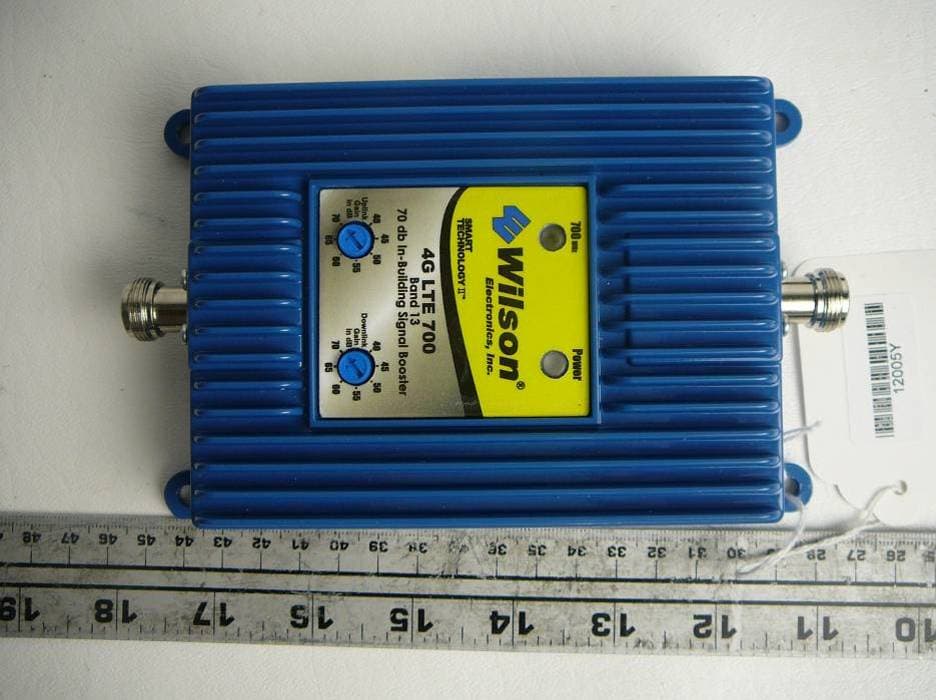
Click to zoom
Application Details
- Equipment Class
- TNB - Licensed Non-Broadcast Station Transmitter
- Date of Grant
- Aug 22, 2011
- Application Purpose
- Original Equipment
- Date of Application
- Aug 22, 2011
- Equipment Note
- LTE Signal Booster
- Frequency Range
- 776.00000000 - 787.00000000
- Company
- Wilson Electronics, LLC
- Country
- United States
Documents & Files
Document Text
Text extracted from the exhibit documents filed with the FCC. Open a document above to read the original.
Users Manual
Wilson ® Electronics, Inc. Contents: Antenna Options & Accessories . . . . . . . . . . . . . . . . . . .1 Quick Install Overview . . . . . . . . . . . . . . . . . . . . . . . . . . .2 Installation Diagram . . . . . . . . . . . . . . . . . . . . . . . . . . . . .3 Before Getting Started . . . . . . . . . . . . . . . . . . . . . . . . . . .4 Outside Antenna Installation . . . . . . . . . . . . . . . . . . . . . .6 Installing the Inside Antenna . . . . . . . . . . . . . . . . . . . . . .8 Installing a Wilson Electronics Signal Booster . . . . . . . . . 9 Powering up a Wilson Electronics Signal Booster . . . . .10 Finding the Strongest Signal . . . . . . . . . . . . . . . . . . . . .11 Understanding the Signal Booster Lights . . . . . . . . . . .13 Warnings and Recommendations . . . . . . . . . . . . . . . . .15 Guarantee & Warranty . . . . . . . . . . . . . . . . . . . . . . . . . .17 Specifications . . . . . . . . . . . . . . . . . . . . . . . . .Back Cover Note: This manual contains important safety and operating information . Please read and follow the instructions in this manual . Failure to do so could be hazardous and result in damage to your Signal Booster . 4G LTE 700 Band 13, 70 dB Adjustable Gain In-Building Wireless 700 MHz Smart Technology ™ Signal Booster 1 Contact Wilson Electronics Technical Support Team with any questions at 866-294-1660 or email: [email protected]. Hours: 7 am to 6 pm MST. 2 Installation Instructions for the Following Wilson Electronics Signal Booster: 4G LTE 700 Band 13, 70 dB Adjustable Gain In-Building Wireless 700MHz Smart Technology ™ Signal Booster Model # 271865 FCC ID: PWO271865 How it Works Wilson Electronics Signal Boosters are bi-directional devices that deliver service levels consistent with what would be expected in areas of high cell network coverage . They amplify a weak or shadowed signal in mobile, marine, M2M and in-building applications . When using a Wilson Electronics Signal Booster in conjunction with Wilson Electronics antennas, the Outside Antenna will collect the cell tower signal and send it through the cable to the Signal Booster . The signal is then amplified and re-transmitted through the Inside Antenna into the room . Cell phones and cellular data cards in that area then communicate with the improved signal . When a cell phone or cellular device transmits, the signal is received by the Inside Antenna, amplified by the Signal Booster and broadcasted back to the cell tower through the Outside Antenna . Inside this Package Signal Booster AC/DC Power Supply To purchase, call Wilson Electronics Sales Department at: 800-204-4104 Outdoor Antenna Options Indoor Antenna Options & Accessories 1 . Yagi Antenna (301111) 2 . Wide Band Directional Antenna 700 MHz - 2700 MHz (304411) 3 . Wide Band Panel Antenna 700-2700 MHz (301157) A . Wide-Band Panel Antenna 700-2700MHz (301134 & 301135) B . 50 Ohm Lightning Surge Protector with N-Connector (859902) Splitter options on page 9 2 1 B A 3 Note: Kits may contain different accessories 1 2 Contact Wilson Electronics Technical Support Team with any questions at 866-294-1660 or email: [email protected]. Hours: 7 am to 6 pm MST. Select a location to install the Signal Booster that is away 1 . from excessive heat, direct sunlight, moisture and has proper ventilation . Do not place the Signal Booster in an air-tight enclosure . Select a location on the roof of the building to install the Outside 2 . Antenna . Use a cell phone in test mode to find the strongest signal from the cell tower . Visit www.WilsonElectronics.com to find test mode function for your particular cell phone (see page 11) . Run the Outside Antenna cable to the Signal Booster and 3 . attach it to the connector labeled “Outside Antenna” on the Signal Booster . Run the Inside Antenna cable to the Signal Booster and attach it to the connector labeled “Inside Antenna” on the Signal Booster (see page 7 for more information on running cable) . Lightning Surge Protection is recommended for all in-building installations (see page 6) . Select a location for the Inside Antenna, preferably in the 4 . center of where the signal needs to be amplified . A minimum separation distance (combined vertical/horizontal) of 20 feet is necessary for operation (see page 8) . If the inside coverage is not sufficient you may need as much as 50 feet of separation . See installation diagram on pages 3 & 4 . Before powering up the Signal Booster, verify that both the 5 . Outside Antenna and the Inside Antenna are connected and check that all connections are tight . Note: Be careful when plugging the connectors in so as not to bend the center pins on the connectors. The Signal Booster has been packaged with the gain control 6 . knobs adjusted to the highest gain position . If the 700 MHz light is not green, please refer to pages 13 & 14 . Warning: 7. Connecting the Signal Booster directly to a cell phone with use of an adapter may damage the cell phone and the Signal Booster . Quick Install Overview See Installation Diagram on page 3 . Contact Wilson Electronics Technical Support Team with any questions at 866-294-1660 . 3 Contact Wilson Electronics Technical Support Team with any questions at 866-294-1660 or email: [email protected]. Hours: 7 am to 6 pm MST. 4 Typical Installation Outside Antenna Inside Antenna Installation Diagram Note: The Inside Antenna may be mounted on the wall directly under the Outside Antenna, in the null zone, if 15 feet of vertical separation can be maintained. Inside Antenna Preferred Method: Place the Inside Antenna in the ceiling facing down for the best coverage . Note: A Lightning Surge Protector is recommended for all building installations. Make sure the protector is installed in line between the Outside Antenna and the Signal Booster. (Optional second antenna for additional coverage). Null Zone: The area under the Outside Antenna, where the antenna radiates the least . 3 4 Contact Wilson Electronics T…
Text truncated - open the document above for the full version.
Attestation Statements
1274 Anvilwood Ave., Sunnyvale, CA 94089, USA Tel: (408) 732-9162 (Ext.3038), Fax: (408) 732-9164, http://baclcorp.com January 9, 2012 FEDERAL COMMUNICATIONS COMMISSIONS Authorization and Evaluation Division 7435 Oakland Mills Road Columbia, MD 21046 RE: Attestation Letter Dear Sir/Madam, Regarding Wilson FCC ID: PWO271865 granted on 2011-08-23; we would like to supersede the label drawing and External photos exhibits to remove the IC certification number as IC certification will not be pursued for this product. The Grant notes will also be updated to correct the antenna separation distance. Thank you very much Sincerely, Jennifer Paigly, Document Control Lead Document Control Department Bay Area Compliance Laboratories Corp. 1274 Anvilwood Ave. Sunnyvale, CA 94089, USA Tel: (408) 732-9162 (Ext. 3038) Fax: (408) 732-9164 Email: [email protected]
Attestation Statements
December 28, 2011 FEDERAL COMMUNICATIONS COMMISSIONS Authorization and Evaluation Division 7435 Oakland Mills Road Columbia, MD 21046 RE: Attestation Letter Dear Sir/Madam: Regarding our signal booster, FCC ID: PWO271865 granted on 2011-08-23, we would like to supersede the label drawing, external photo exhibits, and User Manual to remove references to IC since Industry Canada certification will not be pursued at this time. The Grant notes will also be updated to correct the antenna separation distance. Thank you. Sincerely, Richard M. Kline Senior Electrical Engineer
Attestation Statements
April 10, 2012 To: Tim Harrington FCC Equipment Authorization Branch Subject: FCC ID: PWO271865, Correspondence 121333 Items 1 and 2 in the subject correspondence are being addressed by BACL who is the test lab and TCB for the subject application. Our response to the additional items follows: 3) The attached MPE calculations have been revised as requested. Please note that the power levels in the originally submitted MPE calculations were higher and therefore more conservative than required by the FCC since they were based upon higher average power resulting from multiple signal calculations required by Industry Canada. 4) We have deleted all notes in our MPE calculations. These were previously included to give guidance to our engineering staff when preparing these documents. They were only applied as applicable to the specific analysis, but since they have caused confusion, we’ve deleted them and now keep them in a separate document. 5) The MPE calculations have been revised to only reference distances at 20 cm or greater. We will use the same (new) format for future applications. 6) The format of the MPE report has been changed to show the power density levels as requested. 7) The downlink output powers vs. number of carriers are listed since this was requested by Industry Canada. This is covered in paragraph 6.2 of IC Standard RSS-131, Zone Enhancers for the Land Mobile Service. IC requested in separate communications to include a detailed listing such as that which is included in the specification sheet of our Users Manual. Their concern was that (especially in an urban environment) it would be possible for the booster to receive more than one strong base station signal, and that this could cause overloading in the downlink output that could generate excessive spurious signals. As a result, the spurious signals so generated could interfere with downlink reception by other subscribers. Although not an FCC requirement, we don’t believe that inclusion of this data conflicts with any FCC rules, KDB instructions, etc. If anything further is required regarding the above, please do not hesitate to contact the undersigned. Sincerely, Richard (Riki) Kline Senior Electrical Engineer
Cover Letter(s)
July 19, 2011 Federal Communications Commission 7435 Oakland Mills Road Columbia, MD 21046 Subject: Data Confidentiality Gentlemen: Wilson Electronics, Inc. respectfully requests confidentiality of certain documentation provided with the submission of our model 271865 signal booster under FCC ID: PWO271865 in accordance with sections 0.457 and 0.459 of the Commission’s regulations. We request that the following documents be kept confidential: 1. Schematic Diagram and Parts List (4 pages), filename: 271865 Schematic & Parts List.pdf 2. Operational Description, filename: 271865 Operational Description.pdf 3. Block Diagram, filename: 271865 Block Diagram.pdf The above material is confidential and contains proprietary trade secrets and technical data which must be kept from competitors. Public access to these items could result in duplication of our circuitry and/or techniques thereby reducing our competitive advantage and causing us severe damage. Sincerely, Richard M. Kline Senior Electrical Engineer
External Photos
Wilson Electronics, Inc. FCC ID: PWO271865 Report Number: R1106171-27 Page 85 of 90 FCC Part 27 Test Report 14 EXHIBIT C - EUT PHOTOGRAPHS 14.1 EUT - Top View 14.2 EUT - Side View 1 Wilson Electronics, Inc. FCC ID: PWO271865 Report Number: R1106171-27 Page 86 of 90 FCC Part 27 Test Report 14.3 EUT - Side View 2 14.4 EUT – Inside Antenna Port View Wilson Electronics, Inc. FCC ID: PWO271865 Report Number: R1106171-27 Page 87 of 90 FCC Part 27 Test Report 14.5 EUT – Outside Antenna Port View 14.6 EUT - Bottom View
ID Label/Location Info
Wilson Electronics, Inc. FCC ID: PWO271865 Report Number: R1106171-27 Page 82 of 90 FCC Part 27 Test Report 12 EXHIBIT A - FCC ID LABEL REQUIREMENTS 12.1 FCC ID Label Requirement FCC §2.925 Identification of equipment (a) Each equipment covered in an application for equipment authorization shall bear a nameplate or label listing the following: (1) FCC Identifier consisting of the two elements in the exact order specified in §2.926. The FCC Identifier shall be preceded by the term FCC ID in capital letters on a single line, and shall be of a type size large enough to be legible without the aid of magnification. Example: FCC ID: XXX123 Where: XXX—Grantee Code, 123—Equipment Product Code 12.2 FCC ID Label Contents 12.3 FCC Label Location on EUT Label here
Internal Photos
Wilson Electronics, Inc. FCC ID: PWO271865 Report Number: R1106171-27 Page 88 of 90 FCC Part 27 Test Report 14.7 EUT – Cover off View 14.8 EUT – Cover off Close up View Wilson Electronics, Inc. FCC ID: PWO271865 Report Number: R1106171-27 Page 89 of 90 FCC Part 27 Test Report 14.9 EUT – Main PCB Board Front View 14.10 EUT – Main PCB Board Rear View Wilson Electronics, Inc. FCC ID: PWO271865 Report Number: R1106171-27 Page 90 of 90 FCC Part 27 Test Report 14.11 AC/DC Power Supply View ***** End of Report *****
RF Exposure Info
Minimum Safe Distance From Antennas Based upon FCC OET Bulletin 65 and other FCC Sources INPUT DATA Frequency MHz776 Pout Watts0.73600 Duty Cycle Percent100.0% Ant. Gain dBi10.00 Coax Loss dB0.00 Evaluation Distance From Antenna In cm34.0 Ant. Gain less Coax Loss dBi10.00 Evalluation Distance From Antenna In Inches13.39 ERP (Watts)4.4878 EIRP (Watts)7.3600 FCC Limit at Above Frequency (mw/cm 2 ) 0.52 Calculated Power Density With Above Input Data (mw/cm 2 ) 0.51 REFERENCE DATA Pout dBm28.67 Antenna Gain (non-log)10.00 Coax loss (non-log)1.00 General FCC Limit (mw/cm 2 ) f/1500 For Amplifier Model Number: Frequency Band (MHz) Mobile or Fixed? Outside or Inside Antenna? Antenna Type: Safe Distance (inches): Signature: Date:April 6, 2012 cable loss does not exceed 10 dBi 776 - 787 MHz (Uplink) RESULTS OF CALCULATIONS SUMMARY FOR PUBLICATION 271865 Fixed Any antenna whose gain less Outside 14 inches 4/6/2012, 2:29 PM271865 Revised MPE Uplink.xlsx
RF Exposure Info
Minimum Safe Distance From Antennas Based upon FCC OET Bulletin 65 and other FCC Sources INPUT DATA Frequency MHz746 Pout Watts0.35560 Duty Cycle Percent100.0% Ant. Gain dBi7.60 Coax Loss dB0.00 Evaluation Distance From Antenna In cm20.0 Ant. Gain less Coax Loss dBi7.60 Evalluation Distance From Antenna In Inches7.87 ERP (Watts)1.2477 EIRP (Watts)2.0463 FCC Limit at Above Frequency (mw/cm 2 ) 0.50 Calculated Power Density With Above Input Data (mw/cm 2 ) 0.41 REFERENCE DATA Pout dBm25.51 Antenna Gain (non-log)5.75 Coax loss (non-log)1.00 General FCC Limit (mw/cm 2 ) f/1500 For Amplifier Model Number: Frequency Band (MHz) Mobile or Fixed? Outside or Inside Antenna? Antenna Type: Safe Distance (inches): Signature: Date:April 6, 2012 cable loss does not exceed 7.6 dBi 746 - 757 MHz (Downlink) RESULTS OF CALCULATIONS SUMMARY FOR PUBLICATION 271865 Fixed Any antenna whose gain less Inside 8 inches 4/6/2012, 2:28 PM271865 Revised MPE Downlink.xlsx
Test Report
Note: This test report is prepared for the customer shown above and for the device described herein. It may not be duplicated or used in part without prior written consent from Bay Area Compliance Laboratories Corp. This report must not be used by the customer to claim product certification, approval, or endorsement by NVLAP*, NIST, or any agency of the Federal Government. * This report may contain data that are not covered by the NVLAP accreditation and are marked with an asterisk “*” (Rev.2) FCC PART 27 TEST AND MEASUREMENT REPORT For Wilson Electronics, Inc. 3301 East Deseret Drive, St. George, Utah 84790, USA FCC ID: PWO271865 Model: 271865 Report Type: Original Report Product Type: LTE Signal Booster Test Engineer: Quinn Jiang Report Number: R1106171-27 Report Date: 2011-08-16 Reviewed By: Victor Zhang EMC/RF Lead Prepared By: (91) Bay Area Compliance Laboratories Corp. 1274 Anvilwood Avenue, Sunnyvale, CA 94089, USA Tel: (408) 732-9162 Fax: (408) 732 9164 Wilson Electronics, Inc. FCC ID: PWO271865 Report Number: R1106171-27 Page 2 of 90 FCC Part 27 Test Report TABLE OF CONTENTS 1 GENERAL INFORMATION ............................................................................................................................... 5 1.1 PRODUCT DESCRIPTION FOR EQUIPMENT UNDER TEST (EUT)........................................................................... 5 1.2 MECHANICAL DESCRIPTION.............................................................................................................................. 5 1.3 OBJECTIVE......................................................................................................................................................... 5 1.4 RELATED SUBMITTAL(S)/GRANT(S)................................................................................................................... 5 1.5 TEST METHODOLOGY........................................................................................................................................ 6 1.6 MEASUREMENT UNCERTAINTY.......................................................................................................................... 6 1.7 TEST FACILITY................................................................................................................................................... 6 2 SYSTEM TEST CONFIGURATION .................................................................................................................. 7 2.1 JUSTIFICATION................................................................................................................................................... 7 2.2 EUT EXERCISE SOFTWARE................................................................................................................................7 2.3 EQUIPMENT MODIFICATIONS............................................................................................................................. 7 2.4 LOCAL SUPPORT EQUIPMENT AND SOFTWARE LIST AND DETAILS.................................................................... 7 2.5 INTERNAL CONFIGURATIONS OF EUT................................................................................................................ 7 1.8 EUT POWER SUPPLY INFORMATION.................................................................................................................. 7 2.6 INTERFACE PORTS AND CABLES........................................................................................................................ 8 2.7 TEST SETUP BLOCK DIAGRAM........................................................................................................................... 8 3 SUMMARY OF TEST RESULTS...................................................................................................................... 10 4 FCC §2.1046 & §27.50 – RF OUTPUT POWER............................................................................................... 11 4.1 APPLICABLE STANDARD.................................................................................................................................. 11 4.2 TEST PROCEDURE............................................................................................................................................ 11 4.3 TEST ENVIRONMENTAL CONDITIONS............................................................................................................... 11 4.4 TEST EQUIPMENT LIST AND DETAILS.............................................................................................................. 11 4.5 TEST RESULTS................................................................................................................................................. 12 5 FCC §2.1047 - MODULATION CHARACTERISTIC..................................................................................... 14 5.1 APPLICABLE STANDARD.................................................................................................................................. 14 5.2 TEST RESULT................................................................................................................................................... 14 6 FCC §2.1049 & §27.53 - OCCUPIED BANDWIDTH ......................................................................................15 6.1 APPLICABLE STANDARD.................................................................................................................................. 15 6.2 TEST PROCEDURE............................................................................................................................................ 15 6.3 TEST ENVIRONMENTAL CONDITIONS............................................................................................................... 15 6.4 TEST EQUIPMENT LIST AND DETAILS.............................................................................................................. 15 6.5 TEST RESULTS......................…
Text truncated - open the document above for the full version.
Test Setup Photos
Wilson Electronics, Inc. FCC ID: PWO271865 Report Number: R1106171-27 Page 83 of 90 FCC Part 27 Test Report 13 EXHIBIT B - TEST SETUP PHOTOGRAPHS 13.1 Radiated Emissions - Front View 13.2 Radiated Emissions 30 MHz to 1 GHz- Rear View Wilson Electronics, Inc. FCC ID: PWO271865 Report Number: R1106171-27 Page 84 of 90 FCC Part 27 Test Report 13.3 Radiated Emissions above 1 GHz- Rear View 13.4 Conducted Measurement View
Contact Information
Applicant
Mikel Parry(Compliance Manager)
Test Firm
Bay Area Compliance LaboratoryJohn Chan
Technical Specifications
| # | Rule Parts | Frequency Range | Power Output | Emission | Tolerance |
|---|---|---|---|---|---|
| 2 | 27 | 776 MHz - 787 MHz | 741.00 mW | D7W | Amp |
Other Applications from Wilson Electronics, LLC
PWO086
Mar 09, 2026Single Band Bi-Directional Amplifier
Equipment Class
B2W - Part 20 Wideband Consumer Booster (CMRS)PWO072
Aug 26, 20245G NR Industrial Signal Booster
Equipment Class
B2I - Part 20 Industrial Booster (CMRS)
PWO075
Jan 10, 2024Quint Band Signal Booster
Equipment Class
B2W - Part 20 Wideband Consumer Booster (CMRS)
PWO460065
Nov 04, 2020Dual Band Signal Booster
Equipment Class
B2W - Part 20 Wideband Consumer Booster (CMRS)
PWO460061
Sep 22, 2020Quint Band Signal Booster
Equipment Class
B2W - Part 20 Wideband Consumer Booster (CMRS)