PWO2B1216Dual Band High Power Direct Connect Signal Booster
Wilson Electronics, LLC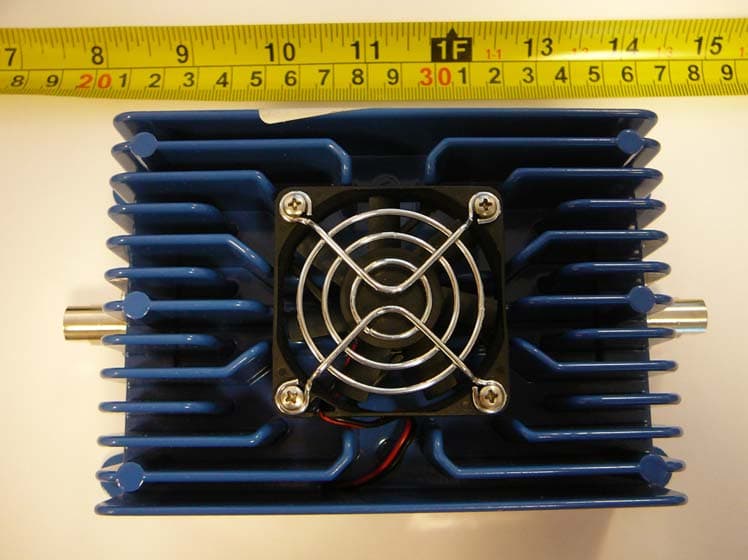
Click to zoom
Application Details
- Equipment Class
- PCB - PCS Licensed Transmitter
- Date of Grant
- Jul 03, 2012
- Application Purpose
- Original Equipment
- Date of Application
- Jul 03, 2012
- Equipment Note
- Dual Band High Power Direct Connect Signal Booster
- Frequency Range
- 1850.00000000 - 1910.00000000
- Company
- Wilson Electronics, LLC
- Country
- United States
Documents & Files
Document Text
Text extracted from the exhibit documents filed with the FCC. Open a document above to read the original.
Users Manual
Contents Before Getting Started . . . . . . . . . . . . . . . . . . . . . . . . . . . .1 Accessories and Antenna Options . . . . . . . . . . . . . . . . . . 1 Quick Installation Overview . . . . . . . . . . . . . . . . . . . . . . . .2 Installation Diagram . . . . . . . . . . . . . . . . . . . . . . . . . . . . . .2 Installing the External Adapter . . . . . . . . . . . . . . . . . . . . . .3 Installing the Outside Antenna . . . . . . . . . . . . . . . . . . . . . .3 Installing a Wilson Electronics Signal Booster . . . . . . . . . .3 Powering Up a Wilson Electronics Signal Booster . . . . . . 3 In-Building Installation . . . . . . . . . . . . . . . . . . . . . . . . . . . .4 Warnings and Recommendations . . . . . . . . . . . . . . . . . . .5 Guarantee and Warranty . . . . . . . . . . . . . . . . . . . . . . . . . .6 Signal Booster Specifications . . . . . . . . . . . . . .Back Cover GSM High Power Direct Connect 800/1900 MHz Smart Technology ™ Signal Booster Note: This manual contains important safety and operating information . Please read and follow the instructions in this manual . Failure to do so could be hazardous and result in damage to your Signal Booster . Appearance of device and accessories may vary . 1 Contact Wilson Electronics Technical Support Team with any questions at 866-294-1660 or email: [email protected] Mon.- Fri. Hours: 7 am to 6 pm MST. 2 Inside this Package Accessories & Antenna Options (sold separately) Before Getting Started This guide will help you properly install your Wilson Electronics Signal Booster . It is impor- tant to read through all of the installation steps for your particular application prior to installing any equipment. Read through the instructions, visualize where all the equipment will need to be installed and do a soft installation before mounting any equipment . For further assistance please call our Wilson Electronics Technical Support Team: 866-294-1660 . Installation Instructions for the Following Wilson Electronics Signal Booster: Model # 2B1216 FCC: PWO2B1216 IC:4726A-2B1216 The term “IC” before the radio certification number only signifies that Industry Canada technical specifications were met . NMO Mount (301104) Magnet Mount (301125) Trucker Mount (301101) Mini Magnet (301126) 800/1900 MHz Omni- Directional Antenna (301202) Lightning Surge Protector (859902) Marine Antenna (301130) 700/2700 MHz Wide-Band Directional Antenna (304475) Wide Band Directional Antenna (adapters may be required) Omni Directional Antennas (adapters may be required) 7V AC/DC Power Supply (859986) GSM High Power Signal Booster 6’ RG174 Cable (951141) Accessory (adapters may be required) Appearance of device and accessories may vary . 12 Contact Wilson Electronics Technical Support Team with any questions at 866-294-1660 or email: [email protected] Mon.- Fri. Hours: 7 am to 6 pm MST. Select a location to install the Signal Booster that is away from excessive heat, direct 1 . sunlight, moisture and that has proper ventilation . Do not place the Signal Booster in an air-tight enclosure . Select a location on the top of the structure to install the Outside Antenna . Use a cell 2 . phone in test mode to find the strongest signal from the cell tower . Visit www.WilsonElectronics.com to find test mode function for your particular cell phone . Run the Outside Antenna cable to the Signal Booster and attach it to the connector 3 . labeled “Outside Antenna .” An external adapter is required to connect the cell phone or cellular data card to the 4 . Signal Booster . The external adapter plugs into the included antenna extension cable and directly into a socket on the cellular device . Run the extension cable from the external adapter and attach it to the connector labeled “Inside Antenna” on the Signal Booster . Note: Be careful when plugging the connector in so as not to bend the center pins on the connectors. Ensure all cables have a tight connection. Before powering up the Signal Booster verify that both the Outside Antenna and the 5 . Inside Antenna are connected and check that all connections are tight . An AC surge protector is recommended for all installations (not included) . Quick Installation Overview The following steps provide a summary of the Signal Booster/antenna installation process . Contact Wilson Electronics Technical Support Team with any questions at 866-294-1660 . Powerstrip Surge Protector Power Supply GSM Hi-Power Signal Booster Cellular Modem Mini-Magnet Antenna Installation Diagram (Figure 1) NOTE: It is very important to power your Signal Booster using a surge protected AC Power Strip with at least a 1000 Joule rating. Failure to do this will void your warranty in the event of a power surge or lightning strike. 3 Contact Wilson Electronics Technical Support Team with any questions at 866-294-1660 or email: [email protected] Mon.- Fri. Hours: 7 am to 6 pm MST. 4 How it Works Wilson Electronics Signal Boosters are bi-directional devices that deliver service levels consistent with what would be expected in areas of high cell network coverage . They amplify a weak or shadowed signal in mobile, marine, M2M and in-building applications . When using a Wilson Electronics Signal Booster in conjunction with Wilson Electronics antennas, the Outside Antenna will collect the cell tower signal and send it through the cable to the Signal Booster . Cell phones and cellular data cards then communicate with the improved signal . When a cellular device transmits, the signal is amplified by the Signal Booster and transmitted back to the cell tower through the Outside Antenna . Installing the External Adapter An external adapter is required to connect the cell phone or cellular data card to the Signal Booster. The external adapter is cell phone/data card-specific and may be purchased through a local retailer . Refer to Wilson Electronics Adapter Guide to identify the correct adapter for your cell phone or cellular data card . The adapter gu…
Text truncated - open the document above for the full version.
Cover Letter(s)
FCC Confidential Authorization May 8, 2012 FEDERAL COMMUNICATIONS COMMISSIONS Authorization and Evaluation Division 7435 Oakland Mills Road Columbia, MD 21046 Subject: Confidentiality Request regarding application for certification of FCC ID: PWO2B1216 In accordance with Sections 0.457 and 0.459 of the Commission’s Rules, Wilson Electronics, Inc., hereby requests long-term confidential treatment of information accompanying this application as outlined below: • Block Diagram, filename: 2B1216 Block Diagram.pdf • Schematic Diagram and Parts List, filename: 2B1216 Schematic & Parts List.pdf • Operational Description, filename: 2B1216 Operational Description.pdf The above materials contain proprietary and confidential information not customarily released to the public. The public disclosure of these materials provides unjustified benefits to its competitors in the market. Sincerely, Patrick L. Cook Senior Research and Development Engineer Wilson Electronics, Inc. 3301 E. Deseret Dr. St. George, UT 84790 Tel: (435)673-5021, ext. 124 mobile: (435)705-4386 E-mail: [email protected]
External Photos
Wilson Electronics, Inc. FCC ID: PWO2B1216 Report Number: R1110063-2224 Page 97 of 101 FCC Part 22H/24E Test Report 13 EXHIBIT C – EUT PHOTOGRAPHS 13.1 EUT - Top View 13.2 EUT - Bottom View Wilson Electronics, Inc. FCC ID: PWO2B1216 Report Number: R1110063-2224 Page 98 of 101 FCC Part 22H/24E Test Report 13.3 EUT - Side View (1) 13.4 EUT - Side View (2) Wilson Electronics, Inc. FCC ID: PWO2B1216 Report Number: R1110063-2224 Page 99 of 101 FCC Part 22H/24E Test Report 13.5 EUT – Outside Antenna Port View 13.6 EUT – Inside Antenna Port View
ID Label/Location Info
Wilson Electronics, Inc. FCC ID: PWO2B1216 Report Number: R1110063-2224 Page 94 of 101 FCC Part 22H/24E Test Report 11 EXHIBIT A - FCC ID LABELING REQUIREMENTS 11.1 FCC ID Label Requirements FCC §2.925 Identification of equipment (a) Each equipment covered in an application for equipment authorization shall bear a nameplate or label listing the following: (1) FCC Identifier consisting of the two elements in the exact order specified in §2.926. The FCC Identifier shall be preceded by the term FCC ID in capital letters on a single line, and shall be of a type size large enough to be legible without the aid of magnification. Example: FCC ID: XXX123 Where: XXX—Grantee Code, 123—Equipment Product Code 11.2 FCC ID Label and Location
Internal Photos
Wilson Electronics, Inc. FCC ID: PWO2B1216 Report Number: R1110063-2224 Page 100 of 101 FCC Part 22H/24E Test Report 13.7 EUT – Top without Cover View 13.8 EUT – PCB Board Assembly Top View Wilson Electronics, Inc. FCC ID: PWO2B1216 Report Number: R1110063-2224 Page 101 of 101 FCC Part 22H/24E Test Report 13.9 EUT – PCB Board Assembly Bottom View --- END OF REPORT ---
Test Report
Note: This test report is prepared for the customer shown above and for the device described herein. It may not be duplicated or used in part without prior written consent from Bay Area Compliance Laboratories Corp. This report must not be used by the customer to claim product certification, approval, or endorsement by A2LA* or any agency of the Federal Government. * This report may contain data that are not covered by the A2LA accreditation and are marked with an asterisk “*” FCC PART 22H, 24E TEST AND MEASUREMENT REPORT For Wilson Electronics, Inc. 3301 East Deseret Drive, St. George, Utah 84790, USA FCC ID: PWO2B1216 Model: 2B1216 Report Type: Original Report Product Type: Dual Band Signal Booster Test Engineer: Lionel Lara Report Number: R1110063-2224 Report Date: 2012-06-27 Reviewed By: Victor Zhang RF/EMC Engineer, Lead Bay Area Compliance Laboratories Corp. 1274 Anvilwood Avenue, Sunnyvale, CA 94089, USA Tel: (408) 732-9162 Fax: (408) 732 9164 Wilson Electronics, Inc. FCC ID: PWO2B1216 Report Number: R1110063-2224 Page 2 of 101 FCC Part 22H/24E Test Report TABLE OF CONTENTS 1 GENERAL INFORMATION ............................................................................................................................... 5 1.1 PRODUCT DESCRIPTION FOR EQUIPMENT UNDER TEST (EUT)........................................................................... 5 1.2 MECHANICAL DESCRIPTION.............................................................................................................................. 5 1.3 OBJECTIVE......................................................................................................................................................... 5 1.4 RELATED SUBMITTAL(S)/GRANT(S)................................................................................................................... 5 1.5 TEST METHODOLOGY........................................................................................................................................ 5 1.6 MEASUREMENT UNCERTAINTY.......................................................................................................................... 6 1.7 TEST FACILITY................................................................................................................................................... 6 2 SYSTEM TEST CONFIGURATION .................................................................................................................. 7 2.1 JUSTIFICATION................................................................................................................................................... 7 2.2 EUT EXERCISE SOFTWARE................................................................................................................................7 2.3 EQUIPMENT MODIFICATIONS............................................................................................................................. 7 2.4 POWER SUPPLY AND LINE FILTERS.................................................................................................................... 7 2.5 EUT INTERNAL CONFIGURATION...................................................................................................................... 7 2.6 LOCAL SUPPORT EQUIPMENT LIST AND DETAILS.............................................................................................. 7 2.7 INTERFACE PORTS AND CABLING...................................................................................................................... 8 3 SUMMARY OF TEST RESULTS........................................................................................................................ 9 4 FCC §2.1046, §22.913(A) & §24.232 – RF OUTPUT POWER ........................................................................ 10 4.1 APPLICABLE STANDARD.................................................................................................................................. 10 4.2 TEST PROCEDURE............................................................................................................................................ 10 4.3 TEST ENVIRONMENTAL CONDITIONS............................................................................................................... 10 4.4 TEST EQUIPMENT LIST AND DETAILS.............................................................................................................. 10 4.5 TEST RESULTS................................................................................................................................................. 11 5 FCC §2.1047 - MODULATION CHARACTERISTIC..................................................................................... 13 5.1 APPLICABLE STANDARD.................................................................................................................................. 13 5.2 TEST RESULT................................................................................................................................................... 13 6 FCC §2.1049, §22.917 & §24.238 - OCCUPIED BANDWIDTH...................................................................... 14 6.1 APPLICABLE STANDARD.................................................................................................................................. 14 6.2 TEST PROCEDURE............................................................................................................................................ 14 6.3 TEST ENVIRONMENTAL CONDITIONS............................................................................................................... 14 6.4 TEST EQUIPMENT LIST AND DETAILS.............................................................................................................. 14 6.5 TEST RESULTS................................................................................................................................................. 15 7 FCC §2.1053, §22.917 & §2…
Text truncated - open the document above for the full version.
Test Setup Photos
Wilson Electronics, Inc. FCC ID: PWO2B1216 Report Number: R1110063-2224 Page 95 of 101 FCC Part 22H/24E Test Report 12 EXHIBIT B - TEST SETUP PHOTOGRAPHS 12.1 Radiated Emissions - Front View 12.2 Radiated Emissions - Rear View (Below 1 GHz) Wilson Electronics, Inc. FCC ID: PWO2B1216 Report Number: R1110063-2224 Page 96 of 101 FCC Part 22H/24E Test Report 12.3 Radiated Emissions - Rear View (Above 1 GHz)
Contact Information
Applicant
Mikel Parry(Compliance Manager)
Test Firm
Bay Area Compliance LaboratoryJohn Chan
Technical Specifications
| # | Rule Parts | Frequency Range | Power Output | Emission | Tolerance |
|---|---|---|---|---|---|
| 15 | 24E | 1.85 GHz - 1.91 GHz | 2.344 W | F9W | Amp |
Other Applications from Wilson Electronics, LLC
PWO086
Mar 09, 2026Single Band Bi-Directional Amplifier
Equipment Class
B2W - Part 20 Wideband Consumer Booster (CMRS)PWO072
Aug 26, 20245G NR Industrial Signal Booster
Equipment Class
B2I - Part 20 Industrial Booster (CMRS)
PWO075
Jan 10, 2024Quint Band Signal Booster
Equipment Class
B2W - Part 20 Wideband Consumer Booster (CMRS)
PWO460065
Nov 04, 2020Dual Band Signal Booster
Equipment Class
B2W - Part 20 Wideband Consumer Booster (CMRS)
PWO460061
Sep 22, 2020Quint Band Signal Booster
Equipment Class
B2W - Part 20 Wideband Consumer Booster (CMRS)