PWO460004Model 460004 Signal Booster
Wilson Electronics, LLC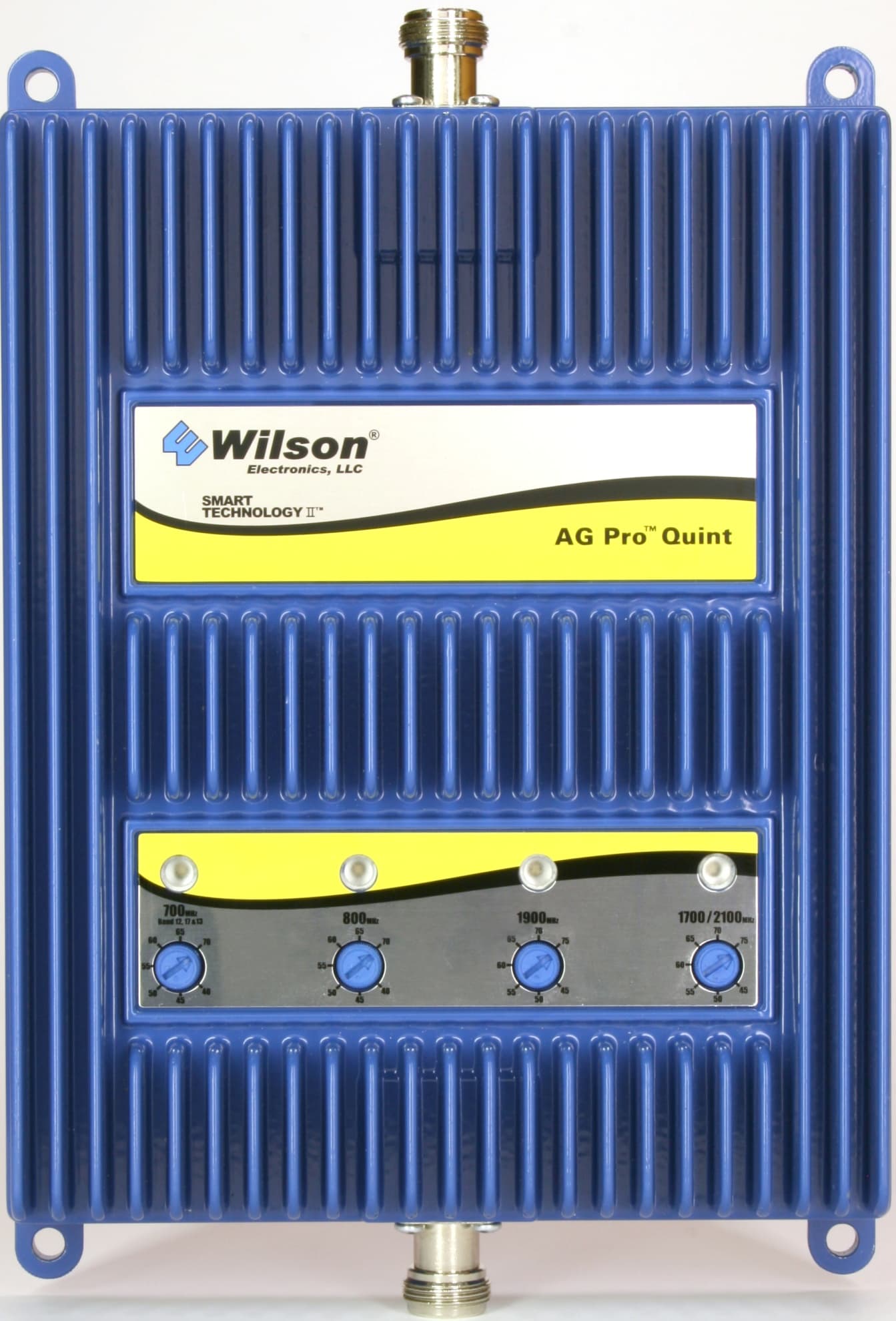
Click to zoom
Application Details
- Equipment Class
- B2W - Part 20 Wideband Consumer Booster (CMRS)
- Date of Grant
- Jan 23, 2014
- Application Purpose
- Original Equipment
- Date of Application
- Oct 21, 2013
- Equipment Note
- Model 460004 Signal Booster
- Frequency Range
- 2110.00000000 - 2155.00000000
- Company
- Wilson Electronics, LLC
- Country
- United States
Documents & Files
Document Text
Text extracted from the exhibit documents filed with the FCC. Open a document above to read the original.
Users Manual
Contents: Kit Configurations . . . . . . . . . . . . . . . . . . . . . . . . . . . . . . . . . . . . . . . . . . . . . . .1 Antenna Kit Options . . . . . . . . . . . . . . . . . . . . . . . . . . . . . . . . . . . . . . . . . . . . . .2 Installation Diagram . . . . . . . . . . . . . . . . . . . . . . . . . . . . . . . . . . . . . . . . . . . . . .3 Before Getting Started . . . . . . . . . . . . . . . . . . . . . . . . . . . . . . . . . . . . . . . . . . . .4 Quick Install Overview . . . . . . . . . . . . . . . . . . . . . . . . . . . . . . . . . . . . . . . . . . . .5 Installing the Outside Antenna . . . . . . . . . . . . . . . . . . . . . . . . . . . . . . . . . . . . . .6 Finding the Strongest Signal . . . . . . . . . . . . . . . . . . . . . . . . . . . . . . . . . . . . . . .7 Installing the Inside Antenna . . . . . . . . . . . . . . . . . . . . . . . . . . . . . . . . . . . . . . .9 Installing a Wilson Electronics Signal Booster . . . . . . . . . . . . . . . . . . . . . . . . . .9 Powering up a Wilson Electronics Signal Booster . . . . . . . . . . . . . . . . . . . . . .10 Understanding the Signal Booster Lights . . . . . . . . . . . . . . . . . . . . . . . . . . . .11 Warnings and Recommendations . . . . . . . . . . . . . . . . . . . . . . . . . . . . . . . . . .13 Guarantee & Warranty . . . . . . . . . . . . . . . . . . . . . . . . . . . . . . . . . . . . . . . . . . .14 Specifications . . . . . . . . . . . . . . . . . . . . . . . . . . . . . . . . . . . . . . . . .Back Cover Note: This manual contains important safety and operating information . Please read and follow the instructions in this manual . Failure to do so could be hazardous and result in damage to your Signal Booster . AG Pro Quint Appearance of device and accessories may vary . 700 / 800 / AWS (1700 / 2100) / 1900 MHz In-Building Wireless Smart Technology ™ Signal Booster 1 2 Contact Wilson Electronics Technical Support Team with any questions at 866-294-1660 or email: [email protected]. Mon.- Fri. Hours: 7 am to 6 pm MST. Installation Instructions for the Following Wilson Electronics Signal Boosters: How it Works Designed to provide signal coverage in buildings up to 80,000 square feet, the Wilson AG Pro Quint boosts signals on 800 MHz, 1900MHz, AWS and both AT&T and Verizon 700 MHz 4G networks as well as Sprint 4G on the G-Block of 1900 MHz . The AG Pro Quint is the most affordable five-band Signal Booster available . Wilson’s compact, integrated design is about the size of a textbook and weighs less than 3 pounds . The AG Pro Quint’s control knobs allow the installer to optimize the gain on each of the frequency bands . The AG Pro Quint delivers up to 69 .9 dB of gain and supports CDMA, GSM, EVDO, LTE, HSPA+ and WCDMA technologies . Like all Wilson Signal Boosters this unit features cell tower protection technologies refined over more than a decade of research and development . Kit Configurations AG Pro ™ Quint 700 / 800 / AWS (1700 / 2100) / 1900 MHz In-Building Wireless Smart Technology ™ Signal Booster Model # 460004 FCC ID: PWO460004 Inside Antenna Options Kit 309900-50N • 2- Wall Panel antennas • 1- 50 ohm 3-Way Splitter Kit 309905-50N • 3 - Wall Panel Antennas • 3 - 2-Way 50 Ohm Splitters Kit 309902-75F • 2 - Wall Panel Antennas • 1 - 3-Way 75 Ohm Splitter Kit 309903-75F • 3 - Wall Panel Antennas • 3 - 2-Way 75Ohm Splitters Kit 309904-75F • 1 – Wall Panel Antenna • 1- 2-Way 75 Ohm Splitter Kit 301121-40010 • 50 Ohm Dome Antenna • 10’ LMR400 Kit 301151-0610 • 75 Ohm Dome Antenna • 10’ RG6 Cable 311155-0630 • 75 Ohm Wall mount Panel Antenna • 30’ RG6 Cable 311135-5820 • 50 Ohm Wall mount Panel Antenna • 20’ RG58 Cable 311135-40060 • 50 Ohm Wall mount Panel Antenna • 60’ LMR400 Cable 311155-40060 • 75 Ohm Wall mount Panel Antenna • 60’ LMR400 Cable 1 2 Contact Wilson Electronics Technical Support Team with any questions at 866-294-1660 or email: [email protected]. Mon.- Fri. Hours: 7 am to 6 pm MST. To purchase, contact Wilson Electronics Sales Department at: 800-204-4104 Outside Antenna Options Kit 301111-0675 • Yagi Directional Antenna • 75’ RG6 Cable • N-Male to F-Female adapter Kit 311201-0620 • Omni Directional w/ F-Female • 20’ RG6 Cable Kit 311124-0660 • 1900 MHz Yagi Directional • 60’ RG6 Cable • N-Male to F-Female adapter Kit 311129-0650 • 800 MHz Yagi Directional • 50’ RG6 Cable • N-Male to F-Female adapter Kit 314473 -0640 • 75 Ohm Pole Mount Panel Antenna • 40’ RG6 Cable Kit 314475 – 0630 • 75 Ohm Wide Band Directional • 30’ RG6 Cable Kit 311141 - 0620 • 75 Ohm Grey Brick Antenna • 20’ RG6 Cable Kit 314411-40075 • 50 Ohm Wide Band Directional • 75’ LMR400 Cable Kit 311203-40020 • Omni-Directional Antenna • 20’ LMR400 Cable Kit 301111-400170 • Yagi Directional w/ N-Female • 170’ LMR400 Kit 311129-400100 • 800 MHz Yagi Antenna • 100’ LMR400 Cable Kit 314453-40075 • 50 Ohm Pole Mount Panel Antenna • 75’ LMR400 Cable Kit 314453-5825 • 50 Ohm Pole Mount Panel Antenna • 25’ RG58 Cable Kit 314411-5825 • 50 Ohm Wide Band Directional • 25’ RG58 Cable Kit 301111-5850 • Yagi Directional Antenna • 50’ RG58 Cable Kit 311124 – 5840 • 1900 MHz Yagi Directional • 40’ RG58 Cable Kit 311203-5820 • Omni-Directional Antenna • 20’ RG58 Cable Kit 311129-5830 • 800 MHz Yagi Antenna • 30’ RG58 Cable Mini-Mag - 301126 • 12.5 RG174 Cable 3 4 Contact Wilson Electronics Technical Support Team with any questions at 866-294-1660 or email: [email protected]. Mon.- Fri. Hours: 7 am to 6 pm MST. Typical Installation Outside Antenna (Wide Band Directional Antenna shown) Inside Antenna Power Supply Installation Diagram Inside Antenna Preferred Method: Place the Inside Antenna in the ceiling facing down for the best coverage . Note: A Lightning Surge Protector is recommended for all building installations (sold separately). Make sure the protector is installed in line between the Outside Antenna and the Signal Booster. Null Zone: The area under the Outside Antenna, where the Outside Antenna radiates the leas…
Text truncated - open the document above for the full version.
Users Manual
Contents: Kit Configurations . . . . . . . . . . . . . . . . . . . . . . . . . . . . . . . . . . . . . . . . . . . . . . .1 Antenna Kit Options . . . . . . . . . . . . . . . . . . . . . . . . . . . . . . . . . . . . . . . . . . . . . .2 Installation Diagram . . . . . . . . . . . . . . . . . . . . . . . . . . . . . . . . . . . . . . . . . . . . . .3 Before Getting Started . . . . . . . . . . . . . . . . . . . . . . . . . . . . . . . . . . . . . . . . . . . .4 Quick Install Overview . . . . . . . . . . . . . . . . . . . . . . . . . . . . . . . . . . . . . . . . . . . .5 Installing the Outside Antenna . . . . . . . . . . . . . . . . . . . . . . . . . . . . . . . . . . . . . .6 Finding the Strongest Signal . . . . . . . . . . . . . . . . . . . . . . . . . . . . . . . . . . . . . . .7 Installing the Inside Antenna . . . . . . . . . . . . . . . . . . . . . . . . . . . . . . . . . . . . . . .9 Installing a Wilson Electronics Signal Booster . . . . . . . . . . . . . . . . . . . . . . . . . .9 Powering up a Wilson Electronics Signal Booster . . . . . . . . . . . . . . . . . . . . . .10 Understanding the Signal Booster Lights . . . . . . . . . . . . . . . . . . . . . . . . . . . .11 Warnings and Recommendations . . . . . . . . . . . . . . . . . . . . . . . . . . . . . . . . . .13 Guarantee & Warranty . . . . . . . . . . . . . . . . . . . . . . . . . . . . . . . . . . . . . . . . . . .14 Specifications . . . . . . . . . . . . . . . . . . . . . . . . . . . . . . . . . . . . . . . . .Back Cover Note: This manual contains important safety and operating information . Please read and follow the instructions in this manual . Failure to do so could be hazardous and result in damage to your Signal Booster . AG Pro Quint Appearance of device and accessories may vary . 700 / 800 / AWS (1700 / 2100) / 1900 MHz In-Building Wireless Smart Technology ™ Signal Booster 1 2 Contact Wilson Electronics Technical Support Team with any questions at 866-294-1660 or email: [email protected]. Mon.- Fri. Hours: 7 am to 6 pm MST. Installation Instructions for the Following Wilson Electronics Signal Boosters: How it Works Designed to provide signal coverage in buildings up to 80,000 square feet, the Wilson AG Pro Quint boosts signals on 800 MHz, 1900MHz, AWS and both AT&T and Verizon 700 MHz 4G networks as well as Sprint 4G on the G-Block of 1900 MHz . The AG Pro Quint is the most affordable five-band Signal Booster available . Wilson’s compact, integrated design is about the size of a textbook and weighs less than 3 pounds . The AG Pro Quint’s control knobs allow the installer to optimize the gain on each of the frequency bands . The AG Pro Quint delivers up to 69 .9 dB of gain and supports CDMA, GSM, EVDO, LTE, HSPA+ and WCDMA technologies . Like all Wilson Signal Boosters this unit features cell tower protection technologies refined over more than a decade of research and development . Kit Configurations AG Pro ™ Quint 700 / 800 / AWS (1700 / 2100) / 1900 MHz In-Building Wireless Smart Technology ™ Signal Booster Model # 460004 FCC ID: PWO460004 Inside Antenna Options Kit 309900-50N • 2- Wall Panel antennas • 1- 50 ohm 3-Way Splitter Kit 309905-50N • 3 - Wall Panel Antennas • 3 - 2-Way 50 Ohm Splitters Kit 309902-75F • 2 - Wall Panel Antennas • 1 - 3-Way 75 Ohm Splitter Kit 309903-75F • 3 - Wall Panel Antennas • 3 - 2-Way 75Ohm Splitters Kit 309904-75F • 1 – Wall Panel Antenna • 1- 2-Way 75 Ohm Splitter Kit 301121-40010 • 50 Ohm Dome Antenna • 10’ LMR400 Kit 301151-0610 • 75 Ohm Dome Antenna • 10’ RG6 Cable 311155-0630 • 75 Ohm Wall mount Panel Antenna • 30’ RG6 Cable 311135-5820 • 50 Ohm Wall mount Panel Antenna • 20’ RG58 Cable 311135-40060 • 50 Ohm Wall mount Panel Antenna • 60’ LMR400 Cable 311155-40060 • 75 Ohm Wall mount Panel Antenna • 60’ LMR400 Cable 1 2 Contact Wilson Electronics Technical Support Team with any questions at 866-294-1660 or email: [email protected]. Mon.- Fri. Hours: 7 am to 6 pm MST. To purchase, contact Wilson Electronics Sales Department at: 800-204-4104 Outside Antenna Options Kit 301111-0675 • Yagi Directional Antenna • 75’ RG6 Cable • N-Male to F-Female adapter Kit 311201-0620 • Omni Directional w/ F-Female • 20’ RG6 Cable Kit 311124-0660 • 1900 MHz Yagi Directional • 60’ RG6 Cable • N-Male to F-Female adapter Kit 311129-0650 • 800 MHz Yagi Directional • 50’ RG6 Cable • N-Male to F-Female adapter Kit 314473 -0640 • 75 Ohm Pole Mount Panel Antenna • 40’ RG6 Cable Kit 314475 – 0630 • 75 Ohm Wide Band Directional • 30’ RG6 Cable Kit 311141 - 0620 • 75 Ohm Grey Brick Antenna • 20’ RG6 Cable Kit 314411-40075 • 50 Ohm Wide Band Directional • 75’ LMR400 Cable Kit 311203-40020 • Omni-Directional Antenna • 20’ LMR400 Cable Kit 301111-400170 • Yagi Directional w/ N-Female • 170’ LMR400 Kit 311129-400100 • 800 MHz Yagi Antenna • 100’ LMR400 Cable Kit 314453-40075 • 50 Ohm Pole Mount Panel Antenna • 75’ LMR400 Cable Kit 314453-5825 • 50 Ohm Pole Mount Panel Antenna • 25’ RG58 Cable Kit 314411-5825 • 50 Ohm Wide Band Directional • 25’ RG58 Cable Kit 301111-5850 • Yagi Directional Antenna • 50’ RG58 Cable Kit 311124 – 5840 • 1900 MHz Yagi Directional • 40’ RG58 Cable Kit 311203-5820 • Omni-Directional Antenna • 20’ RG58 Cable Kit 311129-5830 • 800 MHz Yagi Antenna • 30’ RG58 Cable Mini-Mag - 301126 • 12.5 RG174 Cable 3 4 Contact Wilson Electronics Technical Support Team with any questions at 866-294-1660 or email: [email protected]. Mon.- Fri. Hours: 7 am to 6 pm MST. Typical Installation Outside Antenna (Wide Band Directional Antenna shown) Inside Antenna Power Supply Installation Diagram Inside Antenna Preferred Method: Place the Inside Antenna in the ceiling facing down for the best coverage . Note: A Lightning Surge Protector is recommended for all building installations (sold separately). Make sure the protector is installed in line between the Outside Antenna and the Signal Booster. Null Zone: The area under the Outside Antenna, where the Outside Antenna radiates the leas…
Text truncated - open the document above for the full version.
Attestation Statements
January 8, 2014 Attestation For Wilson Signal Booster: FCC ID PWO460004 Each Signal Booster certificated under FCC ID PWO460004 is manufactured and individually tested to ensure FCC compliance: (1) Licensee consent is not required for FCC certification equipment authorization purposes, but licensee consent does remain applicable per 20.21 provisions for both provider specific and wideband boosters. (2) NPS and other compliance/safeguard features have been implemented. (3) NPS and other compliance/safeguard features are defaulted to be “On” (in operation). (4) NPS and other compliance/safeguard features cannot be field reconfigured, disabled, or removed. (5) This consumer booster is not user programmable, does not need fine tuning or adjustment, and does not require professional installation. However, in case booster indicator lights show the need, the gain may be adjusted as described in the User Manual. Such adjustments are “fail safe”, i.e., they will not enable the booster to be non-compliant to NPS or other compliance/safeguard requirements. (6) Future software upgrade will not cause non-compliance. Sincerely, Patrick L. Cook Senior Research and Development Engineer
Cover Letter(s)
August 15, 2013 To: Whom it May Concern Subject: Final Amplification Stage Voltage and Current Please note that the maximum voltages and currents for the final amplification stages of the Model 460004 Signal Booster are: Uplink Amplifier (704-716 MHz): 4.3 V, 0.5 A Downlink Amplifier (734-746 MHz): 4.3 V, 0.5 A Uplink Amplifier (777-787 MHz): 4.3 V, 0.5 A Downlink Amplifier (746-756 MHz): 4.3 V, 0.5 A Uplink Amplifier (824-849 MHz): 4.3 V, 0.5 A Downlink Amplifier (869-894 MHz): 4.3 V, 0.5 A Uplink Amplifier (1850-1915 MHz): 4.3 V, 0.5 A Downlink Amplifier (1930-1995 MHz): 4.3 V, 0.5 A Uplink Amplifier (1710-1755 MHz): 4.3 V, 0.5 A Downlink Amplifier (2110-2155 MHz): 4.3 V, 0.5 A Patrick L. Cook Senior Research and Development Engineer
Cover Letter(s)
Page 1 of 2 FCC ID: PWO460004 IC ID: N/A CT Project: p1350023 Technical Reviewer: Chris Harvey Date: 9/20/2013 1. The Block Diagram contains operational blocks for the 2100 MHz but not for the paired 1700 MHz operation. Also, please add the frequency range information on the block diagram (i.e. 824-848 MHz & 869-894 MHz for the 800MHz bands). CT: Block Diagram has been updated, please see REV 1. 2. The test setup photos are not included. Please provide. CT: Please see file Test Setup Photos_PWO460004.pdf. 3. The Antenna Gain exhibit seems to only show the Uplink Frequencies and does not mention the Downlink frequency. Please correct and update any other exhibits that may need to be corrected with updated gain information. Also, the specified range for 700 MHz in the exhibits such as 777-787MHz is not uplink spectrum. It is downlink spectrum. Please note that the correct range for uplink is 746-757 MHz. Please revise the information. Additionally, the correct frequency range for 777-787 MHz is 776-787 MHz downlink. CT: The 777 – 787 MHz is an Uplink frequency band. 746 – 757 MHz is a downlink frequency band. Refer to KDB 935210 D03 Annex A – Consumer Signal Booster Authorized Frequency Band chart. The Frequency Band chart on page 5 of the test report represents the frequency bands used by the EUT and not the allowable frequency bands for CMRS listed in Annex A of KDB 935210 D03. Please refer to the REV 1 antenna kitting exhibit. 4. Please note that I will wait to review the MPE exhibit until the antenna gain issue has been resolved. CT: Noted. 5. Please correct the frequency range information in the test report and “Operational Description” exhibits for the 700 MHz Upper band as described as item #6. CT: The frequency ranges in the test report and “Operational Description” exhibit are correct per the actual frequencies used by the EUT as declared by the manufacturer. 6. In many locations throughout the TEST report there are stated limits that have been calculated but these calculations have not been shown in the report (as examples, Conducted Spurious Emissions and Noise Limits). In all cases where a limit is calculated, the report must always show where this calculation is from and a sample calculation. CT: Formulas for calculating limits have been added to the test report. Page 2 of 2 7. There are many tests that have been performed in different modulations, and a statement of the intended modulations for which this device is being approved, but the test sections do not justify the selection of the modulations used during testing. One example of this is the Out of Band Emissions starting on Page 21, that lists GSM, CDMA and WCDMA modulations, but does not include all the modulations listed on page 5 of the report. It is suggested that the modulations described on page 5 be grouped into ‘types’ that are then justified to be used for each particular test. Also, please use the same modulation designators throughout the report (i.e. HSUPA vs. WCDMA). If GSM modulation is being used to represent GSM/GPRS/EDGE modulations (Emission Types GXW and G7W) then please justify that on page 5. CT: The C63 Wireless Working Group, RF Booster Task Group that created KDB 935210 D03 Wideband Consumer Signal Booster Measurement Guidance DR04-41516, determined that testing with GSM, CDMA, and WCDMA modulations would satisfy the testing requirements of the different modulation types and protocals available in the CMRS band. I tested the EUT per the procedurs and guidance provided per KDB 935210 D03 Wideband Consumer Signal Booster Measurement Guidance DR04-41516. 8. The Out Of Band Emissions test limit in the test report is stated as -19dBm (which seems to be an error and maybe from the Inter-modulation requirements). Please confirm the OOBE test limit and correct as needed. CT: 20.21(e)(8)(i)(E) Indicates that the OOBE limit is 6 dB more stringent than the FCC mobile Emissions Limit which is -13 dBm. This makes the limit -19 dBm. 9. The CDMA plots for occupied BW Output Uplink band shows an elevated skirt for all output plots. CT: The CDMA signals show an Eb/No of greater than 20 dB which will allow for adjacent channels to operate without interference. This is perfectly acceptable and will within the “must be similar” guidelines. 10. The Downlink Detection Time Limit is stated as 300mS, but should be 1 second. The Downlink restart time Test Results data unit should be Seconds, but is shown as mS. CT: The limits and units have been corrected. 11. Based on “User Manual”, the antenna connectors of the inside and the outside antennas stated as SMA male and F male respectably. However, from the provided external photo, the connectors look the same and possibly are TNC Connectors. Please confirm the antenna connectors and update the exhibit accordingly. CT: Please refer to the REV 1 User Manual exhibit. CT - Response by: Greg Corbin Submitted by: Jennifer Sanchez Date: 9/20/2013
Cover Letter(s)
Page 1 of 1 FCC ID: PWO460004 IC ID: N/A CT Project: p1350023 Technical Reviewer: Chris Harvey / Daniel Park Date: 9/25/2013 1. In terms of the block diagram, I don’t still see the ranges of frequency operation at the antenna location in the diagram . CT ‐ The Block diagram has been updated, please refer to Rev 2.. 2. For item #7, I don’t know whether it is justifiable or not. I need your insight. CT ‐ The modulation types and emission designators listed in the tables below represent the modulations that the cell phone providers use for each frequency band. GSK, CDMA, and WCDMA represent all the modulation types (phase and amplitude or a combination thereof) utilized within the industry. EDGE, HSPA, LTE etc. are all protocols or multiplexing techniques using the base modulations. 3. For item #10, the “Downlink Detection Time Test Results” limit is still not correct. Based on the stated unit in the limit column, it shows as mS. Thus, the limit should be 1000 instead of 1. It needs to be corrected. CT – The correction was accidently left out of the revised test report. The test report has been corrected. CT - Response by: Greg Corbin Submitted by: Jennifer Sanchez Date: 10/3/2013
Cover Letter(s)
To: Donald H. Blohm, [email protected] Fr om: Tim Harrington Tim.Harrington@f cc.gov FCC Equipment Authorization Branch Applicant: FCC ID: 731 Confirmation Number: Date of Original E-Mail: Wilson Electronics, LLC PWO460004 TC587896 10/31/2013 Subject: FCC Equipment Authorization System Pursuant to Section 2.943 of the Commission's Rules, please forward a sample of the above referenced equipment to the FCC laboratory for the purpose of sample testing. If a production sample isn't available, please submit the equipment used for generating the FCC Test Report or a prototype identical to it. You will have a preiod of 60 days from the date of this letter to supply the requested sample, or your application may be dismissed pursuant to Section 2.917(c). We have determined that 60 days is a reasonable time limit in which to supply the requested sample. Requests for extention of this time will be accepted in writing only, and must provide an explanation of the circumstances which necessitate an extension. A request for extension will only be granted under extenuating circumstances. The sample and all related accessories including the connecting cables used to generate the test results should be submitted. ALL samples and accessories must be properly labeled with the IDENTICAL identification as referenced above. The sample MUST be shipped with charges PREPAID. To avoid delays in testing and return of the equipment, a copy of this correspondence and the return shipment information listed below should accompany your shipment. Please address the shipping container to the attention of the sender of the correspondence. Instructions for shipping samples may be found on the Internet at (https://apps.fcc.gov/oetcf/eas/misc/EasFaq.cfm). In order to expedite the testing and return of the sample please submit the following information with the sample: 1) Provide a list of each piece of equipment submitted, it's FCCID, model number, and serial number. 2) Provide the complete shipping address along with the name, email, and US phone number for the contact person to which the sample should be returned. 3) Indicate whether or not the equipment should be returned when testing is completed. 4) Indicate the preferred carrier for return shipment and the account number.
Cover Letter(s)
December 19, 2013 Federal Communications Commission 7435 Oakland Mills Road Columbia, MD 21046 Subject: Data Confidentiality To Whom It May Concern: Wilson Electronics, Inc. respectfully requests confidentiality of certain documentation provided with the submission of our model 460004 Signal Booster under FCC ID: PWO460004 in accordance with sections 0.457 and 0.459 of the Commission’s regulations. We request that the following documents be kept confidential: 1. Schematic Diagram & Parts List 2. Operational Description. 3. Block Diagram. The above material is confidential and contains proprietary trade secrets and technical data which must be kept from competitors. Public access to these items could result in duplication of our circuitry and/or techniques thereby reducing our competitive advantage and causing us severe damage. Sincerely, Patrick L. Cook Senior Research and Development Engineer
Cover Letter(s)
December 19, 2013 Federal Communications Commission 7435 Oakland Mills Road Columbia, MD 21046 Subject: Data Confidentiality To Whom It May Concern: Wilson Electronics, Inc. respectfully requests confidentiality of certain documentation provided with the submission of our model 460004 Signal Booster under FCC ID: PWO460004 in accordance with sections 0.457 and 0.459 of the Commission’s regulations. We request that the following documents be kept confidential: 1. Schematic Diagram & Parts List 2. Operational Description. 3. Block Diagram. The above material is confidential and contains proprietary trade secrets and technical data which must be kept from competitors. Public access to these items could result in duplication of our circuitry and/or techniques thereby reducing our competitive advantage and causing us severe damage. Sincerely, Patrick L. Cook Senior Research and Development Engineer
External Photos
External Photos FCC ID: PWO460004 External Photos FCC ID: PWO460004 External Photos FCC ID: PWO460004
ID Label/Location Info
Label and Location FCC ID: PWO460004
Internal Photos
Internal Photos FCC ID: PWO460004 Internal Photos FCC ID: PWO460004 Internal Photos FCC ID: PWO460004 Internal Photos FCC ID: PWO460004 Internal Photos FCC ID: PWO460004
Parts List/Tune Up Info
August 15, 2013 Tuning and Adjustment of Wilson Model 460004 Signal Booster There are no external tuning adjustments. The amplifier is factory set to not exceed maximum gains, power levels, and downlink dependent region (RSSI) set points as provided in the test results. Sincerely, Patrick L. Cook Senior Research and Development Engineer
RF Exposure Info
October 22, 2013 Subject: RF MPE EXPOSURE Re: FCC ID: PWO460004 To Whom It May Concern: The MPE calculations for model 460004 signal booster were done for each frequency band: 1700/2100 MHz, 800 MHz, 700 MHz Band 13, 700 MHz Band 17, and 1900 MHz. For each band two calculations were done; these included the different possibilities of antennas that may be connected to this signal booster: fixed outside and inside antennas. The order of the attached calculations is as follows: 1700/2100 MHz band: 1. Fixed Outside Antenna Kit: 311129-400100 2. Inside Antenna: 311155 800 MHz band: 1. Fixed Outside Antenna Kit: 314411-5825 2. Inside Antenna: 311155 700 MHz Band 13: 1. Fixed Outside Antenna: 314411-40075 2. Inside Antenna Kit: 311155 700 MHz Band 17: 1. Fixed Outside Antenna: 314411-40075 2. Inside Antenna: 311155 1900 MHz band: 1. Fixed Outside Antenna: 314473-0640 2. Inside Antenna: 311155 A booster’s uplink power must not exceed 1 watt equivalent isotropic radiated power (EIRP) for each band of operation. Composite downlink power must not exceed 0.05 watt EIRP for each band of operation (20.21(e)(8)(i)(D)). The following formula was used to calculate the equivalent isotropic radiated power: EIRP= Power Out (Watts)*Duty Cycle Percent*Antenna Gain (non-log)*Coax loss (non-log) The power density (mW/cm 2 ) is calculated using the following formula: Calculated Power Density=1000*EIRP (Watts)/(4*π*(Distance from Antenna (cm)^2)) Sincerely, Patrick L. Cook Senior Research and Development Engineer Minimum Safe Distance From Antennas Based upon FCC OET Bulletin 65 and other FCC Sources 10/22/2013, 2:52 PM1700 MHz Outside Antenna INPUT DATA Frequency MHz1710 Pout Watts0.17780 Duty Cycle Percent100.0% Ant. Gain dBi9.10 Coax Loss dB5.80 Distance From Antenna In cm20.3 Ant. Gain less Coax Loss dBi3.30 Distance From Antenna In Inches8.00 EIRP (Watts)0.3801 FCC Power Density Limit (mw/cm 2 ) 1.00 Calculated Power Density (mw/cm 2 ) 0.0733 REFERENCE DATA Pout dBm22.50 Antenna Gain (non-log)8.13 Coax loss (non-log)0.26 General FCC Limit (mw/cm 2 ) 1.00 Antenna # 311129-400100 RESULTS OF CALCULATIONS Minimum Safe Distance From Antennas Based upon FCC OET Bulletin 65 and other FCC Sources 10/22/2013, 2:52 PM2100 MHz Inside Antenna INPUT DATA Frequency MHz2110 Pout Watts0.00123 Duty Cycle Percent100.0% Ant. Gain dBi6.70 Coax Loss dB0.00 Distance From Antenna In cm20.3 Ant. Gain less Coax Loss dBi6.70 Distance From Antenna In Inches8.00 EIRP (Watts)0.0058 FCC Power Density Limit (mw/cm 2 ) 1.00 Calculated Power Density (mw/cm 2 ) 0.0011 REFERENCE DATA Pout dBm0.90 Antenna Gain (non-log)4.68 Coax loss (non-log)1.00 General FCC Limit (mw/cm 2 ) 1.00 Antenna # 311155 RESULTS OF CALCULATIONS Minimum Safe Distance From Antennas Based upon FCC OET Bulletin 65 and other FCC Sources 10/22/2013, 2:52 PM800 MHz Outside Antenna INPUT DATA Frequency MHz824 Pout Watts0.33110 Duty Cycle Percent100.0% Ant. Gain dBi7.80 Coax Loss dB3.20 Distance From Antenna In cm20.3 Ant. Gain less Coax Loss dBi4.60 Distance From Antenna In Inches8.00 EIRP (Watts)0.9549 FCC Power Density Limit (mw/cm 2 ) 0.55 Calculated Power Density (mw/cm 2 ) 0.1842 REFERENCE DATA Pout dBm25.20 Antenna Gain (non-log)6.03 Coax loss (non-log)0.48 General FCC Limit (mw/cm 2 ) f/1500 Antenna # 314411-5825 RESULTS OF CALCULATIONS Minimum Safe Distance From Antennas Based upon FCC OET Bulletin 65 and other FCC Sources 10/22/2013, 2:52 PM800 MHz Inside Antenna INPUT DATA Frequency MHz869 Pout Watts0.00063 Duty Cycle Percent100.0% Ant. Gain dBi6.10 Coax Loss dB0.00 Distance From Antenna In cm20.3 Ant. Gain less Coax Loss dBi6.10 Distance From Antenna In Inches8.00 EIRP (Watts)0.0026 FCC Power Density Limit (mw/cm 2 ) 0.58 Calculated Power Density (mw/cm 2 ) 0.0005 REFERENCE DATA Pout dBm-2.00 Antenna Gain (non-log)4.07 Coax loss (non-log)1.00 General FCC Limit (mw/cm 2 ) f/1500 Antenna # 311155 RESULTS OF CALCULATIONS Minimum Safe Distance From Antennas Based upon FCC OET Bulletin 65 and other FCC Sources 10/22/2013, 2:52 PM700 MHz Band 13 Outside Antenna INPUT DATA Frequency MHz776 Pout Watts0.23990 Duty Cycle Percent100.0% Ant. Gain dBi7.2 Coax Loss dB3.00 Distance From Antenna In cm20.3 Ant. Gain less Coax Loss dBi4.2 Distance From Antenna In Inches8.00 EIRP (Watts)0.6310 FCC Power Density Limit (mw/cm 2 ) 0.52 Calculated Power Density (mw/cm 2 ) 0.1217 REFERENCE DATA Pout dBm23.80 Antenna Gain (non-log)5.25 Coax loss (non-log)0.50 General FCC Limit (mw/cm 2 ) f/1500 Antenna # 314411-40075 RESULTS OF CALCULATIONS Minimum Safe Distance From Antennas Based upon FCC OET Bulletin 65 and other FCC Sources 10/22/2013, 2:52 PM700 MHz Band 13 Inside Antenna INPUT DATA Frequency MHz746 Pout Watts0.00062 Duty Cycle Percent100.0% Ant. Gain dBi4.20 Coax Loss dB0.00 Distance From Antenna In cm20.3 Ant. Gain less Coax Loss dBi4.20 Distance From Antenna In Inches8.00 EIRP (Watts)0.0016 FCC Power Density Limit (mw/cm 2 ) 0.50 Calculated Power Density (mw/cm 2 ) 0.0003 REFERENCE DATA Pout dBm-2.10 Antenna Gain (non-log)2.63 Coax loss (non-log)1.00 General FCC Limit (mw/cm 2 ) f/1500 Antenna # 311155 RESULTS OF CALCULATIONS Minimum Safe Distance From Antennas Based upon FC…
Text truncated - open the document above for the full version.
Contact Information
Applicant
Ilesh Patel(Senior RF Design Engineer)
Test Firm
Compliance Testing, LLCMichael Schafer
Technical Specifications
| # | Rule Parts | Frequency Range | Power Output | Emission | Tolerance |
|---|---|---|---|---|---|
| 28 | 27 | 2.11 GHz - 2.15 GHz | 1.20 mW | G7W | Amp |
Other Applications from Wilson Electronics, LLC
PWO086
Mar 09, 2026Single Band Bi-Directional Amplifier
Equipment Class
B2W - Part 20 Wideband Consumer Booster (CMRS)PWO072
Aug 26, 20245G NR Industrial Signal Booster
Equipment Class
B2I - Part 20 Industrial Booster (CMRS)
PWO075
Jan 10, 2024Quint Band Signal Booster
Equipment Class
B2W - Part 20 Wideband Consumer Booster (CMRS)
PWO460065
Nov 04, 2020Dual Band Signal Booster
Equipment Class
B2W - Part 20 Wideband Consumer Booster (CMRS)
PWO460061
Sep 22, 2020Quint Band Signal Booster
Equipment Class
B2W - Part 20 Wideband Consumer Booster (CMRS)