PWO460025Quint Band Signal Booster
Wilson Electronics, LLC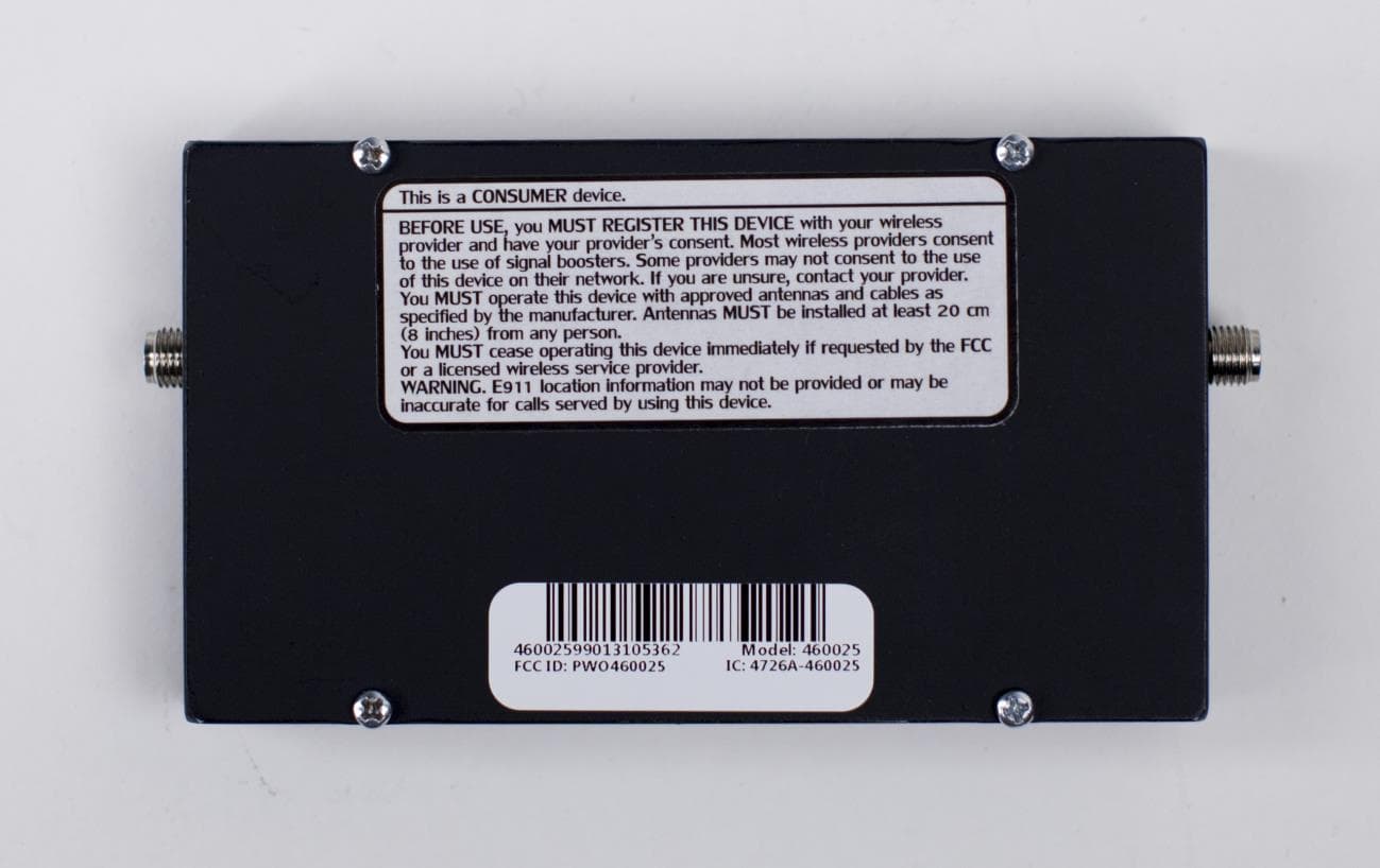
Click to zoom
Application Details
- Equipment Class
- B2W - Part 20 Wideband Consumer Booster (CMRS)
- Date of Grant
- May 11, 2015
- Application Purpose
- Original Equipment
- Date of Application
- May 06, 2015
- Equipment Note
- Quint Band Signal Booster
- Frequency Range
- 1930.00000000 - 1995.00000000
- Company
- Wilson Electronics, LLC
- Country
- United States
Documents & Files
Document Text
Text extracted from the exhibit documents filed with the FCC. Open a document above to read the original.
Users Manual
Signal 4G ® SIGNAL Need help?www.WilsonElectronics.com Tech Support 866-294-1660 Mon.- Fri. Hours: 7 am to 6 pm MST 2 Need help?www.WilsonElectronics.com Tech Support 866-294-1660 Mon.- Fri. Hours: 7 am to 6 pm MST 3 Need help?www.WilsonElectronics.com Tech Support 866-294-1660 Mon.- Fri. Hours: 7 am to 6 pm MST IT IS VERY IMPORTANT TO POWER YOUR SIGNAL BOOSTER USING A SURGE PROTECTED AC POWER STRIP WITH AT LEAST A 1000 JOULE RATING. FAILURE TO DO THIS WILL VOID YOUR WARRANTY IN THE EVENT OF A POWER SURGE OR LIGHTNING STRIKE. !! THE SIGNAL BOOSTER UNIT IS DESIGNED FOR USE IN AN INDOOR, TEMPERATURE- CONTROLLED ENVIRONMENT (LESS THAN 150 DEGREES FAHRENHEIT). IT IS NOT INTENDED FOR USE IN ATTICS OR SIMILAR LOCATIONS SUBJECT TO TEMPERATURES IN EXCESS OF 150°F. Contents Package Contents .....................................................3 Optional Accessories ..................................................3 Before Getting Started .................................................3 Quick Installation. . . . . . . . . . . . . . . . . . . . . . . . . . . . . . . . . . . . . . . . . . . . . . . . . . . . . .3 Installation Diagram ...................................................5 Additional FAQ ........................................................5 Warnings and Recommendations ........................................6 Signal Booster Specifications ...........................................7 Guarantee and Warranty .......................................Back Cover Installation Instructions for the Following Wilson Electronics Signal Booster: Signal 4G SmarTech ® Signal Booster Model #460025 FCC ID: PWO460025 IC: 4726A-460025 The term “IC” before the radio certification number only signifies that Industry Canada technical specifications were met. Before Getting Started Before you install your Signal 4G booster and start enjoying improved cellular reception, please do the following: 1. Read through all the installation steps. This will help you know what to expect from start to finish. 2. Watch the YouTube video demonstrating the Signal 4G installation at: wilsonelectronics.com/ signal4Gvideo 3. Familiarize yourself with all materials in your product package. This will allow you to know which pieces are referenced in the instructions. Quick Installation You can install your Signal 4G booster using the following steps. NOTE: Before completing your installation, create a “soft” installation by putting the components of your Signal 4G booster in place and testing the operation before mounting equipment. Package Contents 5V / 2.5A Power Supply (859948) 3’ RG174 w/ SMA Male to SMA Male (951151) Signal 4G (460025) Optional Accessories and Antennas DC Plug-In 5.5V/2A Power Supply & USB Cable (2D9910 / 359940) 5V/1.5A DC Hardwire Power Supply (859989) Lightning Surge Protector (859902) Appearance of device and accessories may vary. (This product is not marketed by Verizon Wireless or AT&T). 1. Install the Outside Antenna. Select a location on top of the structure that is: • At least 12 inches from any other antennas. • Free of obstructions. • At least 8 inches from any people. The Outside Antenna must be installed vertically on a metallic surface. Mini-Mag Outside Antenna (301126) 4 Need help?www.WilsonElectronics.com Tech Support 866-294-1660 Mon.- Fri. Hours: 7 am to 6 pm MST 5 Need help?www.WilsonElectronics.com Tech Support 866-294-1660 Mon.- Fri. Hours: 7 am to 6 pm MST Power Strip Surge Protector Power Supply Signal 4G Signal Booster Cellular Modem Mini-Mag Antenna Installation Diagram (Figure 1) Additional FAQ: What hours can I contact tech support? Technical Support can be reached from 7:00am to 6:00pm MST, by calling (866-294-1660), or by email, at [email protected]. How does weather affect the performance of my Outside Antenna? Water vapor (e.g. rain, fog, snow or other precipitation) creates an effective filter to cellular signal. In times of heavy precipitation, you may see less performance. What’s the difference between the 800 MHz and the 1900 MHz bands? How do I know which MHz band my cell phone uses? The Signal 4G booster works with all major North American cellular providers. Traditionally, 800/1900MHz are associated with voice and 3G data; while 700MHz and 1700/2100MHz are associated with 4G data. Carrier Frequency Use We recommend visiting www.wirelessadvisor.com (United States) or http://bit.ly/1mQf2Gl (Canada) for information regarding the frequency band used by your cell service provider in a specific geographical location. Fixing Red Light Issues If one or more lights on the Signal Boost are red: 1. Make sure all connections are tight. 2. Increase the distance between the outside antenna and the Drive 4G-S, by moving them horizontally and/or vertically farther apart until the light change to green. Remember to keep the antenna at least 6 inches from any window or sunroof. 3. Follow the same steps for a green/red blinking light until the light goes solid green. 4. If more separation is not possible and the coverage of the booster is too small with a green/red blinking light indicating reduced gain, contact the weBoost Customer Support Team for assistance: 866-294-1660. Lights Off 1. Check connections on the power supply to see that it is firmly plugged into both the Drive 4G-S and the power source. 2. If using a DC power supply in your vehicle, ensure the power supply is properly inserted. Then check the 12 volt power from the car socket and the fuse. Replace the fuse if necessary. 3. If using a power strip in a building, ensure the power strip is plugged in and turned on and that power is coming from the outlet. 2. Select a location to install the Signal Booster that is away from excessive heat, direct sunlight, moisture and that has proper ventilation. Do not place the Signal Booster in an air-tight enclosure. 3. Run the Outside Antenna cable to the Signal Booster and attach it to the connector labeled “Outside Antenna.” 4. An external adapter may be needed to conne…
Text truncated - open the document above for the full version.
Attestation Statements
February 9, 2015 Attestation For Wilson Signal Booster: FCC ID PWO460025 Each Signal Booster certificated under FCC ID PWO460025 is manufactured and individually tested to ensure FCC compliance: (1) Licensee consent is not required for FCC certification equipment authorization purposes, but licensee consent does remain applicable per 20.21 provisions for both provider specific and wideband boosters. (2) NPS and other compliance/safeguard features have been implemented. (3) NPS and other compliance/safeguard features are defaulted to be “On” (in operation). (4) NPS and other compliance/safeguard features cannot be field reconfigured, disabled, or removed. (5) This consumer booster is not user programmable, does not need fine tuning or adjustment, and does not require professiona1l installation. However, in case booster indicator lights show the need, the gain may be adjusted as described in the User Manual. Such adjustments are “fail safe”, i.e., they will not enable the booster to be non-compliant to NPS or other compliance/safeguard requirements. (6) Future software upgrade will not cause non-compliance. Sincerely, Patrick L. Cook Chief Technology Officer
Cover Letter(s)
February 9, 2015 Federal Communications Commission 7435 Oakland Mills Road Columbia, MD 21046 Subject: Data Confidentiality To Whom It May Concern: Wilson Electronics, Inc. respectfully requests confidentiality of certain documentation provided with the submission of our model 460025 Signal Booster under FCC ID: PWO460025 in accordance with sections 0.457 and 0.459 of the Commission’s regulations. We request that the following documents be kept confidential: 1. Schematic Diagram & Parts List 2. Operational Description 3. Block Diagram The above material is confidential and contains proprietary trade secrets and technical data which must be kept from competitors. Public access to these items could result in duplication of our circuitry and/or techniques thereby reducing our competitive advantage and causing us severe damage. Sincerely, Patrick L. Cook Chief Technology Officer
Cover Letter(s)
Subject: Authorized Individuals To Whom It May Concern: Please be advised that I, Erin Elder, as contact of record in the Grantee Code data base, have designated Patrick Cook of Wilson Electronics and Hoosamuddin Bandukwala of H.B. Compliance Solutions as the persons responsible for Wilson Electronics certificate applications submitted by of H.B. Compliance Solutions. Any and all acts carried out by Patrick Cook or Hoosamuddin Bandukwala in matters pertaining to processes required in the FCC approval shall have the same legal authority as acts and communications by the undersigned. They are authorized to respond to any future issues or FCC requests regarding this project. Please send any query, acknowledgement or response to this letter directly to Wilson Electronics. Sincerely, Erin Elder IP & Compliance Engineer
Parts List/Tune Up Info
February 10, 2015 Tuning and Adjustment of Wilson Model 460025 Signal Booster There are no external tuning adjustments. The amplifier is factory set to not exceed maximum gains, power levels, and downlink dependent region (RSSI) set points as provided in the test results. Sincerely, Patrick L. Cook Chief Technology Officer
RF Exposure Info
April 1, 2015 Subject: RF MPE EXPOSURE Re: FCC ID: PWO460025 To Whom It May Concern: The MPE calculations for model 460025 signal booster were done for each frequency band: 1700/2100 MHz, 800 MHz, 700 MHz Band 13, 700 MHz Band 12, and 1900 MHz. For each band two calculations were done; these included the worst case scenario for each of the different types of antennas that may be connected to this signal booster: outside antennas. The order of the attached calculations is as follows: 1700/2100 MHz band: 1. Outside Antenna: 314453‐40075 800 MHz band: 2. Outside Antenna: 311129 ‐400100 700 MHz Band 13: 3. Outside Antenna: 314411‐40075 700 MHz Band 12: 4. Outside Antenna: 314411‐40075 1900 MHz band: 5. Outside Antenna: 314473‐0640 A booster’s uplink power must not exceed 1 watt equivalent isotropic radiated power (EIRP) for each band of operation. Composite downlink power must not exceed 0.05 watt EIRP for each band of operation (20.21(e)(8)(i)(D)). The following formula was used to calculate the equivalent isotropic radiated power: EIRP= Power Out (Watts)*Duty Cycle Percent*Antenna Gain (non‐log)*Coax loss (non‐log) The power density (mW/cm 2 ) is calculated using the following formula: Calculated Power Density=1000*EIRP (Watts)/(4*π*(Distance from Antenna (cm)^2)) Sincerely, Patrick L. Cook Chief Technology Officer Minimum Safe Distance From Antennas Based upon FCC OET Bulletin 65 and other FCC Sources INPUT DATA Frequency MHz1710 Pout Watts0.33884 Duty Cycle Percent100.0% Ant. Gain dBi8.20 Coax Loss dB4.49 Distance From Antenna In cm20.0 Ant. Gain less Coax Loss dBi3.71 Distance From Antenna In Inches7.87 EIRP (Watts)0.7962 FCC Power Density Limit (mw/cm 2 ) 1.00 Calculated Power Density (mw/cm 2 ) 0.1584 REFERENCE DAT A Pout dBm25.30 Antenna Gain (non-log)6.61 Coax loss (non-log)0.36 General FCC Limit (mw/cm 2 ) 1.00 Antenna # 314453-4007 5 RESULTS OF CALCULATIONS 4/1/2015, 3:42 PM1700 MHz .xlsx Minimum Safe Distance From Antennas Based upon FCC OET Bulletin 65 and other FCC Sources INPUT DATA Frequency MHz824 Pout Watts0.26730 Duty Cycle Percent100.0% Ant. Gain dBi9.60 Coax Loss dB4.70 Distance From Antenna In cm20.0 Ant. Gain less Coax Loss dBi4.90 Distance From Antenna In Inches7.87 EIRP (Watts)0.8260 FCC Power Density Limit (mw/cm 2 ) 0.55 Calculated Power Density (mw/cm 2 ) 0.1643 REFERENCE DAT A Pout dBm24.27 Antenna Gain (non-log)9.12 Coax loss (non-log)0.34 General FCC Limit (mw/cm 2 ) f/1500 Antenna # 311129-400100 RESULTS OF CALCULATIONS 4/1/2015, 3:43 PM800 MHz .xlsx Minimum Safe Distance From Antennas Based upon FCC OET Bulletin 65 and other FCC Sources INPUT DATA Frequency MHz698 Pout Watts0.22080 Duty Cycle Percent100.0% Ant. Gain dBi7.30 Coax Loss dB4.50 Distance From Antenna In cm20.0 Ant. Gain less Coax Loss dBi2.80 Distance From Antenna In Inches7.87 EIRP (Watts)0.4207 FCC Power Density Limit (mw/cm 2 ) 0.47 Calculated Power Density (mw/cm 2 ) 0.0837 REFERENCE DAT A Pout dBm23.44 Antenna Gain (non-log)5.37 Coax loss (non-log)0.35 General FCC Limit (mw/cm 2 ) f/1500 Antenna # 314411-4007 5 RESULTS OF CALCULATIONS 4/1/2015, 3:43 PM700 MHz Band 12.xlsx Minimum Safe Distance From Antennas Based upon FCC OET Bulletin 65 and other FCC Sources INPUT DATA Frequency MHz776 Pout Watts0.26915 Duty Cycle Percent100.0% Ant. Gain dBi7.20 Coax Loss dB3.00 Distance From Antenna In cm20.0 Ant. Gain less Coax Loss dBi4.20 Distance From Antenna In Inches7.87 EIRP (Watts)0.7079 FCC Power Density Limit (mw/cm 2 ) 0.52 Calculated Power Density (mw/cm 2 ) 0.1408 REFERENCE DAT A Pout dBm24.30 Antenna Gain (non-log)5.25 Coax loss (non-log)0.50 General FCC Limit (mw/cm 2 ) f/1500 Antenna # 314411-4007 5 RESULTS OF CALCULATIONS 4/1/2015, 3:43 PM700 MHz Band 13.xlsx Minimum Safe Distance From Antennas Based upon FCC OET Bulletin 65 and other FCC Sources INPUT DATA Frequency MHz1850 Pout Watts0.20606 Duty Cycle Percent100.0% Ant. Gain dBi10.00 Coax Loss dB5.26 Distance From Antenna In cm20.0 Ant. Gain less Coax Loss dBi4.74 Distance From Antenna In Inches7.87 EIRP (Watts)0.6138 FCC Power Density Limit (mw/cm 2 ) 1.00 Calculated Power Density (mw/cm 2 ) 0.1221 REFERENCE DAT A Pout dBm23.14 Antenna Gain (non-log)10.00 Coax loss (non-log)0.30 General FCC Limit (mw/cm 2 ) 1.00 Antenna # 314473-0640 RESULTS OF CALCULATIONS 4/1/2015, 3:44 PM1900 MHz .xlsx
Test Report
Certificates and reports shall not be reproduced except in full, without the written permission of H.B Compliance Solutions, LLC. Intentional Radiator Test Report For the Wilson Electronics. Quint Band Bi-Directional Amplifier Model # 460025 Tested under FCC Part 20 For Direct Connect Consumer Signal Booster Prepared for: Wilson Electronics 3301 E. Desert Drive, St. George, UT 8479085224 Prepared By: H.B. Compliance Solutions 5005 S. Ash Avenue, Suite # A-10 Tempe, Arizona 85282 Reviewed By: Hoosamuddin Bandukwala Cert # ATL-0062-E Engineering Statement: The measurements shown in this report were made in accordance with the procedure indicated, I assume full responsibility for the accuracy and completeness of these measurements, and for the qualifications of all persons taking them. HBCS Report # EMC_14052 Rev2 Page 2 of 143 Report Status Sheet Revision # Report Date Reason for Revision Ø January 16, 2015 Initial Issue 1 March 30, 2015 TCB Comments 2 May 06, 2015 Corrected RSSI values in Table 24 HBCS Report # EMC_14052 Rev2 Page 3 of 143 Table of Contents EXECUTIVE SUMMARY ............................................................................................ 4 1. Testing Summary ........................................................................................ 4 EQUIPMENT CONFIGURATION ................................................................................ 5 1. Overview .................................................................................................... 5 2. Test Facility ................................................................................................. 6 3. Description of Test Sample ......................................................................... 6 4. Equipment Configuration ........................................................................... 6 5. Support Equipment .................................................................................... 6 6. Ports and Cabling Information .................................................................... 7 7. Method of Monitoring EUT Operation ........................................................ 7 8. Mode of Operation ..................................................................................... 7 9. Modifications ............................................................................................. 7 10. Disposition of EUT ...................................................................................... 7 Criteria for Intentional Radiators ............................................................................ 8 1. Authorized Frequency Band ....................................................................... 8 2. Maximum Power and Gain ....................................................................... 14 3. Intermodulation ....................................................................................... 16 4. Out-of-band emissions ............................................................................. 22 5. Conducted Spurious Emissions ................................................................. 56 6. Noise Limits .............................................................................................. 80 7. Variable Booster Gain ............................................................................... 85 8. Occupied Bandwidth ................................................................................ 91 9. Oscillation Detection .............................................................................. 122 10. Radiated Spurious Emissions .................................................................. 140 I. Test Equipment ........................................................................................... 143 HBCS Report # EMC_14052 Rev2 Page 4 of 143 EXECUTIVE SUMMARY 1. Testing Summary These tests were conducted on a sample of the equipment for the purpose of demonstrating compliance with FCC Part 20. All tests were conducted using measurement procedure from FCC Signal Booster Measurement KDB 935210 D03 v02r01 July 24, 2014 as appropriate. Test Name Test Method/Standard Result Comments Authorized Frequency Band 20.21(e)(3) Pass Maximum Power & Booster Gain 20.21(e)(8)(i)(B) 20.21(e)(8)(i)(C) 20.21(e)(8)(i)(D) Pass Intermodulation 20.21(e)(8)(i)(F) Pass Out-of-Band Emissions 20.21(e)(8)(i)(E) Pass Conducted Spurious Emissions 2.1051 Pass Noise Limits 20.21(e)(8)(i)(A) 20.21(e)(9)(i)(l) Pass If noise is less than -70dBm/MHz then EUT will not shut off therefore following test are N/A 1) Variable Uplink Noise Power Test 2) Noise Timing Test Uplink Inactivity 20.21(e)(8)(i)(l) 20.21(e)(9)(i)(J) N/A Since noise is less than -70dBm/MHz in normal mode the EUT will not exceed this level after 5 mins when not serving an active device therefore following test are N/A Variable Booster Gain 20.21(e)(8)(i)(C) Pass Occupied Bandwidth 2.1049 Pass Oscillation Detection 20.21(e)(8)(ii)(A) Pass Radiated Spurious Emissions 2.1053 Pass Spectrum Block Filtering 20.21(e)(8)(i)(B) N/A Applies to devices utilizing spectrum block filtering, In this case this is not applicable HBCS Report # EMC_14052 Rev2 Page 5 of 143 EQUIPMENT CONFIGURATION 1. Overview H.B Compliance Solutions was contracted by Wilson Electronics to perform testing on the Bi- Directional Amplifier Model # 460025 under the purchase order number PO460025. This document describes the test setups, test methods, required test equipment, and the test limit criteria used to perform compliance testing of the Wilson Electronics, Bi-Directional Amplifier Model # 460025. The tests were based on FCC Part 20 Rules. The tests described in this document were formal tests as described with the objective of the testing was to evaluate compliance of the Equipment Under Test (EUT) to the requirements of the aforementioned specifications. Wilson Electronics should retain a copy of this document and it should be kept on file for at least five years after the manufac…
Text truncated - open the document above for the full version.
Test Setup Photos
Test Setup Photo # 1 Test Setup Photo # 2 Test Setup Photo # 3 Test Setup Photo # 4
Contact Information
Applicant
Mikel Parry(Compliance Manager)
Technical Contact
Wilson ElectronicsErin Elder
[email protected]4356735021
3301 E Desert Drive St. · George · United States
Test Firm
SMART EC Product Testing ServicesTeresa Kaczmarowski
[email protected]602 437 6898
Technical Specifications
| # | Rule Parts | Frequency Range | Power Output | Emission | Tolerance |
|---|---|---|---|---|---|
| 28 | 24E | 1.93 GHz - 2.00 GHz | 300.00 µW | G7W | Amp |
Other Applications from Wilson Electronics, LLC
PWO086
Mar 09, 2026Single Band Bi-Directional Amplifier
Equipment Class
B2W - Part 20 Wideband Consumer Booster (CMRS)PWO072
Aug 26, 20245G NR Industrial Signal Booster
Equipment Class
B2I - Part 20 Industrial Booster (CMRS)
PWO075
Jan 10, 2024Quint Band Signal Booster
Equipment Class
B2W - Part 20 Wideband Consumer Booster (CMRS)
PWO460065
Nov 04, 2020Dual Band Signal Booster
Equipment Class
B2W - Part 20 Wideband Consumer Booster (CMRS)
PWO460061
Sep 22, 2020Quint Band Signal Booster
Equipment Class
B2W - Part 20 Wideband Consumer Booster (CMRS)