PWO460064WilsonPro 5G-specific cellular amplifier
Wilson Electronics, LLC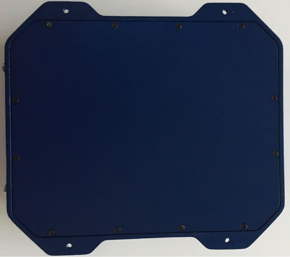
Click to zoom
Application Details
- Equipment Class
- B2I - Part 20 Industrial Booster (CMRS)
- Date of Grant
- May 18, 2020
- Application Purpose
- Original Equipment
- Date of Application
- May 17, 2020
- Equipment Note
- WilsonPro 5G-specific cellular amplifier
- Frequency Range
- 663.00000000 - 698.00000000
- Company
- Wilson Electronics, LLC
- Country
- United States
Documents & Files
Document Text
Text extracted from the exhibit documents filed with the FCC. Open a document above to read the original.
Users Manual
A Wilson Electronics Brand wilsonpro.com866.294.1660 Installation Guide PRO 710i Industrial Class In-Building Cell Signal Amplifier Supporting Band 71 (600MHz) Package Contents 1 About The Pro 710i 2 Key Features 4 Post Install Setup 5 Menu System 7 Safety Guidelines 11 Warranty 13 Index PRO 710i INDUSTRIAL CLASS IN-BUILDING CELL SIGNAL AMPLIFIER 1 Package Contents Pro 710i Kit 460064 INDUSTRIAL CLASS IN-BUILDING CELL SIGNAL AMPLIFIER PRO 710i 2 Up to +25 dBm uplink power and 85 dB gain for maintaining connections with far-away cell towers Up to +25 dBm downlink power for improved indoor cell coverage area Color touch screen, for easy installation and displaying detailed amplifier status eXtended Dynamic Range (XDR) for Continuous Connectivity Industrial Class In-Building Cell Signal Amplifier Supporting Band 71 (600MHz) Pro 710i PRO 710i INDUSTRIAL CLASS IN-BUILDING CELL SIGNAL AMPLIFIER 3 The Pro 710i industrial class, in-building, cell signal amplifier provides significantly enhanced band 71 (600MHz) signal strength, supporting 4G LTE and 5G technology. The Pro 710i can be installed as either a “stand-alone” amplifier providing exclusive band 71 amplification, or it can be combined with a new or existing WilsonPro amplifier system, supporting multiple bands. Because the Pro 710i is an industrial class amplifier, local band 71 carrier approval must be obatined for every installation. The Pro 710i also incorporates Wilson Electronics’ state-of-the-art XDR (eXtended Dynamic Range) technology that prevents signal overload conditions which can, in accordance with regulations, force the amplifier to shut down. When the Pro 710i senses that any incoming cell signal is too strong and threatens to overload the system, XDR automatically reduces amplifier gain to compensate while maintaining signal coverage throughout the building. The Pro 710i incorporates an easy-to-use color LCD touch screen, and both antenna ports are located on the top of the unit for simple installation. Like all WilsonPro cell signal boosters, the Pro 710i amplifier system is universal: it works for all cellular devices, all services and all U.S. and Canada cell phone carriers using band 71 (600MHz). INDUSTRIAL CLASS IN-BUILDING CELL SIGNAL AMPLIFIER PRO 710i 44 Industrial Class Amplification: Up to 100,000 sq. ft. of band 71 (600MHz) coverage with a single amplifier (local carrier approval required for each installation). Extended Dynamic Range (XDR) for continuous connectivity: XDR lets the Pro 710i system work with an incoming signal and never shuts down due to a strong outside signal. Onboard Software for Better Control: The amplifier is automatically controlled with automatic onboard software, ensuring great connectivity throughout large spaces and multi- story buildings. The amplifier will adjust its gain level up or down as required by the conditions of the immediate signal environment. Color LCD Touch Screen: The Pro 710i utilizes a color LCD touch screen, for assessing amplifier performance, making adjustments to the outside antenna, and turning bands on and off. Key Features PRO 710i INDUSTRIAL CLASS IN-BUILDING CELL SIGNAL AMPLIFIER 5 The Pro 710i is designed with advanced internal programming, which allows it to automatically adjust for a variety of conditions, while still amplifying weak signals. Once the antenna cables are connected, turn the unit on by connecting the power supply cord, at the bottom. hand tighten ONLY Inside Antenna Outside Antenna power supply with locking feature slot for installer business card Post Install Setup INDUSTRIAL CLASS IN-BUILDING CELL SIGNAL AMPLIFIER PRO 710i 6 PRO 710i PRO 710i ENTERPRISE 1300 Stand-alone installation, providing cell coverage for band 71 only. Pro710i and Enterprise 1300 (Common Mode) combined. A Wilson Lightning Surge Protector is recommended for all building installations. Make sure the protector is installed outside the building. Connect it to suitable ground and in line, between the Outside Antenna and the Signal Amplifier. Combiner Inside Dome Antenna Inside Dome Antenna Band 71, 600 MHz Cell Tower Band 71, 600 MHz Cell Tower Outside Antennas Outside Antenna Bands 4/5/12/13/25 Cell Tower Installation Diagram Combined Stand Alone PRO 710i INDUSTRIAL CLASS IN-BUILDING CELL SIGNAL AMPLIFIER 7 The Pro 710i takes about 5 seconds to boot up. Once boot up is complete, the home screen will appear, showing the amplification and status of each port and band. A solid green color indicates that a band is operating correctly with maximum allowable gain. A solid yellow color indicates band gain reduction because of an oscillation condition. Reposition antennas (increase separation between indoor and outdoor antennas, and point in opposite directions) and then reboot (turn the unit off & on) the Pro 710i to reactivate the band and maximize performance. When adequate separation is achieved, the yellow color will return to green upon reboot. Note: when the colro is yellow, the band is operational; however, performance is reduced. Start Up Screen Band Menu Color Description Menu System INDUSTRIAL CLASS IN-BUILDING CELL SIGNAL AMPLIFIER PRO 710i 8 A red color indicates a band has been shut down because of a severe oscillation condition or repeated oscillation. Reposition antennas (increase separation between indoor and outdoor antennas, and point in opposite directions) and then reboot (turn the unit off & on) the Pro 710i to reactivate the band and maximize performance. When adequate separation is achieved, the red color will return to green upon reboot. (MENU SYSTEM cont.) PRO 710i INDUSTRIAL CLASS IN-BUILDING CELL SIGNAL AMPLIFIER 9 “Full Gain” is displayed if the there is a weak outside signal requiring the amplifier to operate with maximum allowable gain”. The amplifier is functioning normally; however, a stronger signal might be obtained with some antenna adjustments. “XDR Gain” is displayed , indicating that the amplifier has reduced it’s gain to accommodate a mod…
Text truncated - open the document above for the full version.
Attestation Statements
Attestation For Wilson Signal Booster: FCC ID PWO460064 April 8, 2020 FEDERAL COMMUNICATIONS COMMISSION Authorization and Evaluation Division 7435 Oakland Mills Road Columbia, MD 21046 RE: Attestation for FCC ID: PWO460064 To Whom It May Concern: This letter serves as official statement that the following label will be shown in online and point-of-sale marketing material as well as outside packaging of the device. Sincerely, Mikel Parry Compliance Manager
Cover Letter(s)
April 28, 2020 Federal Communications Commission 7435 Oakland Mills Road Columbia, MD 21046 Subject: Data Confidentiality To Whom It May Concern: Wilson Electronics, Inc. respectfully requests confidentiality of certain documentation provided with the submission of our model 460064 Signal Booster under FCC ID: PWO460064 in accordance with sections 0.457 and 0.459 of the Commission’s regulations. We request that the following documents be kept in long-term confidentiality: 1. Schematic Diagram 2. Parts List – Bill of Materials (BOM) 3. Block Diagram 4. Operational Description 5. Internal Photos • Due to the fact that there are NO user serviceable parts within the enclosure, there is no reason for internal photos to be publicly accessible. There is also no way for an end user to access the internal components of this unit. The above material is confidential and contains proprietary trade secrets and technical data which must be kept from competitors. Public access to these items could result in duplication of our circuitry and/or techniques thereby reducing our competitive advantage and causing us severe damage. The public disclosure of these materials provides unjustified benefits to its competitors in the market. Sincerely, Mikel Parry Compliance Manager
Cover Letter(s)
Agent Authorization Letter April 28, 2020 FEDERAL COMMUNICATIONS COMMISSION Authorization and Evaluation Division 7435 Oakland Mills Road Columbia, MD 21046 Subject: Letter of Agent Authorization To Whom It May Concern: Please be advised that we, Wilson Electronics, hereby authorize Compliance Testing LLC to act on our behalf in all matters relating to application for equipment authorization, FCC ID: PWO 460064, including the signing of all documents relating to these matters. Any and all acts carried out by Wilson Electronics or Compliance Testing LLC in matters pertaining to processes required in the FCC approval shall have the same legal authority as acts and communications by the undersigned. They are authorized to respond to any future issues or FCC requests regarding this project. Please send any query, acknowledgement or response to this letter directly to Wilson Electronics. Sincerely, Mi kel Parry Compliance Manager
ID Label/Location Info
Booster Serial Label Industrial Warning Label
Parts List/Tune Up Info
May 13, 2020 Tuning and Adjustment of Wilson Model 460064 Signal Booster Model 460064 Signal Booster Tuned Frequency (MHz) Target Gain (dB) Maximum Gain (dB) Target Power (dBm) Maximum Power (dBm) Uplink 663-698 85 85 24.2 24.2 Downlink 617-652 85 85.5 24.5 24.5 There are no external tuning adjustments. The amplifier is factory set to not exceed maximum gains, power levels, and downlink dependent region (RSSI) set points as provided in the test results. It is designed with advanced internal programming, which allows it to automatically adjust for a variety of conditions, while still amplifying weak signals. Tune-up Procedure: 1. Once the antennas and antenna cables are connected, turn the unit on by connecting the power supply cord, at the bottom. A Wilson Lightning Surge Protector is recommended for all building installations. Make sure the protector is installed outside the building. Connect it to suitable ground and in line, between the Outside Antenna and the Signal Amplifier. 2. Standard installation Stand-alone installation, providing cell coverage for band 71 only. Sincerely, Mikel Parry Compliance Manager
Parts List/Tune Up Info
Dawn Communication Co., Ltd. 700-960MHz 1710- 2700MHz Add: No.31 Dukou Road, Shatou Avenue, Xinan Street, Sanshui District, Foshan 528100, Guangdong, PRC. Tel: +86-757-8776-8371 Fax: +86-757-8776-8372 Email: [email protected] Website: www.dawn-antenna.com 617-2700MHz 6/8dBi Panel Antenna Model: DB-617-2700-6/8-65 Horizontal Vertical Electrical Specifications Frequency Range(MHz) 617-806 806-960 1710-2700 Gain 6 dBi 8 dBi VSWR ≤2.0 ≤1.5 Polarization Vertical Front to Back Ratio ≥15 dB Horizontal Beam width 100° 90° 65° Vertical Beam width 95° 75° 55° Input Impedance 50 Ω Max. Input Power 50 W Lightning Protection DC Ground Mechanical Specifications Connector N-Female Dimensions 210x180x43 mm Weight 0.6 kg Reflector Material Aluminum Radome Material ABS Operating Temperature -40°C to +65 °C Mounting Pole Ø38-Ø52 mm Dawn Communication Co., Ltd. 700-960MHz 1710- 2700MHz Add: No.31 Dukou Road, Shatou Avenue, Xinan Street, Sanshui District, Foshan 528100, Guangdong, PRC. Tel: +86-757-8776-8371 Fax: +86-757-8776-8372 Email: [email protected] Website: www.dawn-antenna.com 617-2700MHz 9dBi Log Periodic Antenna Model: DBDS-617-2700-9 Horizontal Vertical Electrical Specifications Frequency Range(MHz) 617-806 806-960 1710-2700 Gain 6.5 dBi 8 dBi 9 dBi VSWR ≤2.0 ≤1.5 Polarization Vertical Front to Back Ratio ≥15 dB Horizontal Beam width 100° 95° 90° Vertical Beam width 65° 60° 55° Input Impedance 50 Ω Max. Input Power 50 W Lightning Protection DC Ground Mechanical Specifications Connector N-Female Dimensions 294x210x65 mm Weight 0.80 kg Reflector Material Aluminum Radome Material ABS Operating Temperature -40°C to +65 °C Mounting Pole Ø38-Ø52 mm Dawn Communication Co., Ltd. 700-960MHz 1710- 2700MHz Add: No.31 Dukou Road, Shatou Avenue, Xinan Street, Sanshui District, Foshan 528100, Guangdong, PRC. Tel: +86-757-8776-8371 Fax: +86-757-8776-8372 Email: [email protected] Website: www.dawn-antenna.com
RF Exposure Info
RF MPE EXPOSURE May 13, 2020 FCC ID: PWO460064 The MPE calculations for EUT model 460064 (600 MHz Part 20 Industrial 5GNR) signal booster were done for frequency band: • 600 MHz (Band 71) Antennas recommended for the EUT: Port Frequency Range (MHz) Antenna Model Gain (dBi) Gain (unitless) Uplink 663-698 DBDS-617-2700-9 6.5 4.5 Downlink 617-652 DB-617-2700-6/8-65 6 4 EUT Operating Limits Limits for Uncontrolled Exposure 47 CFR 1.1310 Table 1(B) Frequency Range (MHz) Limit (mw/cm^2) 0.3-1.234 100 1.24-30 180/f^2 30-300 0.2 300-1500 f/1500 1500-100,000 1 EUT Operating Limits Evaluation EUT maximum transmit power dBm (mw) Operating Limit (mw/cm^2) Power density evaluation (mw/cm^2) Minimum safe distance (cm) UL (663 MHz) 24.2 (263) 0.442 0.235 20 DL (617 MHz) 24.5 (282) 0.411 0.224 20 The lowest frequency in each band was used to compute the “worst case” limit. EUT Power Density Evaluation Calculated power density - Uplink: Power density is calculated using maximum uplink transmitted power of 263 mw and unitless antenna gain of 4.5 푆푆= 푃푃 푡푡 퐺퐺 4휋휋푟푟 2 = (263)(4.5) 4휋휋20 2 =0.235 (푚푚푚푚 푐푐푚푚 2 ⁄ ) 푆푆=푃푃푃푃푚푚 푃푃푟푟 퐷퐷푃푃퐷퐷퐷퐷퐷퐷퐷퐷퐷퐷 ( 푚푚푚푚 푐푐푚푚 2 ⁄) 푃푃 푡푡 =푇푇푟푟푇푇퐷퐷퐷퐷푚푚퐷퐷퐷퐷퐷퐷푃푃푟푟 푃푃푃푃푚푚 푃푃푟푟 ( 푚푚푚푚 ) 퐺퐺=퐴퐴퐷퐷퐷퐷푃푃퐷퐷퐷퐷푇푇 퐺퐺푇푇퐷퐷퐷퐷 ( 퐷퐷푃푃퐷퐷푛푛 푃푃푛푛 ) ∗퐶퐶푃푃푇푇퐶퐶 퐿퐿푃푃퐷퐷퐷퐷 ( 퐷퐷푃푃퐷퐷푛푛 푃푃푛푛 ) ∗푑푑푑푑퐷퐷퐷퐷 푐푐퐷퐷푐푐푛푛푃푃 ( % ) 푟푟=퐷퐷퐷퐷퐷퐷퐷퐷푇푇퐷퐷푐푐푃푃 퐷퐷푃푃 푐푐푃푃퐷퐷퐷퐷푃푃푟푟 푃푃표표 푟푟푇푇푑푑퐷퐷푇푇퐷퐷퐷퐷푃푃퐷퐷 푃푃표표 푇푇퐷퐷퐷퐷푃푃퐷퐷퐷퐷푇푇 (푐푐푚푚) At the minimum safe distance of 20 cm, the power density of the EUT is 0.235 (푚푚푚푚 푐푐푚푚 2 ⁄ ), which is less than the operational limit of 0.442 (푚푚푚푚 푐푐푚푚 2 ⁄ ). Therefore, no minimum safe distance calculation is required. Calculated power density - Downlink: Power density is calculated using maximum downlink transmitted power of 282 mw and unitless antenna gain of 4 푆푆= 푃푃 푡푡 퐺퐺 4휋휋푟푟 2 = (282)(4) 4휋휋20 2 =0.224 (푚푚푚푚 푐푐푚푚 2 ⁄ ) 푆푆=푃푃푃푃푚푚 푃푃푟푟 퐷퐷푃푃퐷퐷퐷퐷퐷퐷퐷퐷퐷퐷 ( 푚푚푚푚 푐푐푚푚 2 ⁄) 푃푃 푡푡 =푇푇푟푟푇푇퐷퐷퐷퐷푚푚퐷퐷퐷퐷퐷퐷푃푃푟푟 푃푃푃푃푚푚 푃푃푟푟 ( 푚푚푚푚 ) 퐺퐺=퐴퐴퐷퐷퐷퐷푃푃퐷퐷퐷퐷푇푇 퐺퐺푇푇퐷퐷퐷퐷 ( 퐷퐷푃푃퐷퐷푛푛 푃푃푛푛 ) ∗퐶퐶푃푃푇푇퐶퐶 퐿퐿푃푃퐷퐷퐷퐷 ( 퐷퐷푃푃퐷퐷푛푛 푃푃푛푛 ) ∗푑푑푑푑퐷퐷퐷퐷 푐푐퐷퐷푐푐푛푛푃푃 ( % ) 푟푟=퐷퐷퐷퐷퐷퐷퐷퐷 푇푇퐷퐷푐푐푃푃 퐷퐷푃푃 푐푐푃푃퐷퐷퐷퐷푃푃푟푟 푃푃표표 푟푟푇푇푑푑퐷퐷푇푇퐷퐷퐷퐷푃푃퐷퐷 푃푃표표 푇푇퐷퐷퐷퐷푃푃퐷퐷퐷퐷푇푇 (푐푐푚푚) At the minimum safe distance of 20 cm, the power density of the EUT is 0.224 (푚푚푚푚 푐푐푚푚 2 ⁄ ), which is less than the operational limit of 0.411 (푚푚푚푚 푐푐푚푚 2 ⁄ ). Therefore, no minimum safe distance calculation is required. END OF REPORT
Test Report
p1170003_FCC_Part 20_Rev 2.0 Page 1 of 17 Test Report Prepared for: Wilson Electronics, LLC (weBoost) Model: 460064 Description: Single Band Industrial Booster FCC ID: PWO460064 To FCC Part 20 FCC Part 27 Date of Issue: May 5, 2020 On the behalf of the applicant: Wilson Electronics, LLC (weBoost) 3301 E Deseret Drive St. Geor ge, UT 84790 Attention of: Sam Judd, Compliance Engineer Ph: (435)673-5021 E-Mail: [email protected] Prepared By Compliance Testing, LLC 1724 S. Nevada Way Mesa, AZ 85204 (480) 926-3100 phone / (480) 926-3598 fax www.compliancetesting.com Project No: p2030006 Greg Corbin Project Test Engineer This report may not be reproduced, except in full, without written permission from Compliance Testing All results contained herein relate only to the sample tested p1170003_FCC_Part 20_Rev 2.0 Page 2 of 17 Test Report Revision History Revision Date Revised By Reason for Revision 1.0 May 5, 2020 Greg Corbin Original Document 2.0 May 13, 2020 Greg Corbin Added W7D emission designator to table on pa ge 6 p1170003_FCC_Part 20_Rev 2.0 Page 3 of 17 Table of Contents Description Page Standard Test Conditions and Engineering Practices 5 Test Result Summary 7 Mean Output Power and Amplifier gain 7 AGC Threshold 8 Out-Of-Band Rejection 9 Input-Versus-Output Signal Comparison 11 Mean Output and Amplifier Gain 12 Out-Of-Band/Block Emission (Dual Carrier) 13 Out-Of-Band/Block Emission (Single Carrier) 14 Conducted Spurious Emissions 15 Radiated Spurious Emissions 16 Test Equipment Utilized 17 p1170003_FCC_Part 20_Rev 2.0 Page 4 of 17 ILAC / A2LA Compliance Testing, LLC, has been accredited in accordance with the recognized International Standard ISO/IEC 17025:2005. This accreditation demonstrates technical competence for a defined scope and the operation of a laboratory quality management system (refer joint ISO-ILAC-IAF Communiqué dated January 2009) The tests results contained within this test report all fall within our scope of accreditation, unless noted below. Please refer to http://www.compliancetesting.com/labscope.html for current scope of accreditation. Testing Certificate Number: 2152.01 FCC Site Reg. #349717 IC Site Reg. #2044A-2 Non-accredited tests contained in this report: N/A p1170003_FCC_Part 20_Rev 2.0 Page 5 of 17 Test and Measurement Data All tests and measurement data shown were performed in accordance with FCC Rules and Regulations, KDB 935210 D05 Industrial Booster Basic Measurements v01r04, ANSI C63-26:2015 and FCC Part 2, Part 20.21, Part 27 where appropriate. Standard Test Conditions and Engineering Practices Except as noted herein, the following conditions and procedures were observed during the testing. In accordance with ANSI/TIA 603C, and unless otherwise indicated in the specific measurement results, the ambient temperature of the actual EUT was maintained within the range of 10° to 40°C (50° to 104°F) unless the particular equipment requirements specify testing over a different temperature range. Also, unless otherwise indicated, the humidity levels were in the range of 10% to 90% relative humidity. Environmental Conditions Temp (ºC) Humidity (%) Pressure (mbar) 24.7 – 28.4 29.6 – 35.0 962.3 – 968.7 Measurement results, unless otherwise noted, are worst-case measurements. EUT Description Model: 460064 Description: Single Band Industrial Booster Firmware: N/A Software: N/A Serial Number: 430047B0414918280 Highest Clock Frequency: 84 MHz Additional Information: The EUT is a bi-directional industrial signal amplifier for the boosting of cellular phone signals and data communication devices. The signal booster operates in the 600 MHz band using LTE and 5GNR signals. The nominal gain is 90 dB. The antenna type and gain are: Indoor: Panel, 6 dBi Outdoor: Log Periodic, 6.5 dBi, EUT Operation during Tests The EUT is powered by an AC to DC power converter with 120 vac input and 12 vdc output. The EUT was operated under normal operating conditions. The EUT has no external manual gain control adjustments. p1170003_FCC_Part 20_Rev 2.0 Page 6 of 17 The signal booster uses the following frequency bands. The emission designators listed are representative emission designators used by transmitters whose signal is amplified by this booster. Frequency Band (MHz) Uplink 663 - 698 Downlink 617 - 652 Modulation Type LTE, 5GNR Emission Designators 5GNR LTE G7D, W7D G7D, W7D Accessories: Qty Description Manufacturer Model S/N 1 AC to DC power supply EDAC Power Elec. EA1024P2-120 N/A Cables: none Modifications: none p1170003_FCC_Part 20_Rev 2.0 Page 7 of 17 Test Result Summary Specification Test Name Pass, Fail, N/A Comments KDB 935210 D05 AGC Threshold Pass KDB 935210 D05 Out-of-Band Rejection Pass KDB 935210 D05 Input-Versus-Output Signal Comparison Pass 2.1046 KDB 935210 D05 Mean Output Power and Amplifier gain Pass 2.1049 KDB 935210 D05 Out-Of-Band/Block Emissions Conducted Pass 2.1051 27.53(g) KDB 935210 D05 Spurious Emissions Conducted Pass KDB 935210 D05 Frequency Stability N/A Does not have Frequency translation 2.1053 KDB 935210 D05 Spurious Emissions Radiated Pass p1170003_FCC_Part 20_Rev 2.0 Page 8 of 17 AGC Threshold Engineer: Greg Corbin Test Date: 4/30-2020 Test Procedure A signal generator was connected to the input of the EUT. A spectrum analyzer was connected to the EUT in order to monitor the output power levels. The Signal Generator was configured to produce the necessary broadband and narrow band signals. The input power level was increase in 1 dB increments until the power no longer increased. The input levels were recorded in the table below. Spectrum Analyzer settings Power Channel integration RBW = 1-5% of EBW Video BW = 3x RBW Test Setup Downlink Tuned Frequency (MHz) AGC Threshold (dBm) AWGN GSM 634.5 -59.0 -61.6 Uplink Tuned Frequency (MHz) AGC Threshold (dBm) AWGN GSM 680.5 -59.9 -62.4 Signal Generator EUT Power Attenuator Spectrum Analyzer p1170003_FCC_Part 20_Rev 2.0 Page 9 of 17 Out-Of-Band Rejection Engineer: Greg Corbin Test Date: 4/30/2020 T…
Text truncated - open the document above for the full version.
Test Report
P2030006_FCC_Annex A _ Rev 1.0 Page 1 of 9 Annex A Input vs Output Signal Comparison P2030006_FCC_Annex A _ Rev 1.0 Page 2 of 9 OCC BW_DL_634.5 MHz_AWGN_Input OCC BW_DL_634.5 MHz_AWGN_Input_Pin + 3 dB P2030006_FCC_Annex A _ Rev 1.0 Page 3 of 9 OCC BW_DL_634.5 MHz_AWGN_Output OCC BW_DL_634.5 MHz_AWGN_Output_Pin + 3 dB P2030006_FCC_Annex A _ Rev 1.0 Page 4 of 9 OCC BW_DL_634.5 MHz_GSM_Input OCC BW_DL_634.5 MHz_GSM_Input_Pin + 3 dB P2030006_FCC_Annex A _ Rev 1.0 Page 5 of 9 OCC BW_DL_634.5 MHz_GSM_Output OCC BW_DL_634.5 MHz_GSM_Output_Pin + 3 dB P2030006_FCC_Annex A _ Rev 1.0 Page 6 of 9 OCC BW_UL_680.5 MHz_AWGN_Input OCC BW_UL_680.5 MHz_AWGN_Input_Pin + 3 dB P2030006_FCC_Annex A _ Rev 1.0 Page 7 of 9 OCC BW_UL_680.5 MHz_AWGN_Output OCC BW_UL_680.5 MHz_AWGN_Output_Pin + 3 dB P2030006_FCC_Annex A _ Rev 1.0 Page 8 of 9 OCC BW_UL_680.5 MHz_GSM_Input OCC BW_UL_680.5 MHz_GSM_Input_Pin + 3 dB P2030006_FCC_Annex A _ Rev 1.0 Page 9 of 9 OCC BW_UL_680.5 MHz_GSM_Output OCC BW_UL_680.5 MHz_GSM_Output_Pin + 3 dB
Test Report
P2030006_FCC_Annex B _ Rev 1.0 Page 1 of 17 Annex B Out of Band Emissions (OOBE) P2030006_FCC_Annex B _ Rev 1.0 Page 2 of 17 OOBE_DL_617 - 652 MHz_ 1 AWGN signal_lower band edge OOBE_DL_617 - 652 MHz_ 1 AWGN signal_lower band edge_Pin + 3 dB P2030006_FCC_Annex B _ Rev 1.0 Page 3 of 17 OOBE_DL_617 - 652 MHz_ 1 AWGN signal_upper band edge_Pin + 3 dB OOBE_DL_617 - 652 MHz_ 1 GSM signal_lower band edge P2030006_FCC_Annex B _ Rev 1.0 Page 4 of 17 OOBE_DL_617 - 652 MHz_ 1 GSM signal_lower band edge_Pin + 3 dB OOBE_DL_617 - 652 MHz_ 1 GSM signal_upper band edge P2030006_FCC_Annex B _ Rev 1.0 Page 5 of 17 OOBE_DL_617 - 652 MHz_ 1 GSM signal_upper band edge_Pin + 3 dB OOBE_DL_617 - 652 MHz_ 2 AWGN signals_lower band edge P2030006_FCC_Annex B _ Rev 1.0 Page 6 of 17 OOBE_DL_617 - 652 MHz_ 2 AWGN signals_lower band edge_Pin + 3 dB OOBE_DL_617 - 652 MHz_ 2 AWGN signals_upper band edge P2030006_FCC_Annex B _ Rev 1.0 Page 7 of 17 OOBE_DL_617 - 652 MHz_ 2 AWGN signals_upper band edge_Pin + 3 dB OOBE_DL_617 - 652 MHz_ 2 GSM signals_lower band edge_Pin + 3 dB P2030006_FCC_Annex B _ Rev 1.0 Page 8 of 17 OOBE_DL_617 - 652 MHz_ 2 GSM signals_upper band edge_Pin + 3 dB OOBE_DL_617 - 652 MHz_ 2 GSM signal_lower band edge P2030006_FCC_Annex B _ Rev 1.0 Page 9 of 17 OOBE_DL_617 - 652 MHz_ 2 GSM signal_upper band edge OOBE_DL_617 - 652 MHz_1 AWGN signal_upper band edge P2030006_FCC_Annex B _ Rev 1.0 Page 10 of 17 OOBE_UL_663 - 698 MHz_ 1 AWGN signal_lower band edge OOBE_UL_663 - 698 MHz_ 1 AWGN signal_lower band edge_Pin + 3 dB P2030006_FCC_Annex B _ Rev 1.0 Page 11 of 17 OOBE_UL_663 - 698 MHz_ 1 AWGN signal_upper band edge OOBE_UL_663 - 698 MHz_ 1 AWGN signal_upper band edge_Pin + 3 dB P2030006_FCC_Annex B _ Rev 1.0 Page 12 of 17 OOBE_UL_663 - 698 MHz_ 1 GSM signal_lower band edge OOBE_UL_663 - 698 MHz_ 1 GSM signal_lower band edge_Pin + 3 dB P2030006_FCC_Annex B _ Rev 1.0 Page 13 of 17 OOBE_UL_663 - 698 MHz_ 1 GSM signal_upper band edge OOBE_UL_663 - 698 MHz_ 1 GSM signal_upper band edge_Pin + 3 dB P2030006_FCC_Annex B _ Rev 1.0 Page 14 of 17 OOBE_UL_663 - 698 MHz_ 2 AWGN signals_lower band edge OOBE_UL_663 - 698 MHz_ 2 AWGN signals_lower band edge_Pin + 3 dB P2030006_FCC_Annex B _ Rev 1.0 Page 15 of 17 OOBE_UL_663 - 698 MHz_ 2 AWGN signals_upper band edge OOBE_UL_663 - 698 MHz_ 2 AWGN signals_upper band edge_Pin + 3 dB P2030006_FCC_Annex B _ Rev 1.0 Page 16 of 17 OOBE_UL_663 - 698 MHz_ 2 GSM signal_lower band edge OOBE_UL_663 - 698 MHz_ 2 GSM signal_lower band edge_Pin + 3 dB P2030006_FCC_Annex B _ Rev 1.0 Page 17 of 17 OOBE_UL_663 - 698 MHz_ 2 GSM signal_upper band edge OOBE_UL_663 - 698 MHz_ 2 GSM signal_upper band edge_Pin + 3 dB
Test Report
P2030006_FCC Annex C _ Rev 1.0 Page 1 of 19 Annex C Conducted Spurious Emission P2030006_FCC Annex C _ Rev 1.0 Page 2 of 19 Conducted Emission_DL_AWGN_hi Channel_1 - 7 GHz Conducted Emission_DL_AWGN_hi Channel_30 - 616.9 MHz P2030006_FCC Annex C _ Rev 1.0 Page 3 of 19 Conducted Emission_DL_AWGN_hi Channel_652.1 - 1000 MHz Conducted Emission_DL_AWGN_low Channel_1 - 7 GHz P2030006_FCC Annex C _ Rev 1.0 Page 4 of 19 Conducted Emission_DL_AWGN_low Channel_30 - 616.9 MHz Conducted Emission_DL_AWGN_low Channel_652.1 - 1000 MHz P2030006_FCC Annex C _ Rev 1.0 Page 5 of 19 Conducted Emission_DL_AWGN_mid Channel_1 - 7 GHz Conducted Emission_DL_AWGN_mid Channel_30 - 616.9 MHz P2030006_FCC Annex C _ Rev 1.0 Page 6 of 19 Conducted Emission_DL_AWGN_mid Channel_652.1 - 1000 MHz Conducted Emission_DL_GSM_hi Channel_1 - 7 GHz P2030006_FCC Annex C _ Rev 1.0 Page 7 of 19 Conducted Emission_DL_GSM_hi Channel_30 - 616.9 MHz Conducted Emission_DL_GSM_hi Channel_652.1 - 1000 MHz P2030006_FCC Annex C _ Rev 1.0 Page 8 of 19 Conducted Emission_DL_GSM_low Channel_1 - 7 GHz Conducted Emission_DL_GSM_low Channel_30 - 616.9 MHz P2030006_FCC Annex C _ Rev 1.0 Page 9 of 19 Conducted Emission_DL_GSM_low Channel_652.1 - 1000 MHz Conducted Emission_DL_GSM_mid Channel_1 - 7 GHz P2030006_FCC Annex C _ Rev 1.0 Page 10 of 19 Conducted Emission_DL_GSM_mid Channel_30 - 616.9 MHz Conducted Emission_DL_GSM_mid Channel_652.1 - 1000 MHz P2030006_FCC Annex C _ Rev 1.0 Page 11 of 19 Conducted Emission_UL_AWGN_hi Channel_1 - 7 GHz Conducted Emission_UL_AWGN_hi Channel_30 - 662.9 MHz P2030006_FCC Annex C _ Rev 1.0 Page 12 of 19 Conducted Emission_UL_AWGN_hi Channel_698.1 - 1000 MHz Conducted Emission_UL_AWGN_low Channel_1 - 7 GHz P2030006_FCC Annex C _ Rev 1.0 Page 13 of 19 Conducted Emission_UL_AWGN_low Channel_30 - 662.9 MHz Conducted Emission_UL_AWGN_low Channel_698.1 - 1000 MHz P2030006_FCC Annex C _ Rev 1.0 Page 14 of 19 Conducted Emission_UL_AWGN_mid Channel_1 - 7 GHz Conducted Emission_UL_AWGN_mid Channel_30 - 662.9 MHz P2030006_FCC Annex C _ Rev 1.0 Page 15 of 19 Conducted Emission_UL_AWGN_mid Channel_698.1 - 1000 MHz Conducted Emission_UL_GSM_hi Channel_1 - 7 GHz P2030006_FCC Annex C _ Rev 1.0 Page 16 of 19 Conducted Emission_UL_GSM_hi Channel_30 - 662.9 MHz Conducted Emission_UL_GSM_hi Channel_698.1 - 1000 MHz P2030006_FCC Annex C _ Rev 1.0 Page 17 of 19 Conducted Emission_UL_GSM_low Channel_1 - 7 GHz Conducted Emission_UL_GSM_low Channel_30 - 662.9 MHz P2030006_FCC Annex C _ Rev 1.0 Page 18 of 19 Conducted Emission_UL_GSM_low Channel_698.1 - 1000 MHz Conducted Emission_UL_GSM_mid Channel_1 - 7 GHz P2030006_FCC Annex C _ Rev 1.0 Page 19 of 19 Conducted Emission_UL_GSM_mid Channel_30 - 662.9 MHz Conducted Emission_UL_GSM_mid Channel_698.1 - 1000 MHz
Test Report
P2030006_FCC_Annex D _ Rev 1.0 Page 1 of 7 Annex D Radiated Spurious Emission P2030006_FCC_Annex D _ Rev 1.0 Page 2 of 7 Radiated Spurious_DL_618 MHz_1 - 7 GHz Radiated Spurious_DL_618 MHz_30 - 1000 MHz P2030006_FCC_Annex D _ Rev 1.0 Page 3 of 7 Radiated Spurious_DL_634.5 MHz_1 - 7 GHz Radiated Spurious_DL_634.5 MHz_30 - 1000 MHz P2030006_FCC_Annex D _ Rev 1.0 Page 4 of 7 Radiated Spurious_DL_650 MHz_1 - 7 GHz Radiated Spurious_DL_650 MHz_30 - 1000 MHz P2030006_FCC_Annex D _ Rev 1.0 Page 5 of 7 Radiated Spurious_UL_664 MHz_1 - 7 GHz Radiated Spurious_UL_664 MHz_30 - 1000 MHz P2030006_FCC_Annex D _ Rev 1.0 Page 6 of 7 Radiated Spurious_UL_680.5 MHz_1 - 7 GHz Radiated Spurious_UL_680.5 MHz_30 - 1000 MHz P2030006_FCC_Annex D _ Rev 1.0 Page 7 of 7 Radiated Spurious_UL_696.5 MHz_1 - 7 GHz Radiated Spurious_UL_696.5 MHz_30 - 1000 MHz
Test Setup Photos
Test Setup Photos FCC: PW0460064 IC: 4726A-460064 RF Conducted #1 RF Radiated (30MHz to 1GHz) RF Radiated (testing above 1GHz)
Contact Information
Applicant
Mikel Parry(Compliance Manager)
Technical Contact
Wilson Electronics, LLCSam Judd
[email protected]435-414-9293
3301 E. Deseret Dr. · St. George, Utah · United States
Non-Technical Contact
Wilson Electronics, LLCSam Judd
[email protected]435-414-9293
Test Firm
Compliance Testing, LLCMichael Schafer
Technical Specifications
| # | Rule Parts | Frequency Range | Power Output | Emission | Tolerance |
|---|---|---|---|---|---|
| 4 | 27 | 663 MHz - 698 MHz | 263.00 mW | W7D | Amp |
Other Applications from Wilson Electronics, LLC
PWO086
Mar 09, 2026Single Band Bi-Directional Amplifier
Equipment Class
B2W - Part 20 Wideband Consumer Booster (CMRS)PWO072
Aug 26, 20245G NR Industrial Signal Booster
Equipment Class
B2I - Part 20 Industrial Booster (CMRS)
PWO075
Jan 10, 2024Quint Band Signal Booster
Equipment Class
B2W - Part 20 Wideband Consumer Booster (CMRS)
PWO460065
Nov 04, 2020Dual Band Signal Booster
Equipment Class
B2W - Part 20 Wideband Consumer Booster (CMRS)
PWO460061
Sep 22, 2020Quint Band Signal Booster
Equipment Class
B2W - Part 20 Wideband Consumer Booster (CMRS)