PWO806WB56Bidirectional Amplifier Repeater
Wilson Electronics, LLC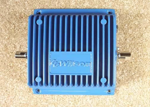
Click to zoom
Application Details
- Equipment Class
- TNB - Licensed Non-Broadcast Station Transmitter
- Date of Grant
- Mar 22, 2004
- Application Purpose
- Original Equipment
- Date of Application
- Mar 22, 2004
- Equipment Note
- Bidirectional Amplifier Repeater
- Frequency Range
- 851.00000000 - 866.00000000
- Company
- Wilson Electronics, LLC
- Country
- United States
Documents & Files


Document Text
Text extracted from the exhibit documents filed with the FCC. Open a document above to read the original.
Users Manual
AMPS IN BUILDING Bi-directional Amplifier #801102 (43dB Model) #801103 (50dB Model) #801104 (60dB Model) FCC ID: PWO824WB56 IC: 4726A-824WB56 iDEN IN BUILDING Bi-directional Amplifier #804001 (43dB Model) #804003 (50dB Model) #804004 (60dB Model) FCC ID: PWO806WB56 IC: 4726A-806WB56 Installation Guide Wilson Electronics, Inc. 3301 E. Deseret Drive, St. George, Utah 84790 For additional technical support go to www.wilsonelectronics.com Phone: 1-866-294-1660 Fax: 1-435-656-2432 IN BUILDING Wireless The term “IC:” before the radio certification number only signifies that Industry of Canada technical specifications were met. 23 1. PURPOSE OF THE AMPS/iDEN AMPLIFIER The AMPS/iDEN Bi-directional Amplifier improves RF coverage for areas in which low signal strength or no signal is a problem. 2. PACKAGE CONTENTS 2.1 AMPS/iDEN Bi-directional Amplifier 2.2 AC-to-DC (110 volt) Power Supply 3. HOW THE AMPS/iDEN AMPLIFIER FUNCTIONS The signal is received by the outside antenna from the cell site. The signal is then AMPLIFIED and transmitted to your phone through the inside antenna. When the phone transmits, the signal is received by the inside antenna and then AMPLIFIED and transmitted to the cell site through the outside antenna. The information provided by Wilson Electronics, Inc. is believed to be complete and accurate. However, no responsibility is assumed by Wilson Electronics, Inc. for any business or per- sonal losses arising from its use, or for any infringements of patents or other rights of third parties that may result from its use. Copyright © 2004 Wilson Electronics, Inc. 23 4. AMPLIFIER INSTALLATION (see illustration on 4-5) 4.1 Installing the Wilson Cellular Outside Antenna 4.1.1 Select a location on the roof using your AMPS/iDEN phone in test mode to find the best signal strength. (See leaflet titled PHONE TEST MODES) 4.1.2 The Outside Antenna should be located in an area with at least a 3’ radius clear of obstructions and other radiating elements. NOTE: Mount the AMPLIFIER away from direct sunlight, excessive heat and/or moisture. The amplifier needs proper ventilation. DO NOT place the amplifier in an air-tight enclosure. WARNING: The outside antenna used with this amplifier must be fixed- mounted on an outdoor permanent structure with a separation of at least 20 feet from all persons during normal operation. 4.2 Installing The Amplifier WARNING: Connecting amplifier directly to cell phone may damage phone. 4.2.1 Mount the AMPLIFIER on a wall or ceiling using #6 screws. 4.2.2 Connect the Outside Antenna to the AMPLIFIER side labeled “OUTSIDE ANTENNA”. 4.2.3 Connect the Inside Antenna to the AMPLIFIER side labeled “INSIDE ANTENNA”. 4.2.4 Verify that both the OUTSIDE and INSIDE antennas are connected be- fore connecting the AC-DC power supply to the power outlet. 4.3 Installing The Wilson Cellular Inside Antenna 4.3.1 The Inside Antenna should be centered in the weak signal area. The INSIDE ANTENNA should be at least 7’ from the ground. WARNING: The inside antenna used with this amplifier must be mounted with a separation distance of at least 8 inches from all persons and must not be co-located or operating in conjunction with any other antenna or amplifier. 4.4 When covering large areas a splitter can be used to allow for more than one inside antenna. Extension cables can also be used if the weak signal area is located far from the location of the outside antenna. NOTE: A minimum of 20’ coax extension is recommended for isolation between antennas. 45 ����� ����������� ��������� ��������������� ������������������� ���� ���� �������� �������� ����� �������������� ������������ ������������ ���������������� ������������������� ������������� ��������������� ������������ 5. AMPLIFIER SPECIFICATIONS FOR AMPS 43dB, 50dB & 60dB MODELS Part #: 801102 (43dB Model) & 801103 (50dB Model) & 801104 (60dB Model) 43dB50dB60dB Frequency824-849MHz Uplink 869-894MHz Downlink Gain (up/down)(43dB/43dB) (50dB/50dB) (60dB/60dB) Flatness (up/down)(+/- 4dB/+/-4dB) (+/- 4dB/+/-6dB)(+/- 4dB/+/-6dB) Max RF (up/down)(+31.7dBm/+10dBm)(+31.7dBm/+10dBm)(+31.7dBm/+10dBm) Noise Figure (down)(3dB nominal) (3dB nominal)(3dB nominal) IsolationUplink/Downlink More than 90dB Power Consumption13.8V, 1.5A 45 AMPLIFIER LAYOUT KEEP A SEPARATION DISTANCE OF AT LEAST 20ft HORIZONTAL AND 5ft VERTI- CAL BETWEEN ANTENNAS If using the Yagi Antenna, make sure the Yagi is pointed AWAY from the inside antenna. ����� ����������� ��������� ��������������� ������������������� ���� ���� �������� �������� ����� �������������� ������������ ������������ ���������������� ������������������� ������������� ��������������� ������������ AMPLIFIER SPECIFICATIONS FOR iDEN 43dB, 50dB & 60dB MODELS Part #: 804001 (43dB Model) & 804003 (50dB Model) & 804004 (60dB Model) 43dB50dB60dB Frequency806-821MHz Uplink 851-866MHz Downlink Gain (up/down)(43dB/43dB) (50dB/50dB) (60dB/60dB) Flatness (up/down)(+/- 4dB/+/-4dB) (+/- 4dB/+/-6dB)(+/- 4dB/+/-6dB) Max RF (up/down)(+31.7dBm/+10dBm)(+31.7dBm/+10dBm)(+31.7dBm/+10dBm) Noise Figure (down)(3dB nominal) (3dB nominal)(3dB nominal) IsolationUplink/Downlink More than 90dB Power Consumption13.8V, 1.5A AMPS/iDEN AMPLIFIER PHYSICAL SPECIFICATIONS Connectors FME-Male 50 Ohms Dimensions 5.5x4.3x1.4 (inch) or 14.0x10.8x3.5 (cm) Weight 1.32 Pounds or 600G 67 6. OPTIONAL ACCESSORIES/ANTENNA OPTIONS 6.1 2-Way RF Splitter - allows for multiple inside antennas. 6.2 Coax Cable Extensions 50Ω (see chart on next page) 6.3 Antenna Options: Inside Antenna Options Outside Antenna Option 301103 - Magnet Mount 301111 - Yagi 301106 - Stealth 301113 - Mini Magnet 6.4 N-Female To FME-Female Adapter - Adapts 9913 Coax to fit the AMPS/ iDEN Bi-directional Amplifier 6.5 Lightning Suppressor WARNING: Lightning protection is recommended for all installations. 6.6 DC Power Cable 7. TECH SUPPORT If you need further assistance with your installation: 1) Call us Toll-Free at 866-294-1660 2) E-mail tech support at [email protected] 3) Go…
Text truncated - open the document above for the full version.
Attestation Statements
DC Voltages UPLINK PA RF3108: Power consumption for all stated modulations 1.75A 5V 8.75watts TX 1.5watts DOWNLINK SGA-3586 MMIC: Power consumption for all stated modulations 35MA 3.3V 80mw RX 10mw MAXIMUM POWER CONSUMPTION FOR AMPLIFIER: 2A 13.8V 27.6watts
Cover Letter(s)
March 2, 2004 Federal Communications Commission 7435 Oakland Mills Road Columbia, MD 21046 Gentlemen: This letter is to comply with section 0.457(d)(2)(i) pertaining to confidential material. Wilson Electronics, Inc. would like the following documents regarding this submission for FCC ID: PWO806WB56 to be kept confidential. 1. CONFIDENTIAL IDEN IN BUILDING REV2 50DB SCHEMATIC.pdf IDEN IN BUILDING REV2 60DB SCHEMATIC.pdf The above material contains trade secrets or technical data, which would customarily be guarded from competitors. We do not want these documents to be accessible to the general public. Sincerely, Patrick Cook, Design Engineer Page 2
External Photos
Front Back Top Bottom Left Right
ID Label/Location Info
• 2.1033(c) (11) Label showing the information to be placed thereon. LABEL Bottom View Page 2
Internal Photos
PCB Top PCB Bottom
Operational Description
To: CKC LABORATORIES Attention: Randal Clark AMPLIFIER DESCRIPTION: MODEL NUMBERS 804003 and 804004 FCC: PWO806WB56 IC: 4726A-806WB56 Frequency 806-821MHz Uplink 851-866MHz Downlink 43dB 50dB 60dB Gain (up/down) (43dB/43dB) (50dB/50dB) (60dB/60dB) Flatness (up/down) (+/- 4dB/+/-4dB) (+/- 4dB/+/-6dB) (+/- 4dB/+/-6dB) Max RF (up/down) (+31.7dBm/+10dBm) (+31.7dBm/+10dBm) (31.7dBm/+10dBm) Noise Figure (down) (3dB nominal) (3dB nominal) (3dB nominal) Isolation Uplink/Downlink More than 90dB Power Consumption 13.8V, 2A Supported Modulations: TDMA Operational Description: The in building amplifier is a bidirectional linear amplifier that receives signals from a cell site and transmits them inside the building at a maximum RF downlink (RX) power of 10dbm (conducted). It also transmits signals from the phone back to the cell site at a maximum uplink (TX) power of +35dbm (conducted). UPLINK PA RF3108: Power consumption for all stated modulations 1.75A 5V 8.75watts TX 1.5watts (25% DUTY CYCLE) DOWNLINK SGA-3586 MMIC: Power consumption for all stated modulations 35MA 3.3V 80mw RX 10mw MAXIMUM POWER CONSUMPTION FOR AMPLIFIER: 2A 13.8V 27.6watts
Parts List/Tune Up Info
Tune-Up Procedure The Tune up procedure is not applicable because the amplifiers are factory set.
Test Report
Page 1 of 38 Report No.: FC04-010 WILSON ELECTRONICS TEST REPORT FOR THE BIDIRECTIONAL AMPLIFIER REPEATER, 804003 FCC PART 90 AND RSS 131 COMPLIANCE DATE OF ISSUE: FEBRUARY 3, 2004 PREPARED FOR: Wilson Electronics 3301 East Deseret Drive St. George, UT 84790 PREPARED BY: Mary Ellen Clayton CKC Laboratories, Inc. 5473A Clouds Rest Mariposa, CA 95338 W.O. No.: 81775Date of test: January 27-29, 2004 Report No.: FC04-010 This report contains a total of 38 pages and may be reproduced in full only. Partial reproduction may only be done with the written consent of CKC Laboratories, Inc. The results in this report apply only to the items tested, as identified herein. Page 2 of 38 Report No.: FC04-010 TABLE OF CONTENTS Administrative Information .............................................................................................3 Summary of Results .........................................................................................................4 Comparison Matrix ..........................................................................................................4 Conditions for Compliance ..............................................................................................4 Approvals .........................................................................................................................4 Equipment Under Test (EUT) Description ......................................................................5 Equipment Under Test .....................................................................................................5 Peripheral Devices ...........................................................................................................5 Measurement Uncertainty ................................................................................................5 Temperature and Humidity During Testing.....................................................................6 FCC 2.1033(c)(3) User’s Manual ....................................................................................6 FCC 2.1033(c)(4) Type of Emissions ..............................................................................6 FCC 2.1033(c)(5) Frequency Range................................................................................6 FCC 2.1033(c)(6) Operating Power.................................................................................6 FCC 2.1033(c)(7) Maximum Power Rating ....................................................................6 FCC 2.1033(c)(8) DC Voltages .......................................................................................6 FCC 2.1033(c)(9) Tune-Up Procedure ............................................................................6 FCC 2.1033(c)(10) Schematics and Circuitry Description..............................................6 FCC 2.1033(c)(11) Label and Placement ........................................................................6 FCC 2.1033(c)(12) Submittal Photos ..............................................................................6 FCC 2.1033(c)(13) Modulation Information ...................................................................6 FCC 2.1033(c)(14)/2.1046/90.205 - RF Power Output ...................................................7 FCC 2.1033(c)(14)/2.1047(b) - Audio Frequency Response...........................................8 FCC 2.1033(c)(14)/2.1047(b) - Modulation Limiting Response.....................................8 FCC 2.1033(c)(14)/2.1049(i)/90.210 - EMISSIONS MASK ..........................................9 FCC 2.1051 - Intermodulation Attenuation .....................................................................13 FCC 2.1033(c)(14)/2.1051/90.210 - Spurious Emissions at Antenna Terminal..............16 FCC 2.1033(c)(14)/2.1053/90.210 - Field Strength of Spurious Radiation ....................26 Output Plot .......................................................................................................................30 Input Plot..........................................................................................................................32 RSS 131 - Downlink Passband Gain ...............................................................................34 RSS 131 - Downlink Passbandwidth 20Db .....................................................................35 RSS 131 - Uplink Passband Gain ....................................................................................36 RSS 131 - Uplink Passbandwidth 20dB ..........................................................................37 Page 3 of 38 Report No.: FC04-010 ADMINISTRATIVE INFORMATION DATE OF TEST: January 27-29, 2004 DATE OF RECEIPT: January 27, 2004 PURPOSE OF TEST: To demonstrate the compliance of the Bidirectional Amplifier Repeater, 804003 with the requirements for FCC Part 90 and RSS 131 devices. TEST METHOD: FCC Part 90, RSS 131 and TIA/EIA 603 FREQUENCY RANGE TESTED: 30 MHz - 10 GHz MANUFACTURER: Wilson Electronics 3301 East Deseret Drive St. George, UT 84790 REPRESENTATIVE: Patrick Cook TEST LOCATION: CKC Laboratories, Inc. 5473A Clouds Rest Mariposa, CA 95338 Page 4 of 38 Report No.: FC04-010 SUMMARY OF RESULTS As received, the Wilson Electronics Bidirectional Amplifier Repeater, 804003 was found to be fully compliant with the following standards and specifications: United States ¾ FCC Part 90 Canada RSS-131 using: ¾ FCC Part 90 COMPARISON MATRIX Canadian Standard Canadian Section FCC Standard FCC Section Test Description RSS 1315.4N/AN/AExternal Controls RSS 1315.547 CFR1.1307RF Exposure RSS 1316.1N/AN/APassband Gain and Bandwidth RSS 1316.247 CFR90.205RF Power Output RSS 1316.3TIA/EIA603Non-Linearity (Intermodulation Attenuation) RSS 1316.447 CFR90.210Spurious Emissions Limitations RSS 1316.5N/AN/AFrequency Stability (Band Translators) CONDITIONS FOR COMPLIANCE No modifications to the EUT were necessary to comply. APPROVALS Steve Behm, Director of Engineering Services QUALITY ASSURANCE:T…
Text truncated - open the document above for the full version.
Test Report
Page 1 of 40 Report No.: FC04-011 WILSON ELECTRONICS TEST REPORT FOR THE BIDIRECTIONAL AMPLIFIER REPEATER, 804004 FCC PART 90 AND RSS 131 COMPLIANCE DATE OF ISSUE: FEBRUARY 4, 2004 PREPARED FOR: Wilson Electronics 3301 East Deseret Drive St. George, UT 84790 PREPARED BY: Mary Ellen Clayton CKC Laboratories, Inc. 5473A Clouds Rest Mariposa, CA 95338 W.O. No.: 81776Date of test: January 15-30, 2004 Report No.: FC04-011 This report contains a total of 40 pages and may be reproduced in full only. Partial reproduction may only be done with the written consent of CKC Laboratories, Inc. The results in this report apply only to the items tested, as identified herein. Page 2 of 40 Report No.: FC04-011 TABLE OF CONTENTS Administrative Information .............................................................................................3 Summary of Results .........................................................................................................4 Comparison Matrix ..........................................................................................................4 Conditions for Compliance ..............................................................................................4 Approvals .........................................................................................................................4 Equipment Under Test (EUT) Description ......................................................................5 Equipment Under Test .....................................................................................................5 Peripheral Devices ...........................................................................................................5 Measurement Uncertainty ................................................................................................5 Temperature and Humidity During Testing.....................................................................6 FCC 2.1033(c)(3) User’s Manual ....................................................................................6 FCC 2.1033(c)(4) Type of Emissions ..............................................................................6 FCC 2.1033(c)(5) Frequency Range................................................................................6 FCC 2.1033(c)(6) Operating Power.................................................................................6 FCC 2.1033(c)(7) Maximum Power Rating ....................................................................6 FCC 2.1033(c)(8) DC Voltages .......................................................................................6 FCC 2.1033(c)(9) Tune-Up Procedure ............................................................................6 FCC 2.1033(c)(10) Schematics and Circuitry Description..............................................6 FCC 2.1033(c)(11) Label and Placement ........................................................................6 FCC 2.1033(c)(12) Submittal Photos ..............................................................................6 FCC 2.1033(c)(13) Modulation Information ...................................................................6 FCC 2.1033(c)(14)/2.1046/90.205 - RF Power Output ...................................................7 FCC 2.1033(c)(14)/2.1047(b) - Audio Frequency Response...........................................8 FCC 2.1033(c)(14)/2.1047(b) - Modulation Limiting Response.....................................8 FCC 2.1033(c)(14)/2.1049(i)/90.210 - Emissions Mask .................................................9 FCC 2.1051 - Intermodulation Attenuation .....................................................................14 FCC 2.1033(c)(14)/2.1051/90.210 - Spurious Emissions at Antenna Terminal..............19 FCC 2.1033(c)(14)/2.1053/90.210 - Field Strength of Spurious Radiation ....................27 Output Plot .......................................................................................................................31 Input Plot..........................................................................................................................33 RSS 131 – 20dB Bandwidth Plot.....................................................................................35 RSS 131 - Downlink Passband Gain ...............................................................................36 RSS 131 - Downlink 20dB Passbandwidth .....................................................................37 RSS 131 - Uplink Passband Gain ....................................................................................38 RSS 131 - Uplink 20dB Passbandwidth ..........................................................................39 Page 3 of 40 Report No.: FC04-011 ADMINISTRATIVE INFORMATION DATE OF TEST: January 15-30, 2004 DATE OF RECEIPT: January 15, 2004 PURPOSE OF TEST: To demonstrate the compliance of the Bidirectional Amplifier Repeater, 804004 with the requirements for FCC Part 90 and RSS 131 devices. TEST METHOD: FCC Part 90 and RSS 131 FREQUENCY RANGE TESTED: 30 MHz - 10 GHz MANUFACTURER: Wilson Electronics 3301 East Deseret Drive St. George, UT 84790 REPRESENTATIVE: Patrick Cook TEST LOCATION: CKC Laboratories, Inc. 5473A Clouds Rest Mariposa, CA 95338 Page 4 of 40 Report No.: FC04-011 SUMMARY OF RESULTS As received, the Wilson Electronics Bidirectional Amplifier Repeater, 804004 was found to be fully compliant with the following standards and specifications: United States ¾ FCC Part 90 Canada RSS-131 using: ¾ FCC Part 90 COMPARISON MATRIX Canadian Standard Canadian Section FCC Standard FCC Section Test Description RSS 1315.4N/AN/AExternal Controls RSS 1315.547 CFR1.1307RF Exposure RSS 1316.1N/AN/APassband Gain and Bandwidth RSS 1316.247 CFR90.205RF Power Output RSS 1316.3TIA/EIA603Non-Linearity (Intermodulation Attenuation) RSS 1316.447 CFR90.210Spurious Emissions Limitations RSS 1316.5N/AN/AFrequency Stability (Band Translators) CONDITIONS FOR COMPLIANCE No modifications …
Text truncated - open the document above for the full version.
Test Setup Photos
DIRECT CONNECT TEST SETUP PHOTOGRAPH SHOWING RADIATED EMISSIONS Radiated Emissions - Front View PHOTOGRAPH SHOWING RADIATED EMISSIONS Radiated Emissions - Back View DIRECT CONNECT TEST SETUP PHOTOGRAPH SHOWING RADIATED EMISSIONS Radiated Emissions - Front View PHOTOGRAPH SHOWING RADIATED EMISSIONS Radiated Emissions - Back View
Contact Information
Applicant
Mikel Parry(Compliance Manager)
Technical Contact
CKC Laboratories, Inc.Mary Ellen Clayton
[email protected]209-966-5240
5473A Clouds Rest · Mariposa, California · United States
Non-Technical Contact
CKC Laboratories, Inc.Mary Ellen Clayton
[email protected]209-966-5240
Test Firm
CKC Laboratories, Inc.Steve Behm
Technical Specifications
| # | Rule Parts | Frequency Range | Power Output | Emission | Tolerance |
|---|---|---|---|---|---|
| 2 | 9 | 851 MHz - 866 MHz | 12.00 mW | GXW | Amp |
Other Applications from Wilson Electronics, LLC
PWO086
Mar 09, 2026Single Band Bi-Directional Amplifier
Equipment Class
B2W - Part 20 Wideband Consumer Booster (CMRS)PWO072
Aug 26, 20245G NR Industrial Signal Booster
Equipment Class
B2I - Part 20 Industrial Booster (CMRS)
PWO075
Jan 10, 2024Quint Band Signal Booster
Equipment Class
B2W - Part 20 Wideband Consumer Booster (CMRS)
PWO460065
Nov 04, 2020Dual Band Signal Booster
Equipment Class
B2W - Part 20 Wideband Consumer Booster (CMRS)
PWO460061
Sep 22, 2020Quint Band Signal Booster
Equipment Class
B2W - Part 20 Wideband Consumer Booster (CMRS)