PWO806WViDen in Car Amplifier
Wilson Electronics, LLC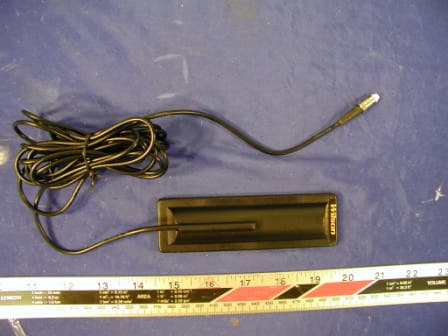
Click to zoom
Application Details
- Equipment Class
- AMP - Amplifier
- Date of Grant
- Nov 10, 2003
- Application Purpose
- Original Equipment
- Date of Application
- Oct 15, 2003
- Equipment Note
- iDen in Car Amplifier
- Frequency Range
- 851.11250000 - 865.88750000
- Company
- Wilson Electronics, LLC
- Country
- United States
Documents & Files
Document Text
Text extracted from the exhibit documents filed with the FCC. Open a document above to read the original.
Users Manual
Rev 1 MODEL: BD800NM PART#: 804002 IDEN MOBIL Bi-Directional Amplifier for In Vehicle Installation Guide The information provided by Wilson Electronics, Inc. is believed to be complete and accurate. However, no responsibility is assumed by Wilson Electronics, Inc. for any business or personal losses arising from its use, or for any infringements of patents or other rights of third parties that may result from its use. FCC ID: PWO806WV Copyright © 2002 Wilson Electronics, Inc. IC: 4726A-806WV 3301 E. Deseret Drive St. George, Utah 84790 wilsonelectronics.com [email protected] Phone 1-866-294-1660 Fax 1-435-656-2432 Rev 1 PAGE 2 TABLE OF CONTENTS 1. PACKAGE CONTENTS...............................................page 3 2. ANTENNA OPTIONS... ................................................page 3 3. PURPOSE OF THE IDEN............... ................................page 4 4. HOW THE IDEN FUNCTIONS............ ............................page 4 5. FEATURES...............................................................page 4 6. AMPLIFIER SPECIFICATIONS.................................... page 4 7. AMPLIFIER INSTALLATION................................. page 5 & 6 8. TECH SUPPORT........................................................page 6 9. NOTES & WARNINGS.................................................page 6 Rev 1 PAGE 3 Rev 1 PAGE 4 1. PURPOSE OF THE IDEN The IDEN Bi-Directional Amplifier greatly improves RF coverage for areas in which low signal strength or no signal is a problem when using your portable iDEN phone inside the car. 2. HOW THE IDEN FUNCTIONS The signal is received by the outside antenna from the cell site. It is then AMPLIFIED/REPEATED and transmitted to your iDEN phone through the inside antenna. When the phone transmits it is received by the inside antenna. It is then AMPLIFIED/REPEATED and transmitted to the cell site through the outside antenna. 3. FEATURES Wireless Operation - No Physical Connection to Cellphone The IDEN Amplifier greatly improves signal strength inside a vehicle without a physical connection to your phone. It also allows multiple phones to be used simultaneously. Advanced Electronics Receive & Transmit Better Than Your Cellphone The Wilson Cellular Amplifier has a better receiver than what's in your cellphone. Its advanced electronics are very sensitive and able to receive small signals that would go undetected by most cellphones. It also has a better transmitter with double the power of your cellphone. This allows your voice to be heard by distant cell sites, increasing coverage up to 50 miles or more. 4. AMPLIFIER SPECIFICATIONS Frequency.........................806-821 MHz Uplink 851-866 MHz Downlink Gain...............................37dB Uplink 37dB Downlink Flatness...........................+/- 3dB Uplink +/- 3dB Downlink Max RF Output Power... .......+31dBm Uplink +15dBm Downlink Noise Figure.................. ....5dB Uplink 5dB Downlink Uplink Downlink Isolation.. ....More than 90dB Power Consumption.............12V, 1.5A Connecter.................. ........FME-Male 50 Ohms Dimensions.......................5.5 x 4.3 x 1.4 (inches) OR 14.0 x 10.8 x 3.5 (cm) Weight......................... ....1.32 pounds or 600 grams Model #...........................IDEN Part #......................... ...... 804002 Rev 1 PAGE 5 5. AMPLIFIER INSTALLATION (REFER TO ILLUSTRATION) ILLUSTRATION 5.1 Mounting the Amplifier 5.1.1 Mount the AMPLIFIER under the dash or car seat. NOTE: The amplifier should be mounted to the selected location using mounting screws. (Mounting screws not included.) 5.2 Installing the Outside Antenna (Sold Separately) 5.2.1 Select an outside mounting location. For best performance try to keep the antenna centered on the car’s / truck’s roof. 5.2.2 The outside antenna should be located in an area with at least a 12” radius clear of obstructions, and other radiating elements. NOTE: When using a magnet mount, NMO or trucker antenna, keep the separation distance between the inside and outside antennas at least 4ft. When using a glass mount antenna , keep the separation distance between the inside and outside antennas at least 5ft. WARNING: The outside antenna used with this amplifier must be mounted with a separation distance of at least 10 inches(25cm) from all persons and must not be co-located or operating in conjunction with any other antenna or amplifier. 5.2.3 Connect the Outside Antenna to the AMPLIFIER/ side labeled “OUTSIDE ANTENNA”. Rev 1 PAGE 6 5.3 Installing the Inside Antenna (Included) 5.3.1 Connect the Inside Antenna to the side labeled “INSIDE ANTENNA” on the AMPLIFIER. 5.3.2 The Inside Antenna should be centered in the vehicle. It can be placed in the seat back between the seat cushion and fabric or in the vehicle headliner. WARNING: The inside antenna used with this amplifier must be mounted with a separation distance of at least 8 inches(20cm) from all persons and must not be co-located or operating in conjunction with any other antenna or amplifier. 5.4 Connect the 12V Power Supply 5.4.1 Connect the large end of the 12V Power Supply into your cigarette lighter and the other end into the input on your amplifier labeled “DC 12V IN”. 7. TECH SUPPORT If you need further assistance with your installation please call us Toll-Free at 866- 294-1660 or send an E-mail to [email protected] Our Hours of Operation are: 8:00 AM – 4:30 PM (Mountain Time) 8. NOTES & WARNINGS NOTE: When using a magnet mount, NMO or trucker antenna , keep the separation distance between the inside and outside antennas at least 4ft. When using a glass mount antenna , keep the separation distance between the inside and outside antennas at least 5ft. WARNING: The outside antenna used with this amplifier must be mounted with a separation distance of at least 8 inches(20cm) from all persons and must not be co-located or operating in conjunction with any other antenna or amplifier. WARNING: The inside antenna used with this amplifier must be mou…
Text truncated - open the document above for the full version.
Cover Letter(s)
August, 12 2003 Federal Communications Commission 7435 Oakland Mills Road Columbia, MD 21046 Gentlemen: This letter is to comply with section 0.457(d)(2)(i) pertaining to confidential material. Wilson Electronics, Inc. would like the following documents regarding this submission for FCC ID: PWO806WV to be kept confidential. 1. CONFIDENTIAL NEXTEL MOBIL SCHEMATIC.PDF The above material contains trade secrets or technical data, which would customarily be guarded from competitors. We do not want these documents to be accessible to the general public. Sincerely, Patrick Cook, Design Engineer Page 2
Cover Letter(s)
August, 12 2003 Federal Communications Commission 7435 Oakland Mills Road Columbia, MD 21046 We the undersigned, herby certify that, in the case of individual applicant, he or she is not subject to a denial of federal benefits pursuant to section 5301 of the Anti-Drug Abuse Act of 1988, 21 USC 853a or in the case of non-individual applicant (e.g. corporation, partnership or other unincorporated association), no party to the applicant is subject to a denial of federal benefit pursuant to that action. Sincerely, Patrick Cook, Design Engineer
External Photos
Wilson Electronics, Inc. FCC ID: PWO806WV EXHIBIT C - EUT PHOTOGRAPHS EUT – Top View EUT – Bottom View Wilson Electronics, Inc. FCC ID: PWO806WV Trucker Antenna Stealth Antenna Wilson Electronics, Inc. FCC ID: PWO806WV Mini Magnet Antenna Mini Gas Antenna Wilson Electronics, Inc. FCC ID: PWO806WV Magnet Mount Antenna Glass Mount Antenna Wilson Electronics, Inc. FCC ID: PWO806WV NMO Mount Antenna
ID Label/Location Info
EXHIBIT A - FCC PRODUCT LABELING AND WARNING STATEMENT FCC ID Label Specifications: Text is black or white in color and is left justified. Labels are silk-screened and shall be “permanently affixed” at a conspicuous location on the EUT. Proposed Label Location on EUT Bottom View of the EUT / Proposed Label Location FCC Warning Statement A FCC Warning Statement is provided in the product manual. FCC ID: Q4EUSHR-800 FCC ID: PWO806WV
Internal Photos
Wilson Electronics, Inc. FCC ID: PWO806WV EUT – Board Front View EUT – Board Front View Wilson Electronics, Inc. FCC ID: PWO806WV EUT – Circuit Board in AMP EUT – Board and Housing View
Parts List/Tune Up Info
AMP800IM QTYVALUEPART LOCATION CAPACITORS 30100pF C3, C5, C7, C10, C16, C19, C21, C22, C26, C27,C27S, C28S, C29, C29S, C30S, C32S, C33S, C34, C34S, C35, C35S, C36S, C39, C41, C42, C43, C45, C46, C49 12.2uF 16V C12 5.1uFC14, C17, C20, C28, C33 11.5pFNOT PLACED 2 27.0pFC15, C18 668pFC1, C2, C8, C9, C23, C24 322pFC30, C38, C40 131nF (1000pF) C4, C6, C11, C13, C25, C31, C31S, C36, C37, C44, C47, C48, C50 1NOT PLACEDC32 RESISTORS 418 R6, R9, R12, R19 233 R17, R26 651 R3S, R29, R30, R31, R36, R39 151 R23 156 R10 175 R2 2200 R24, R25 3100 R18, R1, R3 1100 R37 3120 R21, R22, R38S 1150 R38 9300 R4, R5, R7, R8, R11, R13, R14, R20, R27 12200 R15 710K R28, R28S, R30S, R31S, R32S, R39S,R43S 11.2K R16 15.1K 1%R41S 4100K 1%R29S, R33S, R34S, R42S 1NOT PLACEDNOT PLACED 1 INDUCTORS 15.4nHL4 422nHL1, L2, L3, L5 147nhL11S UPLINK FILTERS 1 SAW813 FL4 DOWNLINK FILTERS 3SAW855FL1, FL2, FL3 VOLTAGE REGULATOR 1L7805 5V REG5V REG AMPLIFIERS 3LOW NOISE MMIC MMIC_1, MMIC_2, MMIC_3 13W AMP RF3108 1ATF-551M4LNA COMPARATOR 1DUAL COMPDC1 DIODE 13AMPNOT PLACED DUPLEXERS 2SPECTRUMDUP855 DUP1, DUP2
RF Exposure Info
11 - RF EXPOSURE According to §15.247(b)(4) and §1.1307(b)(1), systems operating under the provisions of this section shall be operated in a manner that ensures that the public is not exposed to radio frequency energy level in excess of the Commission’s guidelines. According to §1.1310 and §2.1093 RF exposure is calculated. Limits for General Population/Uncontrolled Exposure Frequency Range (MHz) Electric Field Strength (V/m) Magnetic Field Strength (A/m) Power Density (mW/cm 2 ) Averaging Time (minute) Limits for General Population/Uncontrolled Exposure 0.3-1.346141.63*(100)30 1.34-30824/f2.19/f*(180/f 2 )30 30-30027.50.0730.230 300-1500//f/150030 1500-100,000//1.030 f = frequency in MHz * = Plane-wave equivalent power density MPE Prediction Predication of MPE limit at a given distance Equation from page 18 of OET Bulletin 65, Edition 97-01 S = PG/4πR² Where: S = power density P = power input to antenna G = power gain of the antenna in the direction of interest relative to an isotropic radiator R = distance to the center of radiation of the antenna Maximum peak output power at antenna input terminal: 30.5 (dBm) Maximum peak output power at antenna input terminal: 1122 (mW) Trucker Antenna: Prediction distance: 150 (cm) Predication frequency: 800 (MHz) Antenna Gain (typical): 5.12 (dBi) antenna gain: 3.25 (numeric) Power density at predication frequency at 150 cm: 0.013 (mW/cm 2 ) MPE limit for uncontrolled exposure at prediction frequency: 0.53 (mW/cm 2 ) Mini Magnet: Prediction distance: 20 (cm) Predication frequency: 800 (MHz) Antenna Gain (typical): 2.12 (dBi) antenna gain: 1.63 (numeric) Power density at predication frequency at 150 cm: 0.47 (mW/cm 2 ) MPE limit for uncontrolled exposure at prediction frequency: 0.53 (mW/cm 2 ) Wilson Electronics, Inc. FCC ID: PWO806WV Test Result The EUT is a mobile device. The trucker antenna’s power density level at 150 cm (5 ft) is 0.013 mW/cm², which is below the uncontrolled exposure limit of 0.53mW/cm² at 800 MHz. The mini magnet and stealth antenna’s power density level at 20 cm (8 inch) is 0.47 mW/cm², which is also below the uncontrolled exposure limit of 0.53mW/cm² at 800 MHz.
Test Report
Note: This test report is specially limited to the above client company and the product model only. It may not be duplicated without prior written consent of Bay Area Compliance Laboratory Corporation. This report must not be used by the client to claim product endorsement by NVLAP or any agency of the U.S. Government. FCC PART 90 EMI MEASUREMENT AND TEST REPORT For Wilson Electronics, Inc. 3301 EAST DESERET DRIVE SAINT GEORGE, UTAH, 84790 FCC ID: PWO806WV 2003-09-17 This Report Concerns: Original Report Equipment Type: IDEN Mobile Bi-Directional Amplifier Test Engineer:Benjamin Jing / Report No.:R0308081 Test Date:2003-09-04 Reviewed By:Hans Mellberg / Prepared By:Bay Area Compliance Laboratory Corporation 230 Commercial Street Sunnyvale, CA 94085 Tel: (408) 732-9162 Fax: (408) 732 9164 Wilson Electronics, Inc. FCC ID: PWO806WV Report # R0308081RptPage 2 of 30FCC Part 90 Type Approval report TABLE OF CONTENTS 1 - GENERAL INFORMATION.................................................................................................................................................3 1.1 PRODUCT DESCRIPTION FOR EQUIPMENT UNDER TEST (EUT).........................................................................................3 1.2 OBJECTIVE................................................................................................................................................................................3 1.3 RELATED SUBMITTAL(S)/GRANT(S)......................................................................................................................................3 1.4 TEST METHODOLOGY.............................................................................................................................................................3 1.5 TEST FACILITY.........................................................................................................................................................................4 1.6 TEST EQUIPMENT LIST AND DETAILS...................................................................................................................................5 1.7 EXTERNAL I/O CABLING LIST AND DETAILS......................................................................................................................5 2 - SYSTEM TEST CONFIGURATION..................................................................................................................................6 2.1 JUSTIFICATION.........................................................................................................................................................................6 2.2 SCHEMATICS/BLOCK DIAGRAM............................................................................................................................................6 2.3 TEST SETUP BLOCK DIAGRAM..............................................................................................................................................6 2.4 EQUIPMENT MODIFICATIONS.................................................................................................................................................6 3 - SUMMARY OF TEST RESULTS........................................................................................................................................7 4 – CONDUTED OUTPUT POWER..........................................................................................................................................8 4.1 APPLICABLE STANDARD.........................................................................................................................................................8 4.2 TEST PROCEDURE....................................................................................................................................................................8 4.3 TEST EQUIPMENT.....................................................................................................................................................................8 4.4 TEST RESULTS..........................................................................................................................................................................8 5 - EMISSION BANDWIDTH.....................................................................................................................................................9 5.1 APPLICABLE STANDARDS.......................................................................................................................................................9 5.2 TEST PROCEDURE....................................................................................................................................................................9 5.3 TEST EQUIPMENT....................................................................................................................................................................9 5.4 PLOTS OF OCCUPIED BANDWIDTH........................................................................................................................................9 6 – SPURIOUS EMISSIONS AT ANTENNA TERMINALS...........................................................................................16 6.1 APPLICABLE STANDARDS.....................................................................................................................................................16 6.2 TEST PROCEDURE..................................................................................................................................................................16 6.3 TEST RESULTS........................................................................................................................................................................16 6.4 PLOTS OF OUT-OF-BAND EMISSIONS AT ANTENNA TERMINAL.....................................................................................16 7 – RADIATED SPURIOUS EMISSION.................................…
Text truncated - open the document above for the full version.
Test Setup Photos
Wilson Electronics, Inc. FCC ID: PWO806WV EXHIBIT B - TEST SETUP PHOTOGRAPHS Radiated Emission - Front View with Trucker Antenna Radiated Emission - Rear View with Trucker Antenna Wilson Electronics, Inc. FCC ID: PWO806WV Radiated Emission - Front View with Mini Magnet Antenna Radiated Emission - Rear View with Mini Magnet Antenna Wilson Electronics, Inc. FCC ID: PWO806WV Radiated Emission - Front View with Stealth Antenna Radiated Emission - Rear View with Stealth Antenna
Contact Information
Applicant
Mikel Parry(Compliance Manager)
Test Firm
Bay Area Compliance LaboratoryJohn Chan
Technical Specifications
| # | Rule Parts | Frequency Range | Power Output | Emission |
|---|---|---|---|---|
| 2 | 9 | 851.1125 MHz - 865.8875 MHz | 30.00 mW | G1D |
Other Applications from Wilson Electronics, LLC
PWO086
Mar 09, 2026Single Band Bi-Directional Amplifier
Equipment Class
B2W - Part 20 Wideband Consumer Booster (CMRS)PWO072
Aug 26, 20245G NR Industrial Signal Booster
Equipment Class
B2I - Part 20 Industrial Booster (CMRS)
PWO075
Jan 10, 2024Quint Band Signal Booster
Equipment Class
B2W - Part 20 Wideband Consumer Booster (CMRS)
PWO460065
Nov 04, 2020Dual Band Signal Booster
Equipment Class
B2W - Part 20 Wideband Consumer Booster (CMRS)
PWO460061
Sep 22, 2020Quint Band Signal Booster
Equipment Class
B2W - Part 20 Wideband Consumer Booster (CMRS)