PWO824DAmps Bi-Directional Amplifier Direct
Wilson Electronics, LLC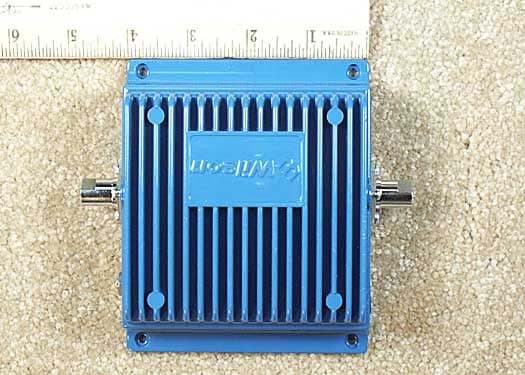
Click to zoom
Application Details
- Equipment Class
- AMP - Amplifier
- Date of Grant
- Dec 21, 2003
- Application Purpose
- Original Equipment
- Date of Application
- Dec 15, 2003
- Equipment Note
- Amps Bi-Directional Amplifier Direct
- Frequency Range
- 824.00000000 - 849.00000000
- Company
- Wilson Electronics, LLC
- Country
- United States
Documents & Files
Document Text
Text extracted from the exhibit documents filed with the FCC. Open a document above to read the original.
Users Manual
AMPS DIRECT CONNECTION AMPLIFIER Part# 811101 FCC ID: PWO824D IC: 4726A-824D iDEN DIRECT CONNECTION AMPLIFIER Part# 814001 FCC ID: PWO806D IC: 4726A-806D Installation Guide Wilson Electronics, Inc. 3301 E. Deseret Drive, St. George, Utah 84790 For additional technical support go to www.wilsonelectronics.com Phone: 1-866-294-1660 Fax: 1-435-656-2432 DIRECT CONNECTION Vehicle & Building The term “IC:” before the radio certification number only signifies that Industry of Canada technical specifications were met. 23 1. PURPOSE OF THE DIRECT CONNECTION AMPLIFIER The Direct Connection Bi-directional Amplifier improves RF coverage in areas with no signal or low signal strength. Part# 811101 Amplifies the signal on 800MHz up to 3 watts and allows for the full benefit of the outside antenna on 1900MHz frequencies. Part# 814001 Amplifies the iDEN (Nextel) frequencies up to 3 watts. 2. PACKAGE CONTENTS 2.1 Bi-directional Direct Connection Amplifier. 2.2 DC plug-in power supply with ON/OFF switch. 2.3 6ft. Adapter Extension Cable. 3. HOW THE DIRECT CONNECTION AMPLIFIER FUNCTIONS When using 800 MHz the signal is received by the outside antenna from the cell site. The signal is then AMPLIFIED and transmitted into your phone through the adapter (sold separately). When the phone transmits, the signal is sent to the amplifier through the adapter then AMPLIFIED and sent to the cell site through the outside antenna. When using 1900MHz (PCS) the signal bypasses the amplifier’s circuitry while getting full benefit from the outside antenna. NOTE: Amplifier #814001 does not have a 1900MHz (PCS) bypass as iDEN (Nextel) does not utilize this frequency. Package Contents AMPLIFIER DC PLUG-IN POWER SUPPLY 6FT ADAPTER EXTENSION CABLE 23 4. AMPLIFIER INSTALLATION (see illustration on pg.4) 4.1 Installing the Wilson Cellular Antenna 4.1.1 See antenna packaging for model specific instructions. 4.2 Installing The Amplifier 4.2.1 Select a suitable location to mount the AMPLIFIER. • In vehicle installation - under the dash or vehicle seat • In building installation - on a wall or ceiling NOTE: Mount the AMPLIFIER away from direct sunlight, excessive heat and/ or moisture. The amplifier needs proper ventilation. DO NOT place the amplifier in an air-tight enclosure. 4.2.2 Connect the outside antenna to the AMPLIFIER side labeled “OUTSIDE ANTENNA”. 4.2.3 Connect the ADAPTER EXTENSION CABLE to the AMPLIFIER side labeled “CELLULAR PHONE”. 4.2.4 An external antenna adapter is required (sold separately) to connect the AMPLIFIER to the cellphone. External antenna adapters connect directly to the antenna extension cable. 4.2.5 Connect the DC power supply to the AMPLIFIER. Verify that both the OUTSIDE ANTENNA and the ADAPTER EXTENSION CABLE are connected before powering up the AMPLIFIER. NOTE: Visit our website at www.wilsonelectronics.com for the latest adapter cross reference chart. If your phone’s adapter is not available from your retailer contact us at 1-866-294-6996 and we will help you locate one in your area. For further assistance contact our technical support Toll-Free at 866-294-1660. NOTE: iDEN Antennas are recommended for iDEN Amplifier 814001. The information provided by Wilson Electronics, Inc. is believed to be complete and accurate. However, no responsibility is assumed by Wilson Electronics, Inc. for any business or per- sonal losses arising from its use, or for any infringements of patents or other rights of third parties that may result from its use. Copyright © 2003 Wilson Electronics, Inc. 45 ����� ����������� ���������� ��������� ���� ���� �������������� ������������ ������������ ���������������� ������������������� ���� ����� ������� ������� ������������� ����� ����� ������� ���������������� �������������� ���� ���� ��������� ��������� In-Building Installation Mobile Installation 45 5. AMPLIFIER SPECIFICATIONS DIRECT CONNECTION AMPLIFIER PHYSICAL SPECIFICATIONS Connectors FME-Male 50 Ohms Dimensions 5.5x4.3x1.4 (inch) or 14.0x10.8x3.5 (cm) Weight 1.32 Pounds or 600G AMPS #811101 AMPLIFIER SPECIFICATIONS Frequency824-849MHz Uplink 869-894MHz Downlink Gain (up/down)Cell Site Controlled-Max 10/10 Flatness (up/down)(+/- 2dB / +/-2dB) Max RF (up/down)(+35dBm/+15dBm) Noise Figure (down)(3.5dB@881MHz) IsolationUplink/Downlink 90dB Power Consumption1.5A@12V iDEN #814001 AMPLIFIER SPECIFICATIONS Frequency806-821MHz Uplink 851-866MHz Downlink Gain (up/down)Cell Site Controlled-Max 10/10 Flatness (up/down)(+/- 2dB / +/-2dB) Max RF (up/down)(+35dBm/+15dBm) Noise Figure (down)(3.5dB@881MHz) IsolationUplink/Downlink 90dB Power Consumption1.5A@12V 67 6. OPTIONAL ACCESSORIES/ANTENNA OPTIONS 6.1 Coax Cable Extensions 50Ω (see chart on pg.7) 6.2 Antenna Options (see chart on pg. 8) 6.3 N-Female To FME-Female Adapter - Adapts 9913 Coax to the 811101/814001 Bi-directional Amplifier. 6.4 Lightning Suppressor (In-Building application) WARNING: Lightning protection is recommended for all In-Building installations. 6.5 Hardwire Power Supply Kit. 8. WARNINGS WARNING: Verify that both the outside antenna and adapter extension cable are connected before powering up the AMPLIFIER. WARNING: (MOBILE ONLY) The outside antenna used with this ampli- fier must be mounted with a separation distance of at least 8 inches from all persons and must not be co-located or operating in conjunction with any other antenna or amplifier. Use of a cellular amplifier with antenna gains higher than 5.12dBi is in violation of FCC regulations for which the offender is fully liable. All Wilson Mobile Antennas are 5.12dBi or less. WARNING: (IN-BUILDING ONLY) Lightning protection is recommended for all in-building installations. WARNING: (IN-BUILDING ONLY) When using in-building, the outside antenna must be fixed-mounted on an outdoor permanent structure with a separation of at least 20 feet from all persons during normal operation. Optional Accessories ������������������� ������������������ ���������������� ���������� ���������� �������� �������������� 67 7. TE…
Text truncated - open the document above for the full version.
Cover Letter(s)
November 11, 2003 Federal Communications Commission 7435 Oakland Mills Road Columbia, MD 21046 Gentlemen: This letter is to comply with section 0.457(d)(2)(i) pertaining to confidential material. Wilson Electronics, Inc. would like the following documents regarding this submission for FCC ID: PWO824D to be kept confidential. 1. CONFIDENTIAL In Line 800-DC Schematic. JPG The above material contains trade secrets or technical data, which would customarily be guarded from competitors. We do not want these documents to be accessible to the general public. Sincerely, Patrick Cook, Design Engineer Page 2
ID Label/Location Info
• 2.1033(c) (11) Label showing the information to be placed thereon. LABEL Bottom View Page 2
Operational Description
Operational Description The Direct Connection Bi-directional Amplifier Improves RF coverage for cellular phones by amplifying the receive and transmit signals.
Parts List/Tune Up Info
Tune-Up Procedure is not applicable because it is pre-set at the factory and the consumer cannot change it.
Test Report
Page 1 of 133 Report No.: FC03-066A ADDENDUM TO FC03-066 FOR THE AMPS BI-DIRECTIONAL AMPLIFIER DIRECT CONNECT, 811101 FCC PARTS 22 AND 24 AND RSS 131 COMPLIANCE DATE OF ISSUE: NOVEMBER 24, 2003 PREPARED FOR: Wilson Electronics 3301 East Deseret Drive St. George, UT 84790 PREPARED BY: Mary Ellen Clayton CKC Laboratories, Inc. 5473A Clouds Rest Mariposa, CA 95338 P.O. No.: BD800ADC-FCC-10-2 W.O. No.: 81209 Date of test: October 13 - November 10, 2003 Report No.: FC03-066A This report contains a total of 133 pages and may be reproduced in full only. Partial reproduction may only be done with the written consent of CKC Laboratories, Inc. The results in this report apply only to the items tested, as identified herein. Page 2 of 133 Report No.: FC03-066A TABLE OF CONTENTS Administrative Information .............................................................................................3 Summary of Results .........................................................................................................4 Conditions for Compliance ..............................................................................................4 Approvals .........................................................................................................................4 Equipment Under Test (EUT) Description ......................................................................5 Equipment Under Test .....................................................................................................5 Peripheral Devices ...........................................................................................................5 Measurement Uncertainty ................................................................................................5 Temperature and Humidity During Testing.....................................................................6 FCC 2.1033(c)(3) User’s Manual ....................................................................................6 FCC 2.1033(c)(4) Type of Emissions ..............................................................................6 FCC 2.1033(c)(5) Frequency Range................................................................................6 FCC 2.1033(c)(6) Operating Power.................................................................................6 FCC 2.1033(c)(7) Maximum Power Rating ....................................................................6 FCC 2.1033(c)(8) DC Voltages .......................................................................................6 FCC 2.1033(c)(9) Tune-Up Procedure ............................................................................6 FCC 2.1033(c)(10) Schematics and Circuitry Description..............................................6 FCC 2.1033(c)(11) Label and Placement ........................................................................6 FCC 2.1033(c)(12) Submittal Photos ..............................................................................6 FCC 2.1033(c)(13) Modulation Information ...................................................................6 FCC 2.1033(c)(14)/2.1046/22.913 - RF Power Output ...................................................7 FCC 2.1033(c)(14)/2.1051/22.917 - Spurious Emissions at Antenna Terminal..............10 FCC 2.1033(c)(14)/2.1053/22.917 - Field Strength of Spurious Radiation ....................63 FCC 24.238 - Spurious Emissions at Antenna Terminal .................................................68 FCC 2.1051 - Intermodulation Attenuation .....................................................................72 FCC 2.1091 - MPE Calculations .....................................................................................85 Downlink Input Plots .......................................................................................................87 Uplink Input Plots ............................................................................................................97 Downlink Output Plots ....................................................................................................107 Uplink Output Plots .........................................................................................................117 RSS 131 20 dB Passband Downlink ................................................................................128 RSS 131 20 dB Passband Gain 0-20 Downlink...............................................................129 RSS 131 20 dB Passband Uplink.....................................................................................130 RSS 131 20 dB Passband Gain 0-20 Uplink....................................................................131 RSS 131 20 dB Passband Gain 20-40 Uplink..................................................................132 Page 3 of 133 Report No.: FC03-066A ADMINISTRATIVE INFORMATION DATE OF TEST: October 13 - November 10, 2003 DATE OF RECEIPT: October 13, 2003 PURPOSE OF TEST: To demonstrate the compliance of the Amps Bi- Directional Amplifier Direct Connect, 811101 with the requirements for FCC Parts 22 and 24 and RSS 131 devices. Addendum A revised the frequency range on page 6, moved the intermodulation data sheets next to the plots, revised the Part 24 and 2.1053 test conditions and added test conditions for the input and output plots. TEST METHOD: FCC Parts 22 and 24 and RSS 131 FREQUENCY RANGE TESTED: 30 MHz – 10 GHz MANUFACTURER: Wilson Electronics 3301 East Deseret Drive St. George, UT 84790 REPRESENTATIVE: Patrick Cook TEST LOCATION: CKC Laboratories, Inc. 5473A Clouds Rest Mariposa, CA 95338 Page 4 of 133 Report No.: FC03-066A SUMMARY OF RESULTS As received, the Wilson Electronics Amps Bi-Directional Amplifier Direct Connect, 811101 was found to be fully compliant with the following standards and specifications: Canadian Standard Canadian Section FCC Standard FCC SectionTest Description RSS 1315.4N/AN/AExternal Controls RSS 1315.547 CFR1.1307RF Exposure RSS 1316.1N/AN/APassband …
Text truncated - open the document above for the full version.
Test Setup Photos
Direct Connect Radiated Emissions with 13 dBi Yagi Antenna PHOTOGRAPH SHOWING RADIATED EMISSIONS Radiated Emissions with 5 dBi Whip Antenna PHOTOGRAPH SHOWING RADIATED EMISSIONS Radiated Emissions with Downlink RF Port Terminated
Contact Information
Applicant
Mikel Parry(Compliance Manager)
Technical Contact
CKC Laboratories, Inc.Mary Ellen Clayton
[email protected]800-500-4362
5473-A Clouds Rest · Mariposa, California · United States
Non-Technical Contact
CKC Laboratories, Inc.Mary Ellen Clayton
[email protected]800-500-4362
Test Firm
CKC Laboratories, Inc.Steve Behm
Technical Specifications
| # | Rule Parts | Frequency Range | Power Output | Emission | Tolerance |
|---|---|---|---|---|---|
| 8 | 22 | 824 MHz - 849 MHz | 1 W | F1D | Amp |
Other Applications from Wilson Electronics, LLC
PWO086
Mar 09, 2026Single Band Bi-Directional Amplifier
Equipment Class
B2W - Part 20 Wideband Consumer Booster (CMRS)PWO072
Aug 26, 20245G NR Industrial Signal Booster
Equipment Class
B2I - Part 20 Industrial Booster (CMRS)
PWO075
Jan 10, 2024Quint Band Signal Booster
Equipment Class
B2W - Part 20 Wideband Consumer Booster (CMRS)
PWO460065
Nov 04, 2020Dual Band Signal Booster
Equipment Class
B2W - Part 20 Wideband Consumer Booster (CMRS)
PWO460061
Sep 22, 2020Quint Band Signal Booster
Equipment Class
B2W - Part 20 Wideband Consumer Booster (CMRS)