PXK-HL2506Speaker Duo
ECORE TECHNOLOGY COMPANY LIMITED
Click to zoom
Application Details
- Equipment Class
- DSS - Part 15 Spread Spectrum Transmitter
- Date of Grant
- Jul 27, 2014
- Application Purpose
- Original Equipment
- Date of Application
- Jul 27, 2014
- Equipment Note
- Speaker Duo
- Frequency Range
- 2402.00000000 - 2480.00000000
- Country
- China
Documents & Files
Document Text
Text extracted from the exhibit documents filed with the FCC. Open a document above to read the original.
Users Manual
1 / 5 Speaker Duo User’s Manual Product overview Thank you for purchasing the bem wireless Speaker Duo. Our speaker will bring you a new found freedomfrom wires while delivering an incredible sound. The Speaker Duo is compatible with all devices enabled withBluetooth© technology... which is currently a lot of devices! Make sure to read through the following directions, fully charge your device and perform the initialBluetooth© syncing process and you should be up and running in no time. If you have any problems stop onby bemwireless.com for the answers to all your questions. Package contents z Matrix Case x 1 z Satellite Speaker x 2 z Power adapter x 1 z Aux cable x 1 z User’s Manual x 1 If any of these were missing or damaged, please visit bemwirelesss.com to obtain replacement. Compatibility z All devices enabled with Bluetooth technology, including iPhones, iPads, iPods, smartphones, laptops, tablets and more; z Also compatible with any device that has a standard 3.5mm earphone jack such as MP3 players, PSP, mobile phones, etc. Meet the Speaker Duo Before learning your Speaker Duo, take a moment to look it over and familiarize yourself with its features. The Matrix Case (1) Volume – (2) Power / Pair (3) Volume + (4) Bluetooth© Indicator (5) Aux In (6) DC In (7) Charging Indicator (8) Connection Indicator (9) Handle 2 / 5 The Satellite Speaker Getting Started We know you are excited to experience your new Speaker Duo. These two easy steps will get youup and running quickly. Step 1: Charge It Connect your Speaker Duomatrix case to an outlet using the included power adapter. It will start charging the matrix case. Slide the satellitespeakers intothe case for charging. The red backlight will slowly flash during charging and goes out when it hasreached a complete charge (Approx. 3.5 hours). Step 2: Connect it There are two options for connecting to your Speaker Duo ‐ wirelessly by Bluetooth© or wired using theincluded aux cable. z Connect Wirelessly Turn on the power of the matrix case followed by powering on each of the 2 satellitespeakers. Once the base is powered on the Bluetooth© indicator will lightand a tone confirming that the unit is currently in paring mode will sound. Go to the Bluetooth© settings on your mobile phone, tablet or computerto find the device named “Speaker Duo”. A tone will sound to confirm thedevice has paired successfully. Next time the Speaker Duo and connecteddevice will pair automatically. After completing this step you are ready tostart playing audio from your connected device. Hold the Play/Pause button for 5 seconds will disconnect the connected device and enter pairing mode for pairing a new device. z Direct Connection The Speaker Duo can also be connected to any device that has aheadphone jack or line out using the included aux cable. Please note the play/pause button only operates when connected via Bluetooth©. (1) Speaker Driver (2) L/R switch (3) Charging & Connection Indicator (4) Power / Pair (5) Charging Pin 3 / 5 Operation Details Power on / Power off Matrix Case: Press the power button to turn on the Matrix Case of Speaker Duo. The Bluetooth© indicator will light up to signify the unit is on and ready to be paired. Press the power button again to turn off the base and the Bluetoothindicator light will go out. SatelliteSpeakers: Press the power button to turn the speaker on. The Indicator on the speaker will light up to signify the unit is on. Press the power button again to turn off the speaker and the Indicatorwill also go out. Please note, always make sure to first turn on the base unit before turning on the speakers Play modes Bluetooth mode: play an audio signal from theconnected Bluetooth© device. AUX mode: play an audio signal from the connected"wired" device. Please note, if an Aux cable is connected to thespeaker it will not play music from Bluetooth©connected devices. Select the L/R Channel Use the L/R switch at the back of the Satellite Speakerto select the sound channel. Switch to L toplay left channel and R for right channel. Audio Use Follow the above connection steps to pair aBluetooth© device with the Speaker Duo. At thispoint you can send any kind of audio signal to yourspeaker (music, video, gaming, etc.). Just use yourdevice as normal and the audio will play through yourSpeaker Duo. Controls Press the Power/Pair button to play or pause themusic when using a music player through yourBluetooth© connected device. Pressing the + and ‐ buttons will increase or decreasethe volume on the Speaker Duo. Please note thatthis will not affect the volume levels on the connecteddevice. Connection Laptop / notebook / PC As the Bluetooth© versions for these types of devicesvaries greatly, the connection methods will differ aswell. If you can not connect with the Speaker Duousing the previous method instructed you may needto install a new version of the Bluetooth© driver. Please reference the instructions of device for details. Speaker Placement The Satellitematrix casehas battery built‐in, with the metal handle, it can be take easily on the go. The 2 individual speakers can be removed from the matrix case to be set anywhere you like. Approximate range is 50ft away from the case (open area). The Speaker Duo uses 5.8gHz signal so you're free to putthe speakers where you like! Charging Connect your matrix case to an outlet using the included power adapter. Place the speakers into the charging area of the case. The red backlight will slowly flash during charging and goes out when it has reached a complete charge (Approx. 3.5 hours). Note: if the unit has not been used in the past 7 days please charge for 10 minutes before using the Speaker Duo. Troubleshooting Issue: Pairing is unsuccessfully after multiple attempts Solution: z Check if the Bluetooth© indicator light is on. If the indicator light is off, please press the power button toturn the unit on. If the Bluetooth© indicator light still doesn’t come on after pressing the power button,please char…
Text truncated - open the document above for the full version.
Cover Letter(s)
SCS-F18: Project and Product Certification Representative Authorization Letter Page 1 of 2 Rev 4.0 775 Montague Expressway Milpitas, CA 95035 Tel: 408-526-1188 Fax: 408-526-1088 Email: [email protected] Project and Product Certification Representative Authorization Letter Revision History Reason for Amendment (current / obsolete) From To Approved Date Initial Release (obsolete) 1.0 1.0 Nov-14-2006 Revised wording (obsolete) 1.0 2.0 Sept–25-2007 Updated company template (obsolete) 2.0 3.0 Jan-31-2012 Updated letter information (current) 3.0 4.0 May-23-2014
Cover Letter(s)
SCS-F19: Confidentiality Request Letter Page 1 of 2 Rev 3.0 775 Montague Expressway Milpitas, CA 95035 Tel: 408-526-1188 Fax: 408-526-1088 Email: [email protected] Confidentiality Request Letter Revision History Reason for Amendment (current / obsolete) From To Approved Date Initial Release (obsolete) 1.0 1.0 Nov-14-2006 Adding CFR 2.459 (obsolete) 1.0 2.0 August – 11 - 2008 Updated company template & Added text box (current) 2.0 3.0 Jan-31-2012
External Photos
Dongguan Nore Testing Center Co., Ltd. Report No.: NTC1405647F/-1/-2 FCC ID: PXK-HL2506 Dongguan Nore Testing Center Co., Ltd. Report No.: NTC1405647F/-1/-2 FCC ID: PXK-HL2506 Dongguan Nore Testing Center Co., Ltd. Report No.: NTC1405647F/-1/-2 FCC ID: PXK-HL2506 Dongguan Nore Testing Center Co., Ltd. Report No.: NTC1405647F/-1/-2 FCC ID: PXK-HL2506 Dongguan Nore Testing Center Co., Ltd. Report No.: NTC1405647F/-1/-2 FCC ID: PXK-HL2506 Dongguan Nore Testing Center Co., Ltd. Report No.: NTC1405647F/-1/-2 FCC ID: PXK-HL2506 Dongguan Nore Testing Center Co., Ltd. Report No.: NTC1405647F/-1/-2 FCC ID: PXK-HL2506 Dongguan Nore Testing Center Co., Ltd. Report No.: NTC1405647F/-1/-2 FCC ID: PXK-HL2506 Dongguan Nore Testing Center Co., Ltd. Report No.: NTC1405647F/-1/-2 FCC ID: PXK-HL2506
ID Label/Location Info
Label Location
Internal Photos
Dongguan Nore Testing Center Co., Ltd. Report No.: NTC1405647F/-1/-2 FCC ID: PXK-HL2506 Dongguan Nore Testing Center Co., Ltd. Report No.: NTC1405647F/-1/-2 FCC ID: PXK-HL2506 Dongguan Nore Testing Center Co., Ltd. Report No.: NTC1405647F/-1/-2 FCC ID: PXK-HL2506 5.8G Chip 5.8G Antenna Dongguan Nore Testing Center Co., Ltd. Report No.: NTC1405647F/-1/-2 FCC ID: PXK-HL2506 Dongguan Nore Testing Center Co., Ltd. Report No.: NTC1405647F/-1/-2 FCC ID: PXK-HL2506 Dongguan Nore Testing Center Co., Ltd. Report No.: NTC1405647F/-1/-2 FCC ID: PXK-HL2506 5.8G Chip 5.8G Antenna BT Chip BT Antenna Dongguan Nore Testing Center Co., Ltd. Report No.: NTC1405647F/-1/-2 FCC ID: PXK-HL2506 Dongguan Nore Testing Center Co., Ltd. Report No.: NTC1405647F/-1/-2 FCC ID: PXK-HL2506
RF Exposure Info
DONGGUAN NTC CO., LTD. FCC ID: PXK-HL2506 Report No.: NTC1405647F/-1/-2 RF EXPOSURE EVALUATION EUT Specification EUT Speaker Duo Frequency band (Operating) WLAN: 2.412GHz ~ 2.462GHz WLAN: 5.18GHz ~ 5.32GHz / 5.50GHz ~ 5.70GHz WLAN: 5.745GHz ~ 5825GHz Others(Bluetooth: 2.402GHz ~ 2.480GHz) Device category Portable (<20cm separation) Mobile (>20cm separation) Others ___ Antenna diversity Single antenna Multiple antennas Tx diversity Rx diversity Tx/Rx diversity Max. output power -1.66dBm (0.68mW) For BT 2.1+EDR 4.81dBm (3.03mW) For BLE Antenna gain -0.61 dBi Evaluation applied MPE Evaluation SAR Evaluation Standard Requirement Portable Device According to §15.247(i) and §1.1307b(1), systems operating under the provisions of this section shall be operated in a manner that ensures that the public is not exposed to radio frequency energy levels in excess of the Commission’s guidelines. See KDB 447498 D01 General RF Exposure Guidance v05, section 4.3.1. The 1-g and 10-g SAR test exclusion thresholds for 100 MHz to 6 GHz at test separation distances ≤ 50 mm are determined by: [(max. power of channel, including tune-up tolerance, mW)/(min. test separation distance, mm)] ·[√f(GHz)] ≤ 3.0 for 1-g SAR and ≤ 7.5 for 10-g extremity SAR, 16 where ·f(GHz) is the RF channel transmit frequency in GHz ·Power and distance are rounded to the nearest mW and mm before calculation17 ·The result is rounded to one decimal place for comparison The test exclusions are applicable only when the minimum test separation distance is ≤ 50 mm and for transmission frequencies between 100 MHz and 6 GHz. When the minimum test separation distance is < 5 mm, a distance of 5 mm is applied to determine SAR test exclusion. DONGGUAN NTC CO., LTD. FCC ID: PXK-HL2506 Report No.: NTC1405647F/-1/-2 Measurement Result For BT 2.1+EDR Channel Channel Frequency (MHz) Max Output AVG power (dBm) Max Output AVG power (mW) Calculation Value (Note 1) Threshold Value GFSK Low 2402.00 -4.18 0.38 0.12 3.0 Middle 2441.00 -2.36 0.58 0.18 3.0 High 2480.00 -2.67 0.54 0.17 3.0 π/4-DQPSK Low 2402.00 -4.18 0.38 0.12 3.0 Middle 2441.00 -2.37 0.58 0.18 3.0 High 2480.00 -2.70 0.54 0.17 3.0 8DPSK Low 2402.00 -3.50 0.45 0.14 3.0 Middle 2441.00 -1.66 0.68 0.21 3.0 High 2480.00 -1.98 0.63 0.20 3.0 For BT 4.0 Channel Channel Frequency (MHz) Max Output AVG power (dBm) Max Output AVG power (mW) Calculation Value (Note 1) Threshold Value Low 2402.00 3.50 2.24 0.69 3.0 Middle 2442.00 4.51 2.82 0.88 3.0 High 2480.00 4.81 3.03 0.95 3.0 Note 1: Calculation Value =[(max. power of channel, mW)/(min. test separation distance, mm)] ·[√f(GHz)]. Fox example: 0.38/5*√2.402=0.12 ≤ 3.0 According to KDB447498 D01 v05, threshold at which no SAR required is ≤3.0 for 1-g SAR, separation distance is 5mm, and no simultaneous SAR measurement is required.
Test Report
Page 1 of 58 Dongguan Nore Testing Center Co., Ltd. Report No.: NTC1405647F FCC ID: PXK-HL2506 Page 2 of 58 Table of Contents 1. GENERAL INFORMATION ................................................................................................ 4 1.1 P RODUCT D ESCRIPTION FOR E QUIPMENT UNDER T EST .................................................................... 4 1.2 R ELATED S UBMITTAL ( S ) / G RANT ( S )................................................................................................ 6 1.3 T EST M ETHODOLOGY ...................................................................................................................... 6 1.4 E QUIPMENT M ODIFICATIONS ............................................................................................................ 6 1.5 S UPPORT D EVICE ............................................................................................................................ 6 1.6 T EST F ACILITY AND L OCATION .......................................................................................................... 6 1.7 S UMMARY OF T EST R ESULTS ........................................................................................................... 7 2. SYSTEM TEST CONFIGURATION .................................................................................... 8 2.1 EUT C ONFIGURATION ...................................................................................................................... 8 2.2 S PECIAL A CCESSORIES .................................................................................................................... 8 2.3 D ESCRIPTION OF TEST MODES ......................................................................................................... 8 2.4 EUT E XERCISE ................................................................................................................................8 3. CONDUCTED EMISSIONS TEST ...................................................................................... 9 3.1 T EST SET-UP (B LOCK D IAGRAM OF C ONFIGURATION )..................................................................... 9 3.2 T EST C ONDITION ............................................................................................................................. 9 3.3 M EASUREMENT R ESULTS ................................................................................................................. 9 4. RADIATED EMISSION TEST........................................................................................... 12 4.1 T EST SET-UP (B LOCK D IAGRAM OF C ONFIGURATION )................................................................... 12 4.2 M EASUREMENT P ROCEDURE ......................................................................................................... 13 4.3 L IMIT .............................................................................................................................................. 13 4.4 M EASUREMENT R ESULTS ..................................................................................................... 15 5. CHANNEL SEPARATION TEST ...................................................................................... 19 5.1 M EASUREMENT P ROCEDURE ......................................................................................................... 19 5.2 T EST SET-UP (B LOCK D IAGRAM OF C ONFIGURATION )................................................................... 19 5.3 M EASUREMENT R ESULTS ............................................................................................................... 19 6. 20DB BANDWIDTH.......................................................................................................... 25 6.1 M EASUREMENT P ROCEDURE ......................................................................................................... 25 6.2 T EST SET-UP (B LOCK D IAGRAM OF C ONFIGURATION )................................................................... 25 6.3 M EASUREMENT R ESULTS ............................................................................................................... 25 7. HOPPING CHANNEL NUMBER ...................................................................................... 26 7.1 M EASUREMENT P ROCEDURE ......................................................................................................... 31 7.2 T EST SET-UP (B LOCK D IAGRAM OF C ONFIGURATION )................................................................... 31 7.3 M EASUREMENT R ESULTS ............................................................................................................... 31 Dongguan Nore Testing Center Co., Ltd. Report No.: NTC1405647F FCC ID: PXK-HL2506 Page 3 of 58 8. TIME OF OCCUPANCY (DWELL TIME).......................................................................... 33 8.1 M EASUREMENT P ROCEDURE ......................................................................................................... 33 8.2 M EASUREMENT R ESULTS ............................................................................................................... 33 9. MAXIMUM PEAK OUTPUT POWER ............................................................................... 33 9.1 M EASUREMENT P ROCEDURE ......................................................................................................... 39 9.2 M EASUREMENT R ESULTS ............................................................................................................... 39 10. BAND EDGE ..................................................................................................................39 10.1 M EASUREMENT P ROCEDURE ....................................................................................................... 45 10.2 L IMIT ............................................................................................................................................ 45 10.3 M EASU…
Text truncated - open the document above for the full version.
Test Setup Photos
Dongguan Nore Testing Center Co., Ltd. Report No.: NTC1405647F/-1/-2 FCC ID: PXK-HL2506 Conducted Emission Dongguan Nore Testing Center Co., Ltd. Report No.: NTC1405647F/-1/-2 FCC ID: PXK-HL2506 Radiated Emission
Contact Information
Applicant
Liucheng Liu(Manager)
Test Firm
Dongguan NTC Co.,Ltd.,sunm lv sunm lv
[email protected]86-769-22022444
Technical Specifications
| # | Rule Parts | Frequency Range | Power Output |
|---|---|---|---|
| 1 | 15C | 2.40 GHz - 2.48 GHz | 680.00 µW |
Other Applications from ECORE TECHNOLOGY COMPANY LIMITED
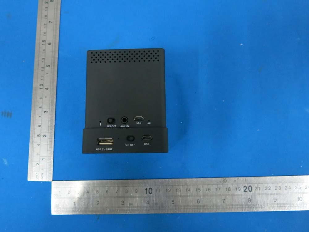
PXK-HL2750
Oct 31, 2015Speaker Mojo II
Equipment Class
DSS - Part 15 Spread Spectrum Transmitter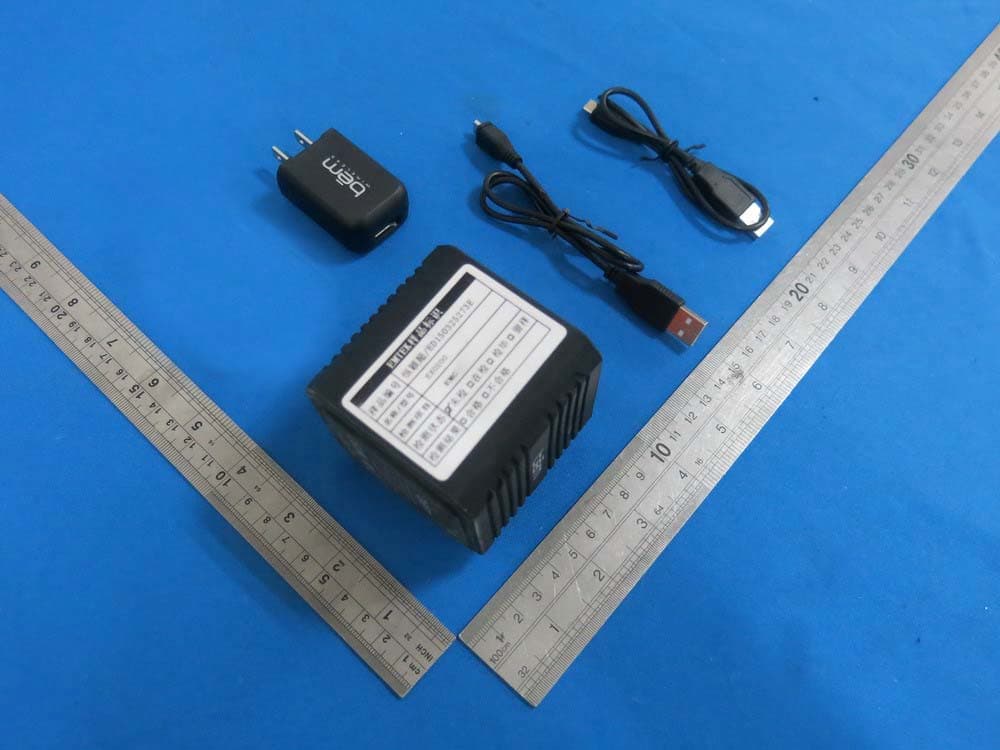
PXK-EXO200
Jul 01, 2015EXO-200
Equipment Class
DTS - Digital Transmission System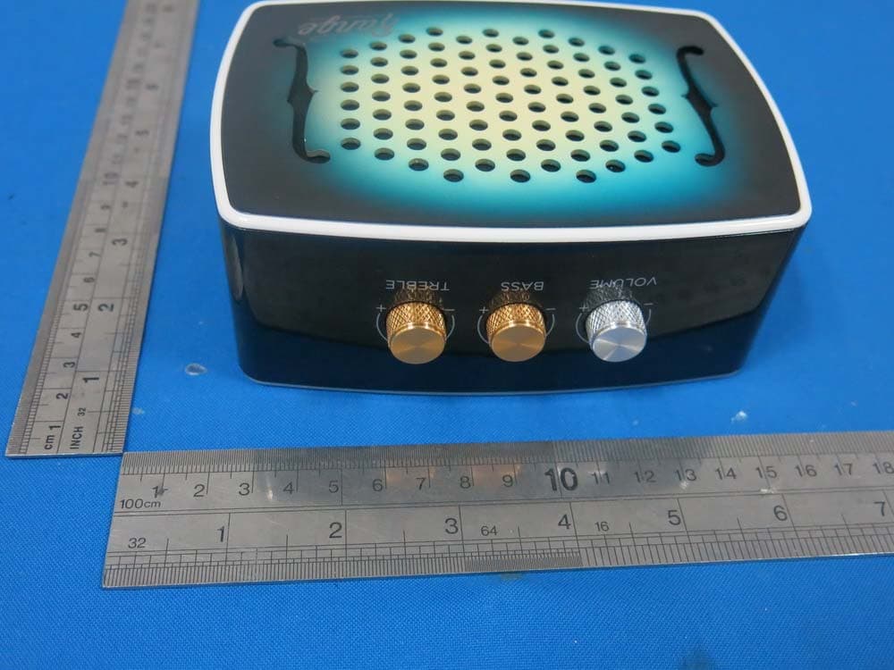
PXK-HL2515
Dec 22, 2014Strum
Equipment Class
DTS - Digital Transmission System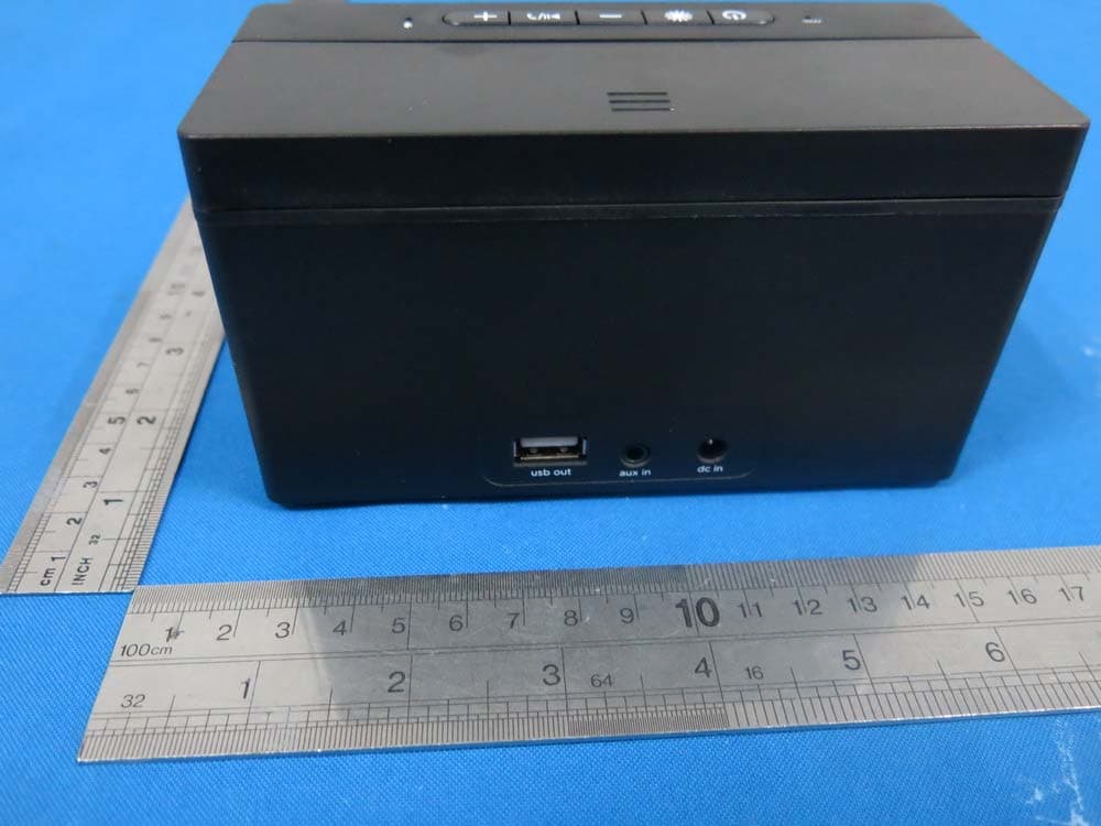
PXK-HL2507
Dec 22, 2014Express Speaker
Equipment Class
DTS - Digital Transmission System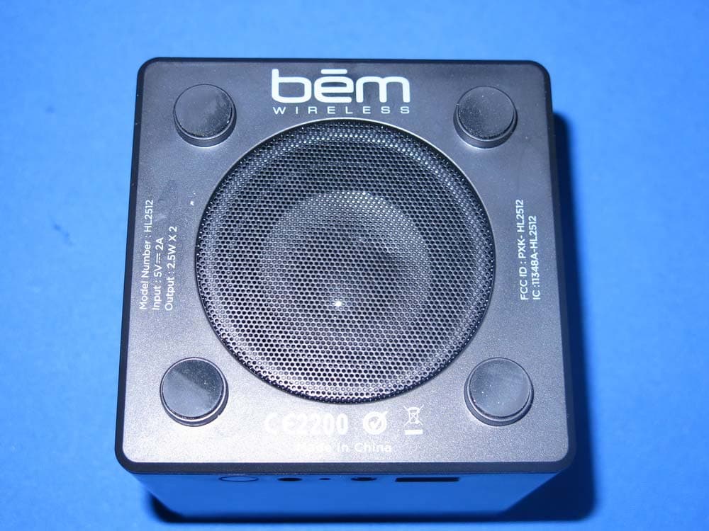
PXK-HL2512
Dec 22, 2014Eclipse
Equipment Class
DSS - Part 15 Spread Spectrum Transmitter