PXK-HL2750Speaker Mojo II
ECORE TECHNOLOGY COMPANY LIMITED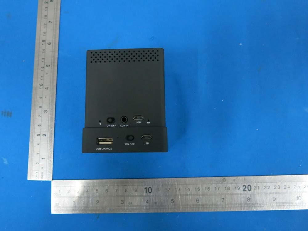
Click to zoom
Application Details
- Equipment Class
- DSS - Part 15 Spread Spectrum Transmitter
- Date of Grant
- Oct 31, 2015
- Application Purpose
- Original Equipment
- Date of Application
- Oct 31, 2015
- Equipment Note
- Speaker Mojo II
- Frequency Range
- 2402.00000000 - 2480.00000000
- Country
- China
Documents & Files
Document Text
Text extracted from the exhibit documents filed with the FCC. Open a document above to read the original.
Users Manual
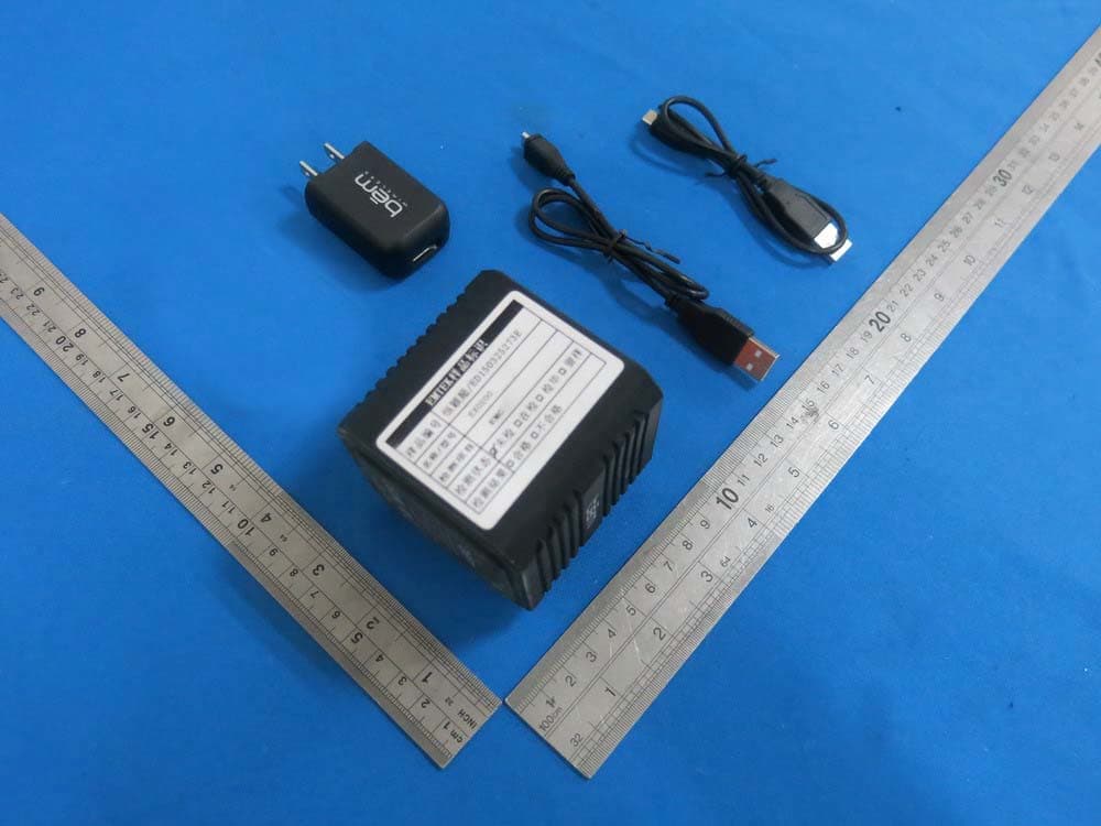
II 2 Product Overview In order to make sure you get the best possible results from your new Speaker Mojo II, please thoroughly read and carefully follow all instructions in this User’s Manual or on the product. Keep this User’s Manual in a convenient location for future reference. Package Contents: Speaker Mojo II x 1 Power cradle x 1 Power adapter x 1 Micro USB charging cable x 1 Aux cable x 1 User’s Manual x 1 If any of the above contents were missing or damaged, please visit bemwireless.com/support/ to obtain a replacement. Please do not return to Club, please call 855-839-8616 if you have any questions or issues with the Speaker Mojo II. Compatibility All devices enabled with Bluetooth technology, including iPhones, iPads, iPods, smartphones, laptops, tablets and more. Also compatible with any device that has a standard 3.5mm earphone jack such as MP3 players, PSP, mobile phones, etc. Meet the Speaker Mojo II Before learning about your Speaker Mojo II, take a moment to look it over and familiarize yourself with its features. M L R 15 3 Product Interface 1. Microphone 2. Volume + 3. Volume – 4. Play / Pause /Speak- erphone 5. Power Cradle 6. On/ Off switch 7. Bluetooth © indicator 8. Aux in 9. Micro USB power port 10. Power indicator Power Cradle 11. USB port 12. Power Indicator 13. Charging switch 14. Micro USB power port Stereo Function 15. Stereo (L, M, R) Switch Speaker Mojo II Important: Select Speaker mode prIor to turnIng on Speaker(S) 4 Charging Modes 1. Direct Speaker Charge Connect the standard USB end of the supplied USB cable to a USB power source (PC, USB power adapter...etc.). Connect the Micro USB jack to the USB charging port on the Speaker Mojo II. It will take about 2 hours to fully charge the Speaker Mojo II alone. Charging Indicator Light Modes Power indicator on Speaker Mojo II •Red LED: Speaker Mojo II is charging; •No LED: Battery is fully charged •Note: When the battery is low, you will hear a tone signaling you to charge the unit soon 2. Power Cradle Charge The Power cradle is a backup battery pack for Speaker Mojo II and your Bluetooth device. Connect the standard USB end of the supplied USB cable to a USB power source (PC, USB power adapter...etc.). Connect the Micro USB jack to the USB charging port on the power cradle. The charging indicator will light up while charging. It will take about 3 hours to fully charge the power cradle. Important: Select Speaker mode prIor to turnIng on Speaker(S) 5 Indicator on power cradle •Red LED : Charging, it will go off when it is fully charged; •Blue LED : power output is on. 3. Wireless Conductive Charging via Power Cradle Connect the standard USB end of the supplied USB cable to a USB power source (PC, USB power adapter... etc.). Connect the Micro USB jack to the USB charging port on the power cradle. The charging indicator will light up while charging. If you put Speaker Mojo II onto the power cradle, it will charge them both at the same time whether you connect the power to the Speaker Mojo II or power cradle. It will take about 5 hours for charging them at the same time. Once both are fully charged, the battery life of the Speaker Mojo II can be doubled. This can be done by turning on the power cradle, placing the Speaker Mojo II on the cradle and turning it on while playing music. Please note, the Speaker Mojo II LED charging indicator will not light up when the speaker is charging on the Power Cradle Charging Modes (Cont.) Important: Select Speaker mode prIor to turnIng on Speaker(S) 6 4. Charging Other USB Enabled Devices via Power Cradle The included Power Cradle can also be used to charge other USB enabled devices. Simply follow the steps listed in number 2 to charge up the Power Cradle. You can now take the power cradle with you on the go to charge various other smart devices via USB. You can do so by connecting the standard USB end of a USB cable to the USB port in the back of the Power Cradle. Then plug the other end into your smart device. Slide the power switch to “on” to turn it on and begin charging other smart devices. The blue indicator light will light up to signify the unit is on.Slide the power switch to “off” to turn off the power cradle. The blue indicator light will go out and your smart devices will no longer charge via USB. Speaker Selection (Mode) Important: Before you go to turn on the Speaker Mojo II please stop and read these instructions carefully. The Speaker Mojo II can be played in a couple of different ways. Mono mode will allow you to work with just one speaker or stereo mode which allows you to pair up two speakers. Charging Modes (Cont.) Play Modes Important: Select Speaker mode prIor to turnIng on Speaker(S) 7 Playing in Mono Mode: Make sure the switch on the bottom of the speaker is switched to “M” before turning on the speaker Playing in Stereo Mode: One speaker must be switched to “L” on the bottom and the other must be switched to “R” before turning them on. Power on / Power off Slide the power switch to “on” to turn on the Speaker Mojo II. The Bluetooth indicator will light up blue to signify the unit is on and ready to be paired. Slide the power switch to “off” to turn off the unit and the Bluetooth indicator light will go out. Play Modes (Cont.) M L R M LR M L R M LR M L R M LR Important: Select Speaker mode prIor to turnIng on Speaker(S) 8 Single Speaker •Bluetooth mode: Play an audio signal from the connected Bluetooth device. Before turning the Speaker Mojo II on, turn the speaker over so that the bottom of the speaker is facing up. Locate the stereo switch (L,M,R) on the speaker and make sure that it is set to the “M” or mono setting. •Now turn on the Speaker Mojo II. Once the Speaker Mojo II has entered Bluetooth mode, the Bluetooth icon will light up blue and the tone confirming that the unit is currently in Bluetooth pairing mode will sound. •Go to the Bluetooth settings on your smart device to find the device named “Mojo II”. A tone will sound to confirm the device h…
Text truncated - open the document above for the full version.
Cover Letter(s)
SCS-F18: Project and Product Certification Representative Authorization Letter Page 1 of 2 Rev 5.0 775 Montague Expressway Milpitas, CA 95035 Tel: 408-526-1188 Fax: 408-526-1088 Email: [email protected] Project and Product Certification Representative Authorization Letter Reason for Amendment (current / obsolete) Revision History Approved Date From To Initial Release (obsolete) 1.0 1.0 Nov-14-2006 Revised wording (obsolete) 1.0 2.0 Sept–25-2007 Updated company template (obsolete) 2.0 3.0 Jan-31-2012 Updated letter information (obsolete) 3.0 4.0 May-23-2014 Added FCC ID field (current) 4.0 5.0 Sept 16 2014 SCS-F18: Project and Product Certification Representative Authorization Letter Page 2 of 2 Rev 5.0 ECORE TECHNOLOGY COMPANY LIMITED (2015-10-27) To: SIEMIC, INC. 775 Montague Expressway, Milpitas, CA 95035 USA Dear Sir/Madam, Re: Product Certification Representative Authorization Letter We, _____ ECORE TECHNOLOGY COMPANY LIMITED _____hereby authorize SIEMIC, Inc. to act as a Certification Body for certifying for the following project(s): Product Name: Speaker Mojo II Model Number: HL2750 FCC ID: PXK-HL2750 Sincerely, Liuchengliu Manager North of Bingang East Road, Huahu Development Zone, Ezhou city, Hubei Province, China
Cover Letter(s)
SCS-F19: Confidentiality Request Letter Page 1 of 2 Rev 4.0 775 Montague Expressway Milpitas, CA 95035 Tel: 408-526-1188 Fax: 408-526-1088 Email: [email protected] Confidentiality Request Letter Reason for Amendment (current / obsolete) Revision History Approved Date From To Initial Release (obsolete) 1.0 1.0 Nov-14-2006 Adding CFR 2.459 (obsolete) 1.0 2.0 August – 11 - 2008 Updated company template & Added text box (obsolete) 2.0 3.0 Jan-31-2012 Added IC confidentiality letter form (current) 3.0 4.0 March-26-2015 SCS-F19: Confidentiality Request Letter Page 2 of 2 Rev 4.0 ECORE TECHNOLOGY COMPANY LIMITED (2015-10-27) To: Federal Communications Commission Authorization and Evaluation Division 7435 Oakland Mills Road Columbia, MD Subject: Permanent Confidentiality Request for FCC ID: PXK-HL2750 We hereby request confidential treatment of information accompanying this application as outlined below: - Block Diagram - Schematics - Operational Description The above materials contain trade secrets and proprietary information not customarily released to the public. The public disclosure of these materials may be harmful to the applicant and provide unjustified benefits to its competitors. The applicant understands that pursuant to Section 0.457 & 0.459 of the Rules, disclosure of this application and all accompanying documentation will not be made before the date of the Grant for this application. Sincerely, Liuchengliu Manager North of Bingang East Road, Huahu Development Zone, Ezhou city, Hubei Province, China
ID Label/Location Info
丝产产 丝产产 丝产产 USB ON OFF AUX IN USB ON OFF AUX IN M L R Made in China Model Number: HL2750 Input: USB5V 1A Li-ion battery: 3.7V 600mAh Output: 1.5W X 2 FCC ID: PXK-HL2750 USB CHARGE ON OFF USB USB CHARGE ON OFF USB Made in China Model Number: HL2750 Input: USB5V 1A Li-ion battery: 3.7V 1800mAh Output: USB5V 1A FCC ID: PXK-HL2750 IC: 11348A-HL2750 CAN ICES-003(B)/ NMB-3(B) Made in China Model Number: HL2750 Input: USB5V 1A Li-ion battery: 3.7V 1800mAh Output: USB5V 1A FCC ID: PXK-HL2750 IC: 11348A-HL2750 CAN ICES-003(B)/ NMB-3(B) IC: 11348A-HL2750CAN ICES-003(B)/ NMB-3(B) M L R Made in China Model Number: HL2750 Input: USB5V 1A Li-ion battery: 3.7V 600mAh Output: 1.5W X 2 FCC ID: PXK-HL2750 IC: 11348A-HL2750CAN ICES-003(B)/ NMB-3(B)
ID Label/Location Info
Label Location on EUT
Internal Photos
Antenna
RF Exposure Info
RF EXPOSURE EVALUATION According to FCC 1.1310: The criteria listed in the following table shall be used to evaluate the environment impact of human exposure to radio frequency(RF) Radiation as specified in §1.1307(b) FCC ID:PXK-HL2750 EUT Specification EUT Speaker Mojo II Frequency band (Operating) WLAN: 2.412GHz ~ 2.462GHz WLAN: 5.18GHz ~ 5.32GHz / 5.50GHz ~ 5.70GHz WLAN: 5.745GHz ~ 5825GHz Others Device category Portable (<20cm separation) Mobile (>20cm separation) Others ___ Exposure classification Occupational/Controlled exposure (S = 5mW/cm2) General Population/Uncontrolled exposure (S=1mW/cm2) Antenna diversity Single antenna Multiple antennas Tx diversity Rx diversity Tx/Rx diversity Max. output power -0.74dBm(0.000843W) Antenna gain (Max) 0 dBi Evaluation applied MPE Evaluation SAR Evaluation Limits for Maximum Permissible Exposure(MPE) Frequency Range(MHz) Electric Field Strength(V/m) Magnetic Field Strength(A/m) Power Density(mW/cm 2 ) Average Time (A) Limits for Occupational/Control Exposures 300-1500 -- -- F/300 6 1500-100000 -- -- 5 6 (B) Limits for General Population/Uncontrol Exposures 300-1500 -- -- F/1500 6 1500-100000 -- -- 1 30 Friis transmission formula: Pd=(Pout*G)\(4*pi*R2) Where Pd= Power density in mW/cm 2 Pout=output power to antenna in Mw G= gain of antenna in linear scale Pi=3.1416 R= distance between observation point and center of the radiator in cm Pd the limit of MPE, 1mW/cm2. If we know the maximum gain of the antenna and total power input to the antenna, through the calculation, we will know the distance where the MPE limit is reached. Measurement Result Channel Frequency (MHz) Measurement Peak Output Power(dBm) GFSK Π/4-DQPSK 8DPSK 2402 -0.74 -0.93 -0.91 2441 -1.23 -1.36 -1.38 2480 -1.66 -1.79 -1.80 Channel Frequency (MHz) Tune up tolerance (dBm) Max tune up conducted power(dBm) Output Peak power (mW) Ant. Gain (dBi) Ant. Gain (nume ric) Power density at 20cm (mW/cm 2 ) Power density Limits (mW/cm 2 ) 2402 -1±1 0 1.00 0 1.0000.000199 1 2441 -1±1 0 1.00 0 1.0000.000199 1 2480 -2±1 -1 0.79 0 1.0000.000158 1 2402 -1±1 0 1.00 0 1.0000.000199 1 2441 -1±1 0 1.00 0 1.0000.000199 1 2480 -2±1 -1 0.79 0 1.0000.000158 1 2402 -1±1 0 1.00 0 1.0000.000199 1 2441 -1±1 0 1.00 0 1.0000.000199 1 2480 -2±1 -1 0.79 0 1.0000.000158 1 Signature Print: Sam Lv Date: 2015-10-27
Test Report
TRF No. FCC Part 15.247/A Page 1 of 70 Report No. KAD150731172E Ver.1.0 ELECTROMAGNETIC EMISSIONS COMPLIANCE REPORT INTENTIONAL RADIATOR CERTIFICATION TO FCC PART 15 SUBPART C REQUIREMENT OF Speaker Mojo II Model No.: HL2750 Trademark: FCC ID: PXK-HL2750 Report No.: KAD150731172E Issue Date: October 27, 2015 Prepared for ECORE TECHNOLOGY COMPANY LIMITED North of Bingang East Road, Huahu Development Zone, Ezhou city, Hubei Province, China Prepared by DONGGUAN EMTEK CO., LTD. No.281, Guantai Road, Nancheng District, Dongguan, Guangdong, China TEL: 86-769-22807078 FAX: 86-769-22807079 This report shall not be reproduced, except in full, without the written approval of DONGGUAN EMTEK CO., LTD. TRF No. FCC Part 15.247/A Page 2 of 70 Report No. KAD150731172E Ver.1.0 VERIFICATION OF COMPLIANCE Applicant: ECORE TECHNOLOGY COMPANY LIMITED North of Bingang East Road, Huahu Development Zone, Ezhou city, Hubei Province, China Manufacturer: ECORE TECHNOLOGY COMPANY LIMITED North of Bingang East Road, Huahu Development Zone, Ezhou city, Hubei Province, China Product Description: Speaker Mojo II Trade Mark: Model Number: HL2750 We hereby certify that: The above equipment was tested by DONGGUAN EMTEK CO., LTD. The test data, data evaluation, test procedures, and equipment configurations shown in this report were made in accordance with the procedures given in ANSI C63.10-2013 and the energy emitted by the sample EUT tested as described in this report is in compliance with conducted and radiated emission limits of FCC Rules Part 15.247(2015). Date of Test : July 31, 2015 to September 08, 2015 Prepared by : Ivy Huang/Editor Reviewer : Alan He/Supervisor Approved & Authorized Signer : Sam Lv/Manager TRF No. FCC Part 15.247/A Page 3 of 70 Report No. KAD150731172E Ver.1.0 Modified Information Version Summary Revision Date Report No. Ver.1.0 Original Report / KAD150731172E TRF No. FCC Part 15.247/A Page 4 of 70 Report No. KAD150731172E Ver.1.0 Table of Contents 1. GENERAL INFORMATION ................................................................................................ 6 1.1 PRODUCT DESCRIPTION ................................................................................................................... 6 1.2 TEST FACILITY ................................................................................................................................. 7 2. SYSTEM TEST CONFIGURATION .................................................................................... 8 2.1 EUT CONFIGURATION ...................................................................................................................... 8 2.2 EUT EXERCISE ................................................................................................................................ 8 2.3 TEST PROCEDURE ........................................................................................................................... 8 2.4 CONFIGURATION OF TESTED SYSTEM .............................................................................................. 9 3. SUMMARY OF TEST RESULTS ..................................................................................... 10 4. DESCRIPTION OF TEST MODES ................................................................................... 11 5. TEST SYSTEM UNCERTAINTY ...................................................................................... 11 6. CONDUCTED EMISSIONS TEST .................................................................................... 13 6.1 MEASUREMENT PROCEDURE: ........................................................................................................ 13 6.2 TEST SET-UP (BLOCK DIAGRAM OF CONFIGURATION) ................................................................... 13 6.3 MEASUREMENT EQUIPMENT USED: ................................................................................................ 13 6.4 MEASUREMENT RESULT: ................................................................................................................ 13 6.5 CONDUCTED MEASUREMENT PHOTOS: .......................................................................................... 18 7. RADIATED EMISSION TEST ........................................................................................... 19 7.1 MEASUREMENT PROCEDURE ......................................................................................................... 19 7.2 TEST SET-UP (BLOCK DIAGRAM OF CONFIGURATION) ................................................................... 20 7.3 MEASUREMENT EQUIPMENT USED: ................................................................................................ 21 7.4 RADIATED EMISSION LIMIT ............................................................................................................. 22 7.5 MEASUREMENT RESULT ................................................................................................................. 23 7.5 RADIATED MEASUREMENT PHOTOS: .............................................................................................. 33 8. CHANNEL SEPARATION TEST ...................................................................................... 34 8.1 MEASUREMENT PROCEDURE ......................................................................................................... 34 8.2 TEST SET-UP (BLOCK DIAGRAM OF CONFIGURATION) ................................................................... 34 8.3 MEASUREMENT EQUIPMENT USED: ................................................................................................ 34 8.4 MEASUREMENT RESULTS: .............................................................................................................. 34 9. 20DB BANDWIDTH TEST ............................................................................................... 41 9.1 MEASUREMENT PROCEDURE .................................................................................................…
Text truncated - open the document above for the full version.
Contact Information
Applicant
Liucheng Liu(Manager)
Test Firm
EMTEK (DONGGUAN) CO.,LTDSam Lv
Technical Specifications
| # | Rule Parts | Frequency Range | Power Output |
|---|---|---|---|
| 1 | 15C | 2.40 GHz - 2.48 GHz | 843.00 µW |
Other Applications from ECORE TECHNOLOGY COMPANY LIMITED
PXK-EXO200
Jul 01, 2015EXO-200
Equipment Class
DTS - Digital Transmission System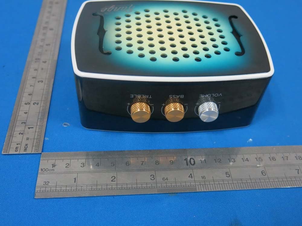
PXK-HL2515
Dec 22, 2014Strum
Equipment Class
DTS - Digital Transmission System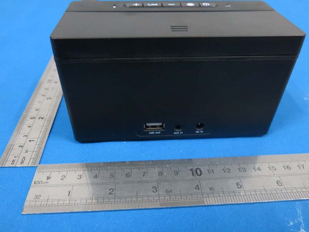
PXK-HL2507
Dec 22, 2014Express Speaker
Equipment Class
DTS - Digital Transmission System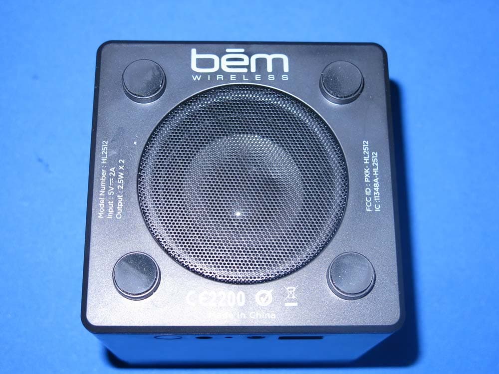
PXK-HL2512
Dec 22, 2014Eclipse
Equipment Class
DSS - Part 15 Spread Spectrum Transmitter
PXK-HT1051
Sep 09, 2014Magic SoundBox Bluetooth speaker
Equipment Class
DSS - Part 15 Spread Spectrum Transmitter