PZ3-FM72Part 90.238 Telemetry Transmitter
Primex Wireless, Inc.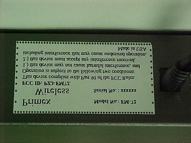
Click to zoom
Application Details
- Equipment Class
- TNB - Licensed Non-Broadcast Station Transmitter
- Date of Grant
- Dec 13, 2001
- Application Purpose
- Original Equipment
- Date of Application
- Dec 10, 2001
- Equipment Note
- Part 90.238 Telemetry Transmitter
- Frequency Range
- 72.10000000 - 72.40000000
- Company
- Primex Wireless, Inc.
- Country
- United States
Documents & Files
Document Text
Text extracted from the exhibit documents filed with the FCC. Open a document above to read the original.
Cover Letter(s)
FCC ID: PZ3-FM72 Response to TCB findings Hi Jim, We have identified these issues following our review: 1. Please provide substitution measurements of spurious radiated emissions. While direct conversion of electric field measurements has been acceptable in the past, over the past two years the FCC has required substitution measurements as described in ANSI/TIA/EIA-603-1992 section 2.2.12 for all licensed services. Response – Following is a brief response to item #1 in the e-mail from Barry Quinlan, as he has requested: Upon reviewing the radiated spurious emission data from the radiated emission report, we at L.S. Compliance feel confident that a remeasurement of the spurious radiation components using the substitution method may not actually be necessary. This is due to the large margin (~50DB) by which the previously measured emissions was found to be below the nominal -13 dBm limit. (equiv F.S. of 82 dB/uV/m in the three meter chamber.) We are happy to provide the data using the substitution method if need be, but feel that in this particular case, the remeasurement may not be necessary. Also, in the addendum to TIA/EIA-603, section 2.2.12 has additional language that states; "The magnitude of emissions attenuated more than 20 dB below the FCC limit need not be recorded" 2. Please provide an exhibit showing the DC currents and voltages supplied to the final amplifier stage. See 2.1033(c)(8). Response – see revised test report 3. Please provide the factory tune up procedure (if one is used). See 2.1033(c)(9). Response – see tune up procedure 4. Please provide frequency stability measurements with respect to input voltage changes per 2.1055(d). Response – see revised test report Best regards Barry C. Quinlan Certification & Telecom Manager ------------------------------------------------------------------------------- Curtis-Straus LLC Voice: 978.486.8880 x270 527 Great Road Fax: 978.486.8828 Littleton, MA 01460 http://www.curtis-straus.com --------------------------------------------------------------------------------
Cover Letter(s)
November 8, 2001 FEDERAL COMMUNICATIONS COMMISSION 7435 Oakland Mills Road Columbia, MD 21046 Subject: Request for Non disclosure for FCC ID: PZ3-FM72. To Whom It May Concern: Pursuant to 47 CFR Section 0.459, Primex, Inc. hereby requests non disclosure and confidential treatment of the following materials submitted in support of FCC certification application for FCC ID # PZ3-FM72. a. Schematic Diagrams b. Operational Description c. Block Diagram Above materials contain trade secrets, proprietary and technical information which would customarily be guarded from competitors under 47 CFR section 0.457(d)(2). Disclosure or publication of any portion of this company confidential material to other parties could cause substantial competitive harm and provide unjustified benefits for competitors. Primex, Inc. understands that pursuant to 47 CFR section 0.457(d)(1)(ii) disclosure of the applicant and all accompanying documentation will not be made before the date of the grant. Sincerely yours, Darrel Thompson President Primex, Inc.
External Photos
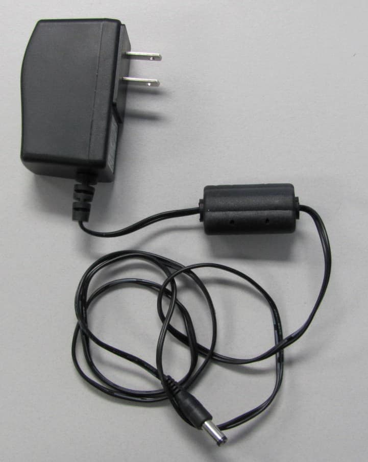
Primex, Inc. ( Quartex USA ) Primex Wireless Master Lock FCC ID#: PZ3-FM72 Photo One Front Cover with Antenna and Power Cord connected. LCD Display’s Current Clock Time Primex, Inc. ( Quartex USA ) Primex Wireless Master Lock FCC ID#: PZ3-FM72 Photo Two Close-up of Antenna Connection Primex, Inc. ( Quartex USA ) Primex Wireless Master Lock FCC ID#: PZ3-FM72 Photo Four Back Panel close-up showing ... FCC ID Label, Power Connection, DIP Programming Switch and I/O Connections Primex, Inc. ( Quartex USA ) Primex Wireless Master Lock FCC ID#: PZ3-FM72 Photo Three Back Panel showing ... FCC ID Label, Power Connection, DIP Programming Switch and I/O Connections Primex, Inc. ( Quartex USA ) Primex Wireless Master Lock FCC ID#: PZ3-FM72 Photo Five FCC ID Label Close-Up
ID Label/Location Info
Sample FCC Label: *************************************************** * Primex Model No.: FM-72 * * Wireless Serial No. : xxxxxx * * FCC ID: PZ3-FM72. * * This device complies with Part 90 of the FCC Rules. * * Operation is subject to the following two conditions: * * 1.) this device may not cause harmful interference, and * * 2.) this device must accept any interference received, * * including interference that may cause undesired operation. * * Made in USA * *************************************************** FCC label material for ... Primex Wireless FM-72 Face Stock: Material : Clear Polyester Thickness : .025+/-.002mm Specific Weight: 33.2 gram/M^2 Color : Clear Glue: Material Acrylic compound Glue Thickness ; .02+/-.002 mm Volume of the glue applied: 28 +/-.002 gram/mm^2 Adhesion Force: 8+/-.56 kgs/25mm^2 Working Temp: -10 C to 105 C
Internal Photos
Primex, Inc. ( Quartex USA ) Primex Wireless Master Lock FCC ID#: PZ3-FM72 Photo Six Open for Inspection Primex, Inc. ( Quartex USA ) Primex Wireless Master Lock FCC ID#: PZ3-FM72 Photo Seven Single PCB showing Non-Component Side with Antenna Connections Primex, Inc. ( Quartex USA ) Primex Wireless Master Lock FCC ID#: PZ3-FM72 Photo Eight Single PCB showing Component Side with RF Section Shielded Primex, Inc. ( Quartex USA ) Primex Wireless Master Lock FCC ID#: PZ3-FM72 Photo Nine Single PCB showing Antenna Connection
Parts List/Tune Up Info
L.S. RESEARCH Inc. HIGH TECHNOLOGY ELECTRONIC CONSULTANTS File:TCB Question 3 Production TX Procedure.doc CONFIDENTIAL Page 1 of 4 Synchronized Clock Transmitter and Receiver Question 3 Test and Alignment Procedure V1.0 prepared for Quartex, Division of Primex, Inc. L.S. RESEARCH Inc. HIGH TECHNOLOGY ELECTRONIC CONSULTANTS File:TCB Question 3 Production TX Procedure.doc CONFIDENTIAL Page 2 of 4 Equipment List: 1. DVM (Remote Controlled for automation) 2. Power supply 3V @ 35mA 3. Power supply 9V @ 350mA 4. Agilent Arbitrary Waveform Generator 33250A or 33120A 5. HP8920B with the following options: 001 high stability time base 007 low Level Power measurements 102 spectrum analyzer with tracking generator L.S. RESEARCH Inc. HIGH TECHNOLOGY ELECTRONIC CONSULTANTS File:TCB Question 3 Production TX Procedure.doc CONFIDENTIAL Page 3 of 4 Quartex Synchronized Clock Transmitter Production Test and Alignment Procedure 1. LCD Display Contrast Adjustment A. Apply 9VDC to the transmitter board via the power jack. B. Adjust VR1 for good display contrast OR measure the resistance from pin 3 on J5 and adjust VR1 for a reading of 985 Ohms. C. Activate the GPS simulator and verify communication with the transmitter. 2. Deviation, Frequency Stablilty, and Output Power. A. Set up the HP8920B in the following way, either remotely or from the front panel. a. Go to the AF analyzer screen and set the AF anl in to FM Demod. b. Set the Detector to Pk+-/2. c. Go back to the RF analyzer screen. d. Set the power units to dBm B. Set up the Transmitter board in the following way: a. Switch the transmitter to Channel 8 (position 7 on the rotary switch S1). b. Apply 9 VDC to the board via the power jack. c. Activate the GPS simulator on the GPS 9 pin connector. d. Connect the Transmitter J1 to the HP8920B. I. Peak Frequency Deviation Test A. Read Peak Frequency deviation B. PASS if greater than 2.5kHz and less than 3.2kHz II. Transmitter Frequency Test A. Read the Frequency in MHz B. PASS if frequency is 72.24MHz +/- 250Hz III. Power Output Test A. Read the Power in dBm B. Calculate actual power in dBm = Power read + cable losses C. PASS if actual power in dBm is less than 29.5dBm and greater than 26.9dBm L.S. RESEARCH Inc. HIGH TECHNOLOGY ELECTRONIC CONSULTANTS File:TCB Question 3 Production TX Procedure.doc CONFIDENTIAL Page 4 of 4 3. Second Harmonic Level Test (leave the Transmitter board set up as in step 2). A. Measure level of the fundamental (Menu and screens apply to the HP8920B) a. Go to Spectrum Analyzer screen b. Set Center Freq=72.24MHz, Ref Level=30dBm, Span=0.1MHz c. Set Controls to Auxiliary, and to Peak Hold. Allow 5 seconds to peak hold. d. Set Controls to Marker, and Marker to Peak. e. Record the level. B Measure the level of the Second Harmonic(Menu and screens apply to the HP8920B) a. Go to Spectrum Analyzer screen b. Set Center Freq=144.48MHz, Ref Level=30dBm, Span=0.1MHz c. Set Controls to Auxiliary, and to Peak Hold. Allow 5 seconds to peak hold. d. Set Controls to Marker, and Marker to Peak. e. Record the level. C. Calculate the difference a. The level taken in step A – the level taken in step B b. PASS if the difference is greater than 43dB. 5. Check Tuning Voltage (leave the Transmitter board set up as in step 2). A. Probe TP1 TUNING with a DVM and measure the voltage B. PASS if the voltage is greater than 0.5Volts and less than 4.5Volts 6. Measure Transmitter Current Drain (leave the Transmitter board set up as in step 2). A. Measure the current draw from the 9 Volt Supply with a DVM B. PASS if the current measured is greater than 280mA and less than 350mA at 9Volts 4. 20 MHz Clock Oscillator Alignment A. Remove power from the Transmitter board. B. Deactivate the GPS simulator to stop the board from transmitting. C. Reapply the 9 VDC supply to the Transmitter board. B. Bring High impedance “sniffer probe” connected to an RF Frequency counter close to the 20 MHz crystal oscillator. C. Adjust VC1 with a ceramic tuning tool for a frequency of 20MHz +/- 100Hz
RF Exposure Info
FCC ID: PZ3-FM72 MAXIMUM PERMISSIBLE EXPOSURE CALCULATIONS The effective radiated power for this device is based on the worst case conducted power output, and the specified gain of the quaarter wave whip mounted on the outside of the case. The measured power output of the equipment is measured at 27.5 dBm, and the antenna gain, referenced to isotropic, is 0.5 dBi. The effective radiated power at the antenna aperture is; Pt = 27.5 dBm + 0.5 dB = 28.0 dBm or in watts; 10**(28.0/10) = 0.631 watts The expected power density at a 20 centimeter distance is: W(r) = P.O. / 4 (pi) R** 0.631 / 12.56 x 0.2** 0.631 / 0.5024 = 1.256w/m** Re-normalizing this power density to square centimeter: W(r) = 1.256 w/m**)/10,000 = 0.1256 mW/cm** The limit for M.P.E. given in Table 1 (b) of 1.1310, for the frequency range 30-300 MHz is: 0.2 mW/cm** And: 0.1256 mW/cm** < 0.2 mW/cm** So the device meets the MPE requirement.
Test Report
.......... . . . . . . . . . . L.S. Research Inc. Quartex Synchronization Transmitter Appendix “A” to L. S. Compliance, Inc. Report Number 301190T Part 90 Type Acceptance, Conducted Measurements prepared for Quartex, Division of Primex, Inc. L.S. Research Inc. W66 N220 Commerce Court Cedarburg, WI 53012 Phone 262.375.4400 Fax 262.375.4248 Revision 1.0 L.S. RESEARCH Inc. 2 HIGH TECHNOLOGY ELECTRONIC CONSULTANTS Confidential WE HAVE DESIGNS ON THE FUTURE W66 N220 Commerce Court, Cedarburg, Wisconsin 53012 • 414-375-4400 • FAX 414-375-4248 Email: [email protected] www.lsr.com Table of Contents I. PROJECT INFORMATION...................................................................................................................................3 II. FCC CONDUCTED TESTS...................................................................................................................................5 A. PART 90 SUBPART I..................................................................................................................................................5 1. 90.207 (a) (1) Types of Emmisions (Device Classification)........................................................................5 2. 90.209 (a) (5) Bandwidth Limitations (Device Classification, Test Condition)......................................5 3. Part 2.1046 Output Power, Part 2.1051 Spurious Emissions at Antenna terminals and Part 2.1049 Occupied bandwidth using 90.210 (c) Emission Mask for F1D Transmitter....................................................6 4. Part 2.1055 and 90.213 (a) and (d) Frequency Stability.........................................................................12 III. EQUIPMENT LIST...........................................................................................................................................14 IV. EQUIPMENT UNCERTAINTIES...................................................................................................................14 V. UNCERTAINTY ANALYSIS................................................................................................................................15 L.S. RESEARCH Inc. 3 HIGH TECHNOLOGY ELECTRONIC CONSULTANTS Confidential WE HAVE DESIGNS ON THE FUTURE W66 N220 Commerce Court, Cedarburg, Wisconsin 53012 • 414-375-4400 • FAX 414-375-4248 Email: [email protected] www.lsr.com Surveillance Transmitter I. Project Information Project: Surveillance Transmitter Quartex Contact: Company: Quartex Full Name: Mike Pikula Job Title: Electronic Project Engineer 1012 Host Drive Lake Geneva, WI 53147 Bus: (262) 248-1540 Bus Fax: (262) 248-3666 E-mail: [email protected] L.S. RESEARCH Inc. 4 HIGH TECHNOLOGY ELECTRONIC CONSULTANTS Confidential WE HAVE DESIGNS ON THE FUTURE W66 N220 Commerce Court, Cedarburg, Wisconsin 53012 • 414-375-4400 • FAX 414-375-4248 Email: [email protected] www.lsr.com LS Research Contact: Bill Steinike, Operations Manager Mike Jonely, Test Engineer Brian Petted, Vice President of Engineering Voice: 414-375-4400 Fax: 414-375-4248 Email: [email protected] Proposal Date: Revision: Proposal #: Proposal File: Job Number: Signatures: Technical Approval Brian Petted, MS Vice-President of Engineering L.S. RESEARCH Inc. 5 HIGH TECHNOLOGY ELECTRONIC CONSULTANTS Confidential WE HAVE DESIGNS ON THE FUTURE W66 N220 Commerce Court, Cedarburg, Wisconsin 53012 • 414-375-4400 • FAX 414-375-4248 Email: [email protected] www.lsr.com II. FCC Conducted Tests A. Part 90 Subpart I 1. 90.207 (a) (1) Types of Emissions (Device Classification) Classified as an F1D emitter (Frequency Modulation, Digital Modulation, Data). Power level: 1W. 2. 90.209 (a) (5) Bandwidth Limitations (Device Classification, Test Condition). 20 kHz Nominal Channel Bandwidth L.S. RESEARCH Inc. 6 HIGH TECHNOLOGY ELECTRONIC CONSULTANTS Confidential WE HAVE DESIGNS ON THE FUTURE W66 N220 Commerce Court, Cedarburg, Wisconsin 53012 • 414-375-4400 • FAX 414-375-4248 Email: [email protected] www.lsr.com 3. Part 2.1046 Output Power, Part 2.1051 Spurious Emissions at Antenna terminals and Part 2.1049 Occupied bandwidth using 90.210 (c) Emission Mask for F1D Transmitter. a) Test Requirement: (1) On any frequency removed from the center of the authorized bandwidth by a displacement frequency (f d in kHz) of more than 5kHz but not more than 10kHz: At least 83 log (f d/5) dB. (2) On any frequency removed from the center of the authorized bandwidth by a displacement frequency (f d in kHz) of more than 10 kHz but no more than 250 percent of the authorized bandwidth: At least 29 log (f d 2 /11) dB or 50 dB, whichever is the lesser attenuation. (3) On any frequency removed from the center of the authorized bandwidth by more than 250 percent of the authorized bandwidth: At least 43 + 10 log (P) dB. P is output power in Watts. The test condition is presented in Tabular form below. The definition of the spectrum mask as indicated on the spectrum analyzer is also presented. 90.210 (c) Absolute Frequency Offset Range: |f d | Attenuation relative to Carrier power P. (1) 0 to 5 kHz 0 dB (1) 5 kHz to 10 kHz 83 log (f d/5) dB (2) 10 kHz to 70 kHz 29 log (f d 2 /11) dB or 50 dB, whichever is the lesser attenuation. (3) Greater than 70 kHz 43 + 10 log (P) dB L.S. RESEARCH Inc. 7 HIGH TECHNOLOGY ELECTRONIC CONSULTANTS Confidential WE HAVE DESIGNS ON THE FUTURE W66 N220 Commerce Court, Cedarburg, Wisconsin 53012 • 414-375-4400 • FAX 414-375-4248 Email: [email protected] www.lsr.com 16:12:06 Oct 29, 2001 A:\LIMIT125.LIM file saved Select Marker 1234 Normal Delta Band Pair S tartStop Span Pair SpanCenter Off More 1 of 2 Marker Ref -10 dBm#Atten 0 dB Peak Log 10 dB/ W1S2 S3FC AA Center 72.24 MHz Res BW 300 HzVBW 300 Hz Span 50 kHz Sweep 2.226 s (401 pts) b) Test Configuration PC HP E4402B Equipment Under Test (Transmitter) Equipment Under Test Configuration Data Capture RF Output L.S. RESEARCH Inc. 8 HIGH TECHNOLOGY ELECTRONIC CONSULTANTS Confidential WE HAVE DESIGNS ON THE FUTURE W66 N220 Commerce Court, Cedarburg, Wisconsin 53012 • 414-3…
Text truncated - open the document above for the full version.
Test Report
L.S. Compliance, Inc. W66 N220 Commerce Court Cedarburg, WI 53012 262-375-4400 _____________________________________________________________________________ COMPLIANCE TESTING OF: Quartex Synchronization Transmitter Model FM-72 PREPARED FOR: Quartex, Division of Primex, Inc. 965 Wells Street Lake Geneva, WI 53147 TEST REPORT NUMBER: 301190 T DATE(S) OF TESTING: October 19 th and 30 th , 2001 All results of this report relate only to the items that were tested. This report is not to be reproduced, except in full, without written approval of L. S. Compliance, Inc. L.S. Compliance, Inc. Page 2 of 22 Test Report Number: 301190 T Prepared For: Quartex Table of Contents Section Description Test Type Page Index 2 1 L. S. Compliance in Review 3 2 A2LA Certificate of Accreditation 4 3 A2LA Scope of Accreditation 5 4 Validation Letter-U.S. Competent Body for EMC Directive 89/336/EEC 6 5 Signature Page 7 6 Product and General Information 8 7 Product Description 8 8 Test Requirements 8 9 Summary of Test Report 9 10 Introduction 9 11 Purpose 9 12 Radiated Emissions Test, enclosure FCC 10-15 13 Conducted Emission Test, AC line FCC 16-20 14 Test Equipment List 21 Appendix A Part 90 Type Acceptance, Conducted Measurements 22 L.S. Compliance, Inc. Page 3 of 22 Test Report Number: 301190 T Prepared For: Quartex 1. L. S. Compliance In Review L. S. Compliance, Inc. is located in Cedarburg, Wisconsin – United States. We may be contacted by: Mail: L. S. Compliance, Inc. W66 N220 Commerce Court Cedarburg, Wisconsin 53012 Phone: 262-375-4400 Fax: 262-375-4248 E-mail: [email protected] As an EMC Testing Laboratory, our Accreditation and Assessments are recognized through the following: A2LA – American Association for Laboratory Accreditation Accreditation based on ISO/IEC 17025 : 1999 with Electrical (EMC) Scope of Accreditation A2LA Certificate Number: 1255.01 U. S. Conformity Assessment Body (CAB) Validation Validated by the European Commission as a U. S. Conformity Assessment Body operating under the U. S. /EU, Mutual Recognition Agreement (MRA) operating under the European Union EMC Directive 89/336/EEC, Article 10.2. Date of Validation: January 16, 2001 Federal Communications Commission (FCC) – USA Listing of 3 Meter Semi-Anechoic Chamber based on 47CFR 2.948 FCC Registration Number: 90756 Listing of 3 and 10 meter OATS based on 47CFR 2.948 FCC Registration Number: 90757 Industry Canada On-file, 3 Meter Semi-Anechoic Chamber based on 47CRF 2.948 File Number: IC 3088 On-file 3 and 10 Meter OATS based on RSS-210 File Number: IC 3088-A L.S. Compliance, Inc. Page 4 of 22 Test Report Number: 301190 T Prepared For: Quartex 2. A2LA Certificate of Accreditation L.S. Compliance, Inc. Page 5 of 22 Test Report Number: 301190 T Prepared For: Quartex 3. A2LA Scope of Accreditation L.S. Compliance, Inc. Page 6 of 22 Test Report Number: 301190 T Prepared For: Quartex 4. Validation Letter – U.S. Competent Body for EMC Directive 89/336/EEC L.S. Compliance, Inc. Page 7 of 22 Test Report Number: 301190 T Prepared For: Quartex 5. Signature Page Prepared By: November 9, 2001 Teresa A. White, Document Coordinator Date Tested By: November 9, 2001 Kenneth L. Boston, EMC Lab Manager Date Tested By: November 9, 2001 Thomas T. Lee, EMC Engineer Date NARTE Test Lab Engineer, ALT-0064-E Approved By: November 9, 2001 Kenneth L. Boston, EMC Lab Manager Date PE#31926 Licensed Professional Engineer Registered in the State of Wisconsin, United States L.S. Compliance, Inc. Page 8 of 22 Test Report Number: 301190 T Prepared For: Quartex 6. Product and General Information Manufacturer: Quartex, Division of Primex, Inc. Model No.: FM-72 Serial No.: Pre-production Description: Data Transmitter Frequency Range: 72.0 – 73.0 MHz 7. Product Description The FM-72 is a data transmitter, which sends telemetry to various co-located paging receivers, which are located in wall clocks, for the purpose of time synchronization. It is provided for by 47 CFR, Part 90.238 as a telemetry device. 8. Test Requirements The following FCC requirements are met: 47 CFR, 2.1053, 90.257(b)(2), 90.210. L.S. Compliance, Inc. Page 9 of 22 Test Report Number: 301190 T Prepared For: Quartex 9. Summary of Test Report DECLARATION OF CONFORMITY The Equipment Under Test (EUT) was found to MEET the requirements as described within the specification of Title 47 CFR FCC, Part 90, Subpart J, and Part 2.1053 Radiated Spurious Emissions for a low-power non-broadcast transmitter. 10. Introduction On October 19, 2001 a series of Radiated Emission tests were performed on the EUT. These tests were performed using the procedures outlined in ANSI C63.4-2001 for unintentional radiators, and in accordance with the limits set forth in FCC Part 90 for a non-voice and other specialized operation transmitters. These tests were performed by Kenneth Boston, EMC Lab Manager and Thomas T. Lee, EMC Engineer/NARTE Test Lab Engineer of L.S. Compliance. 11. Purpose All Radiated Emission tests upon the EUT were performed to measure the emissions in the frequency bands described in title 47 CFR, FCC Part 90, including 90.210 (general technical parts) to determine whether these emissions are below the limits expressed within the standards. AC line Conducted Emissions were also measured and compared to the CFR, Part 15.207 limits, as additional technical data. These tests were performed in accordance with the procedure described in the American National Standard for methods of measurement of Radio-Noise Emissions from Low-Voltage Electrical and Electronic Equipment in the Range of 9 kHz to 40 GHz (ANSI C63.4-2001). Another document used as a reference for the EMI Receiver specification was the Comite International Special Des Perturbations Radioelelectriques (CISPR) Number 16-1, 1993. L.S. Compliance, Inc. Page 10 of 22 Test Report Number: 301190 T Prepared For: Quartex 12. Radiated Emissions Test Test Setup The test setup was assembled in accordance with ANSI C63.4-2001. The Quartex FM-72 was placed on an 80cm hig…
Text truncated - open the document above for the full version.
Test Report
.......... . . . . . . . . . . LS Research Inc. Quartex Synchronization Transmitter Question 2 and 4 Part 90 Type Acceptance, Conducted Measurements V1.1 prepared for Quartex, Division of Primex, Inc. L.S. Research Inc. W66 N220 Commerce Court Cedarburg, WI 53012 Phone 414.375.4400 Fax 414.375.4248 Revision 1.0 L.S. RESEARCH Inc. 2 HIGH TECHNOLOGY ELECTRONIC CONSULTANTS Confidential WE HAVE DESIGNS ON THE FUTURE W66 N220 Commerce Court, Cedarburg, Wisconsin 53012 • 414-375-4400 • FAX 414-375-4248 Email: [email protected] www.lsr.com Table of Contents I. PROJECT INFORMATION..............................................................................................................................3 II. FCC CONDUCTED TESTS..............................................................................................................................5 A. P ART 90 SUBPART I ............................................................................................................................................5 1. 90.207 (a) (1) Types of Emmisions (Device Classification) .........................................................................5 2. 90.209 (a) (5) Bandwidth Limitations (Device Classification, Test Condition). .........................................5 3. Part 2.1046 Output Power, Part 2.1051 Spurious Emissions at Antenna terminals and Part 2.1049 Occupied bandwidth using 90.210 (c) Emission Mask for F1D Transmitter. .......................................................6 4. Part 2.1055 and 90.213 (a) and (d) Frequency Stability.............................................................................12 5. Part2.1033(c)(8) DC currents and voltages supplied to the finalamplifier stage......................................15 III. EQUIPMENT LIST ......................................................................................................................................16 IV. EQUIPMENT UNCERTAINTIES ..............................................................................................................16 V. UNCERTAINTY ANALYSIS ..........................................................................................................................17 L.S. RESEARCH Inc. 3 HIGH TECHNOLOGY ELECTRONIC CONSULTANTS Confidential WE HAVE DESIGNS ON THE FUTURE W66 N220 Commerce Court, Cedarburg, Wisconsin 53012 • 414-375-4400 • FAX 414-375-4248 Email: [email protected] www.lsr.com Surveillance Transmitter I. Project Information Project: Surveillance Transmitter Quartex Contact: Company: Quartex Full Name: Mike Pikula Job Title: Electronic Project Engineer 1012 Host Drive Lake Geneva, WI 53147 Bus: (262) 248-1540 Bus Fax: (262) 248-3666 E-mail: [email protected] L.S. RESEARCH Inc. 4 HIGH TECHNOLOGY ELECTRONIC CONSULTANTS Confidential WE HAVE DESIGNS ON THE FUTURE W66 N220 Commerce Court, Cedarburg, Wisconsin 53012 • 414-375-4400 • FAX 414-375-4248 Email: [email protected] www.lsr.com LS Research Contact: Bill Steinike, Operations Manager Mike Jonely, Test Engineer Brian Petted, Vice President of Engineering Voice: 414-375-4400 Fax: 414-375-4248 Email: [email protected] Proposal Date: Revision: Proposal #: Proposal File: Job Number: Signatures: Technical Approval L.S. RESEARCH Inc. 5 HIGH TECHNOLOGY ELECTRONIC CONSULTANTS Confidential WE HAVE DESIGNS ON THE FUTURE W66 N220 Commerce Court, Cedarburg, Wisconsin 53012 • 414-375-4400 • FAX 414-375-4248 Email: [email protected] www.lsr.com II. FCC Conducted Tests A. Part 90 Subpart I 1. 90.207 (a) (1) Types of Emissions (Device Classification) Classified as an F1D emitter (Frequency Modulation, Digital Modulation, Data). Power level: 1W. 2. 90.209 (a) (5) Bandwidth Limitations (Device Classification, Test Condition). 20 kHz Nominal Channel Bandwidth L.S. RESEARCH Inc. 6 HIGH TECHNOLOGY ELECTRONIC CONSULTANTS Confidential WE HAVE DESIGNS ON THE FUTURE W66 N220 Commerce Court, Cedarburg, Wisconsin 53012 • 414-375-4400 • FAX 414-375-4248 Email: [email protected] www.lsr.com 3. Part 2.1046 Output Power, Part 2.1051 Spurious Emissions at Antenna terminals and Part 2.1049 Occupied bandwidth using 90.210 (c) Emission Mask for F1D Transmitter. a) Test Requirement: ( 1) On any frequency removed from the center of the authorized bandwidth by a displacement frequency (f d in kHz) of more than 5kHz but not more than 10kHz: At least 83 log (f d/5) dB. (2) On any frequency removed from the center of the authorized bandwidth by a displacement frequency (f d in kHz) of more than 10 kHz but no more than 250 percent of the authorized bandwidth: At least 29 log (f d 2 /11) dB or 50 dB, whichever is the lesser attenuation. (3) On any frequency removed from the center of the authorized bandwidth by more than 250 percent of the authorized bandwidth: At least 43 + 10 log (P) dB. P is output power in Watts. The test condition is presented in Tabular form below. The definition of the spectrum mask as indicated on the spectrum analyzer is also presented. 90.210 (c) Absolute Frequency Offset Range: |f d | Attenuation relative to Carrier power P. (1) 0 to 5 kHz 0 dB (1) 5 kHz to 10 kHz 83 log (f d/5) dB (2) 10 kHz to 70 kHz 29 log (f d 2 /11) dB or 50 dB, whichever is the lesser attenuation. (3) Greater than 70 kHz 43 + 10 log (P) dB L.S. RESEARCH Inc. 7 HIGH TECHNOLOGY ELECTRONIC CONSULTANTS Confidential WE HAVE DESIGNS ON THE FUTURE W66 N220 Commerce Court, Cedarburg, Wisconsin 53012 • 414-375-4400 • FAX 414-375-4248 Email: [email protected] www.lsr.com 16:12:06 Oct 29, 2001 A:\LIMIT125.LIM file saved Select Marker 1234 Normal Delta Band Pair StartStop Span Pair SpanCenter Off More 1 of 2 Marker Ref -10 dBm#Atten 0 dB Peak Log 10 dB/ W1 S2 S3 FC AA Center 72.24 MHz Res BW 300 HzVBW 300 Hz Span 50 kHz Sweep 2.226 s (401 pts) b) Test Configuration PC HP E4402B Equipment Under Test (Transmitter) Equipment Under Test Configuration Data Capture RF Output L.S. RESEARCH Inc. 8 HIGH TECHNOLOGY ELECTRONIC CONSULTANTS Confidential WE HAVE DESIGNS ON THE FUTURE W66 N220 Commerce Court, Cedarburg…
Text truncated - open the document above for the full version.
Test Setup Photos
L.S. Compliance, Inc. Page 14 of 22 Test Report Number: 301190 T Prepared For: Quartex Photos Taken During Radiated Emissions Testing Test Setup for Radiated Emissions Testing in the 3 Meter Chamber View of the EUT during the Radiated Emissions Testing. Antenna in place, but port internally terminated with a 50 Ohm load.
Contact Information
Applicant
Arthur John Mahanna(Product Manager)
Test Firm
LS Research, LLCRyan Urness
Technical Specifications
| # | Rule Parts | Frequency Range | Power Output | Emission | Tolerance |
|---|---|---|---|---|---|
| 1 | 90 | 72.1 MHz - 72.4 MHz | 1 W | 20K0F1D | 2.4000000000 ppm |
Other Applications from Primex Wireless, Inc.
PZ3-SNSH
Nov 09, 2011Synchronous Network System AC Temperature & Humidity Sensor
Equipment Class
DTS - Digital Transmission System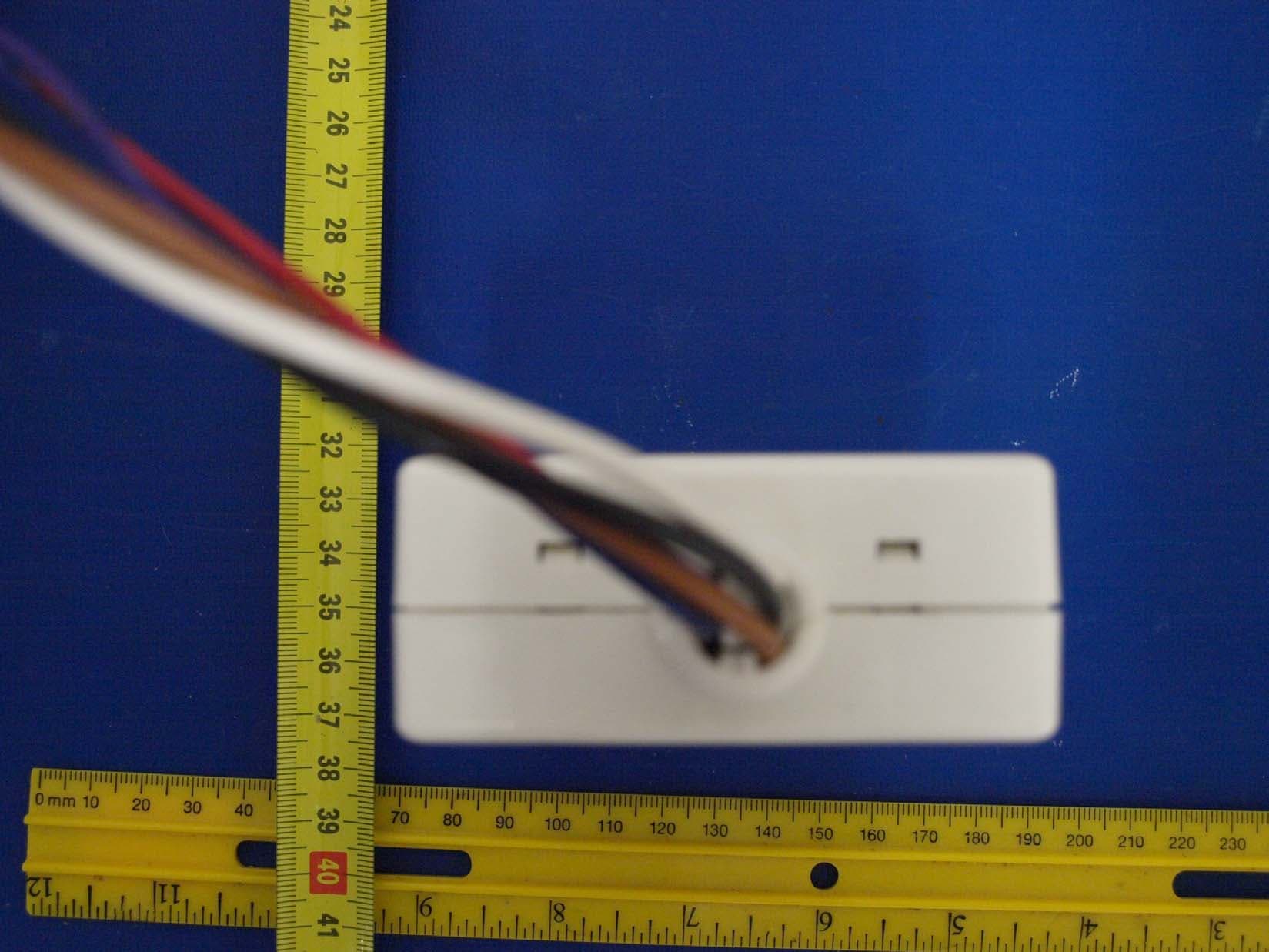
PZ3-SNSE
Mar 15, 2011Emergency Lighting Controller
Equipment Class
DSS - Part 15 Spread Spectrum Transmitter
PZ3-SNSP
Oct 19, 2010Synchronous Network System Personal Series Clock
Equipment Class
DTS - Digital Transmission System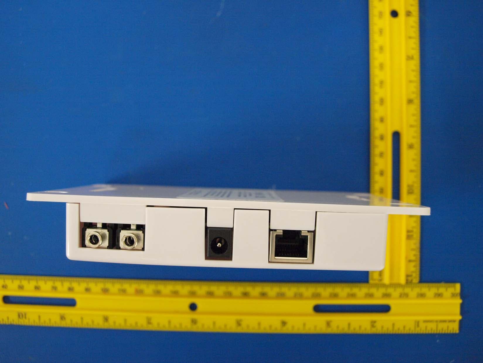
PZ3-SNST
May 03, 2010SYNCHRONOUS NETWORK SYSTEM TEMPERATURE SENSOR
Equipment Class
DTS - Digital Transmission System
PZ3-SNSA
Apr 14, 2008Synchronous Network Analog Clocks
Equipment Class
DTS - Digital Transmission System