PZ3-SNSHSynchronous Network System AC Temperature & Humidity Sensor
Primex Wireless, Inc.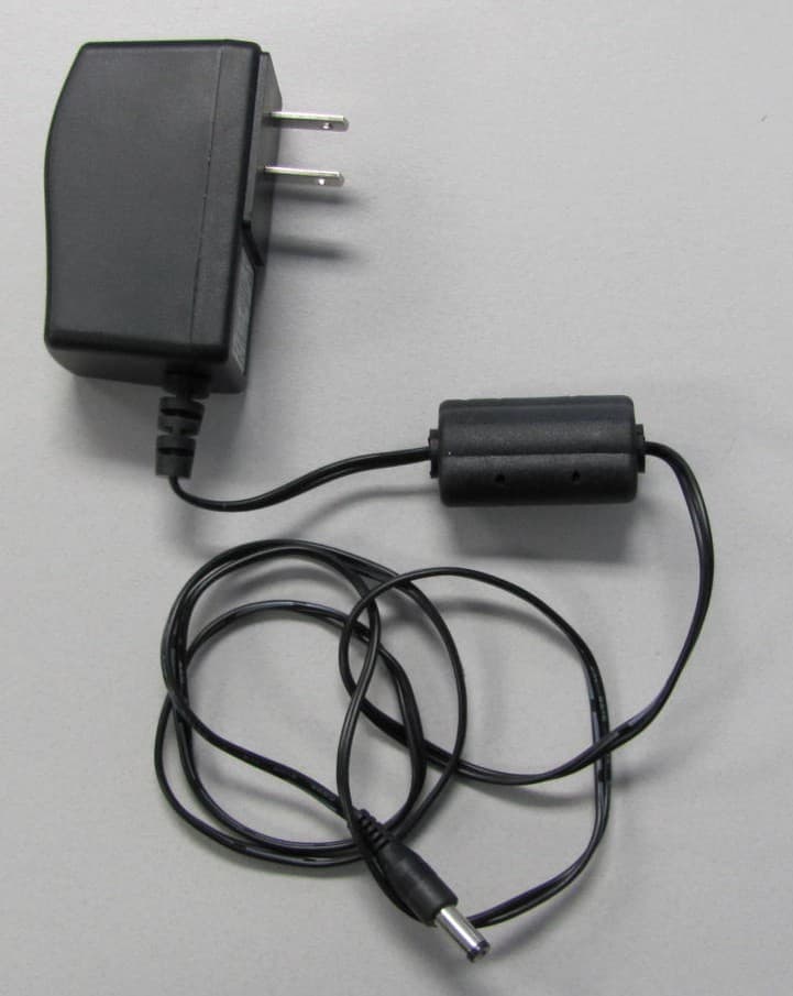
Click to zoom
Application Details
- Equipment Class
- DTS - Digital Transmission System
- Date of Grant
- Nov 09, 2011
- Application Purpose
- Original Equipment
- Date of Application
- Nov 09, 2011
- Equipment Note
- Synchronous Network System AC Temperature & Humidity Sensor
- Frequency Range
- 2412.00000000 - 2462.00000000
- Company
- Primex Wireless, Inc.
- Country
- United States
Documents & Files
Document Text
Text extracted from the exhibit documents filed with the FCC. Open a document above to read the original.
Users Manual
SNS™ Temperature and Humidity Sensors Installation Guide Document Part No.: SNSDOC-012 10/17/2011 Primex Wireless, Inc. SNS™ Temperature and Humidity Sensors Installation Guide 2 SNS™ Temperature and Humidity Sensors Installation Guide Product Models US: SNS2TPS-2, SNS2TPD-2, SNS2TNS-2, SNS2THS-2, SNSATPS, SNSATPD, SNSATHX UK: SNS2TPS-2, SNS2TPD-2, SNS2TNS-2, SNS2THS-2, SNSGTPS, SNSGTPD, SNSGTHX EU: SNS2TPS-2, SNS2TPD-2, SNS2TNS-2, SNS2THS-2, SNSCTPS, SNSCTPD, SNSCTHX Legal Notice Copyright ©2011 Primex Wireless, Inc. All rights reserved. SNS is a trademark of Primex Wireless, Inc. U.S. Patents 6,873,573; 7,352,657. Other Patents Pending. Printed in the USA. Reference Documentation Note: Reference documentation is located on the SNS Resource CD (Q13140) and in the Support area of the SNS AMP software. SNS™ Temperature and Humidity Sensors User Guide (SNSDOC-006) SNS™ AMP Installation and Administration Guide (SNSDOC-005) Contact Primex Wireless Web: http://www.primexwireless.com/ E-mail: [email protected] United States Canada United Kingdom Telephone (800) 404-8112 (800) 404-8112 0800-3896996 Hours 7:00am - 5:00pm Central 7:00am - 5:00pm Central 8:30am – 5:00pm GMT Fax (262) 248-0061 (905) 952-0134 01422-349462 Primex Wireless, Inc. SNS™ Temperature and Humidity Sensors Installation Guide 3 Contents Safety Precautions .............................................................................................................................. 5 Safety Precautions ............................................................................................................................. 5 Equipment Precautions ...................................................................................................................... 5 About this Guide .................................................................................................................................. 6 Documentation Overview ................................................................................................................... 6 Guide Conventions ............................................................................................................................. 6 Introducing SNS™ Temperature and Humidity Sensors................................................................... 7 Sensor Devices and Accessories ....................................................................................................... 7 Overview of SNS Sensor Network Installation .................................................................................... 9 Network Requirements for SNS Sensor Devices ............................................................................. 11 Wireless Signal ................................................................................................................................ 11 Wireless Security.............................................................................................................................. 11 Network Protocol and Ports .............................................................................................................. 11 Features of SNS AC-powered Sensor Devices ................................................................................ 12 Network, Power, and Probe Connections ......................................................................................... 12 Service Button .................................................................................................................................. 12 Visual and Auditory Interfaces .......................................................................................................... 13 Monitoring Thresholds ...................................................................................................................... 15 Operational Sequences .................................................................................................................... 15 Features of SNS Battery-powered Sensor Devices ......................................................................... 18 On/Off Switch ................................................................................................................................... 18 Batteries ........................................................................................................................................... 19 Programming Cable Connection ....................................................................................................... 19 Probe Connections ........................................................................................................................... 20 Service Button .................................................................................................................................. 20 Visual and Auditory Interfaces .......................................................................................................... 21 Monitoring Thresholds ...................................................................................................................... 22 Operational Sequences .................................................................................................................... 23 Configure Sensors for the Network .................................................................................................. 25 Select the Configuration Method ...................................................................................................... 25 Edit Default Sensor Profiles .............................................................................................................. 25 Configure AC-powered Sensors using Discovery and Auto-Configuration ........................................ 31 Set up the Network Connection ........................................................................................................ 32 Configure AC-powered Sensors using Browser-based Configuration .…
Text truncated - open the document above for the full version.
Cover Letter(s)
Page 1 of 1 RP-6XXXL 12 East Devonwood SOLVING A WAVE OF EMI COMPLIANCE PROBLEMS Romeoville, IL 60446 October 19, 2011 Tel: (815) 293-0772 Page 1 of 1 Fax: (815) 293-0820 Federal Communications Commission Authorization and Evaluation Division 7435 Oakland Mills Rd. Columbia, MD 21046 Industry Canada Certification and Engineering Bureau Ottawa, Ontario K2H 8S2 Canada Reference FCC ID: PZ3-SNSH Reference IC ID: 4256A-SNSH Organization: Primex Wireless, Inc. 2. Long Term Confidentiality Primex Wireless requests that the following materials be withheld from public inspection permanently under 47 C.F.R. 0.457 & 0.459: (1) Detailed Circuit Schematics of the EUT (2) Block Diagrams (3) EUT Description The above materials contain proprietary and confidential information not customarily released to the public. The public disclosure of these materials provides unjustified benefits to its competitors in the market. They are considered confidential trade secrets Authorized Signature Joseph Strzelecki Senior EMC Engineer Radiometrics Midwest Corporation Authorized Agent for Primex Wireless, Inc.
External Photos
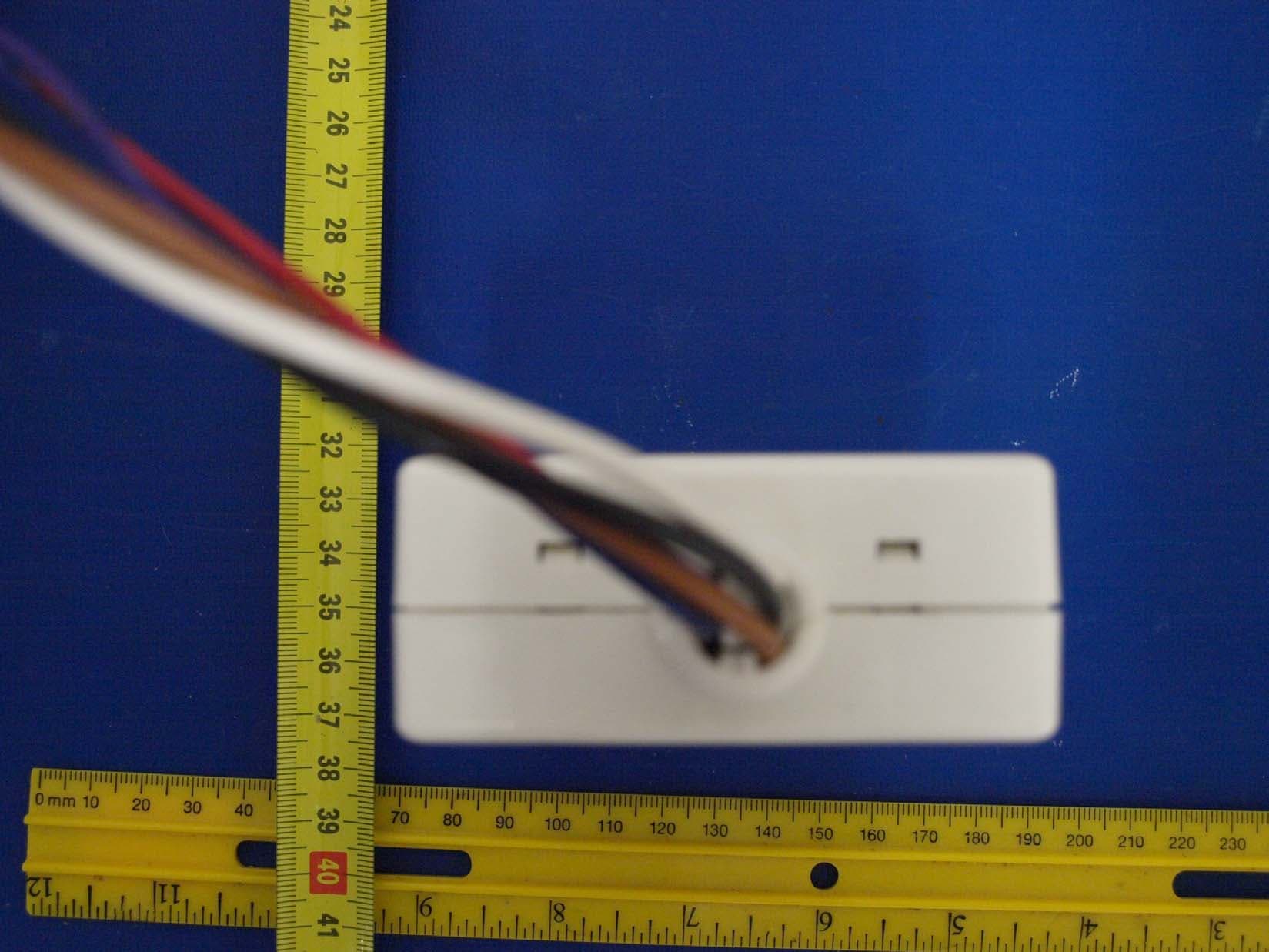
Authorized Agent: Radiometrics Midwest Corporation (815) 293-0772 External EUT Photographs Front of EUT Rear of EUT Right Side of EUT Left Side of EUT Authorized Agent: Radiometrics Midwest Corporation (815) 293-0772 Photographs of EUT Power Supply
ID Label/Location Info
Authorized Agent: Radiometrics Midwest Corporation (815) 293-0772 ID Label/Location Photograph of EUT showing placement of Label Radiometrics Midwest Corporation (815) 293-0772 – [email protected] Drawing of label Label Dimensions:
Internal Photos
Authorized Agent: Radiometrics Midwest Corporation (815) 293-0772 Internal EUT Photographs Photograph of PC Board: Component Side with shield Authorized Agent: Radiometrics Midwest Corporation (815) 293-0772 Connector Side Authorized Agent: Radiometrics Midwest Corporation (815) 293-0772 Under LCD Photograph of PC Board: Component Side without shield Authorized Agent: Radiometrics Midwest Corporation (815) 293-0772 Photograph of PC Board: Component Side without shield Photograph of PC Board: Foil Side
RF Exposure Info
Authorized Agent: Radiometrics Midwest Corporation (815) 293-0772 RF Exposure This calculation is based on the highest EIRP possible from the EUT considering maximum power and antenna gain. The highest output power of the EUT is 251 mW and the gain of the antenna is 0 dBi 1 MINIMUM SEPARATION DISTANCE PER OET 65 The following information provides the minimum separation distance for the EUT, as calculated from FCC OET 65 Appendix B, Table 1B “Guidelines for General Population/Uncontrolled Exposure” SMaximum Peak AntennaMSD Freq.GP limitRF powerGainEIRPEIRPd MHzmW/cm^2 dBmdBdBmwattsmeters 24501240240.2512 0.0447 GP is the limit for general Population/Uncontrolled Exposure MSD is the minimum Seperation Distance Notes on above table. (S) GP limit is from OET 65 table 1B EIRP = Power in dBm + Antenna Gain in dBi MSD (Minimum Separation Distance) = ((EIRP*30)/3770*S))^0.5 NOTE: For mobile or fixed location transmitters, minimum separation distance is 20 cm, even if calculations indicate MPE distance is less 2 RF EVAULATION FOR RSS-102E Since EUT is not handheld and the e.i.r.p. of the Product is 251 mW Peak it is exempt from routine SAR and RF exposure evaluations in accordance to Sections 2.5.1 or 2.5.2 of RSS-102e. The following information provides the calculation for section 4.2 of RSS-102e for the General Public. Peak RFAntennaSeperationRF fieldExposure Freq.PowerGainDistancefrom EUTGP limit MHzdBmdBdBmmWmetersV/mV/m rms 245024024 251.190.20013.761.4 GP is the limit for general Public RF power Effective Note on above table. ERP = (V/m * dist)^2/30
Test Report
Radiometrics Midwest Corporation - www.Radiomet.com Page 1 of 37 Electromagnetic Compatibility Test Report Tests Performed on a Primex Wireless, Inc. AC Temperature Humidity Sensor Transciever, Model SNSATHX Radiometrics Document RP-7072 Product Detail: FCC ID: PZ3-SNSH IC: 4256A-SNSH Equipment type: 2.4 GHz Wifi device Test Standards: US CFR Title 47, Chapter I, FCC Part 15 Subpart C FCC Part 15 CFR Title 47: 2011 Industry Canada RSS-210, Issue 8: 2010 as required for Category I Equipment This report concerns: Original Grant for Certification Tests Performed For: Test Facility: Primex Wireless, Inc. N3211 Highway H Lake Geneva Wisconsin 53147 Radiometrics Midwest Corporation 12 East Devonwood Romeoville, IL 60446 (815) 293-0772 Test Date(s): (Month-Day-Year) July 14 to 27, 2011 Document RP-7072 Revisions: Rev. Issue Date Affected Sections Revised By 0 October 24, 2011 Radiometrics Midwest Corporation www.radiomet.com Testing of the Primex, Inc., Model SNSATHX, AC Temperature Humidity Sensor RP-7072 Rev. 0 Page 2 of 37 Table of Contents 1 ADMINISTRATIVE DATA ................................................................................................................... 3 2 TEST SUMMARY AND RESULTS .....................................................................................................3 2.1 RF Exposure Compliance Requirements ..................................................................................... 3 3 EQUIPMENT UNDER TEST (EUT) DETAILS .................................................................................... 4 3.1 EUT Description ........................................................................................................................... 4 3.1.1 FCC Section 15.203 & RSS-GEN Antenna Requirements .................................................... 4 3.2 Related Submittals ....................................................................................................................... 4 4 TESTED SYSTEM DETAILS .............................................................................................................. 4 4.1 Tested System Configuration ....................................................................................................... 4 4.2 Special Accessories ..................................................................................................................... 5 4.3 Equipment Modifications .............................................................................................................. 5 5 TEST SPECIFICATIONS AND RELATED DOCUMENTS.................................................................. 5 6 RADIOMETRICS’ TEST FACILITIES .................................................................................................5 7 DEVIATIONS AND EXCLUSIONS FROM THE TEST SPECIFICATIONS ......................................... 6 8 CERTIFICATION................................................................................................................................. 6 9 TEST EQUIPMENT TABLE ................................................................................................................ 6 10 TEST SECTIONS.............................................................................................................................. 7 10.1 AC Conducted Emissions........................................................................................................... 7 10.2 Occupied Bandwidth (20 dB or 99%) ....................................................................................... 10 10.3 Peak Output Power .................................................................................................................. 17 10.4 Power Spectral Density ............................................................................................................ 17 10.5 Band-edge Compliance of RF Conducted Emissions .............................................................. 18 10.6 Spurious RF Conducted Emissions.......................................................................................... 21 10.6.1 Radiated Method (18 - 25 GHz) ......................................................................................... 29 10.7 Spurious Radiated Emissions (Restricted Band)...................................................................... 30 10.7.1 Radiated Emissions Field Strength Sample Calculation .................................................... 30 10.7.2 Radiated Emissions Test Results ...................................................................................... 31 10.8 Unintentional Emissions (Receive Mode)................................................................................. 36 Notice: This report must not be reproduced (except in full) without the written approval of Radiometrics Midwest Corporation. Radiometrics Midwest Corporation www.radiomet.com Testing of the Primex, Inc., Model SNSATHX, AC Temperature Humidity Sensor RP-7072 Rev. 0 Page 3 of 37 1 ADMINISTRATIVE DATA Equipment Under Test: A Primex Wireless, Inc., AC Temperature Humidity Sensor Model: SNSATHX Serial Number: None This will be referred to as the EUT in this Report Date EUT Received at Radiometrics: (Month-Day-Year) Test Date(s): (Month-Day-Year) July 14, 2011 July 14 to 27, 2011 Test Report Written By: Test Witnessed By: Joseph Strzelecki Senior EMC Engineer Mike Jonely Primex Wireless, Inc. Radiometrics’ Personnel Responsible for Test: Test Report Approved By Joseph Strzelecki Senior EMC Engineer NARTE EMC-000877-NE Chris W. Carlson Director of Engineering NARTE EMC-000921-NE 2 TEST SUMMARY AND RESULTS The EUT (Equipment Under Test) is an AC Temperature Humidity Sensor, Model SNSATHX, manufactured by Primex Wireless, Inc. The detailed test results are presented in a separate section. The following is a summary of the test results. Spread Spectrum Transmitter Requirements Environmental Phenomena Frequency Range FCC Section RSS- Section Test Result RF…
Text truncated - open the document above for the full version.
Test Setup Photos
Authorized Agent: Radiometrics Midwest Corporation (815) 293-0772 Test Setup Photographs Photograph of Radiated Emissions Test Setup Authorized Agent: Radiometrics Midwest Corporation (815) 293-0772 Photographs of Antenna Conducted Emissions Test Setup Photographs of Conducted Emissions Test Setup
Contact Information
Applicant
Arthur John Mahanna(Product Manager)
Test Firm
Radiometrics Midwest Corp.Joseph Strzelecki
Technical Specifications
| # | Rule Parts | Frequency Range | Power Output |
|---|---|---|---|
| 1 | 15C | 2.41 GHz - 2.46 GHz | 251.00 mW |
Other Applications from Primex Wireless, Inc.
PZ3-SNSE
Mar 15, 2011Emergency Lighting Controller
Equipment Class
DSS - Part 15 Spread Spectrum Transmitter
PZ3-SNSP
Oct 19, 2010Synchronous Network System Personal Series Clock
Equipment Class
DTS - Digital Transmission System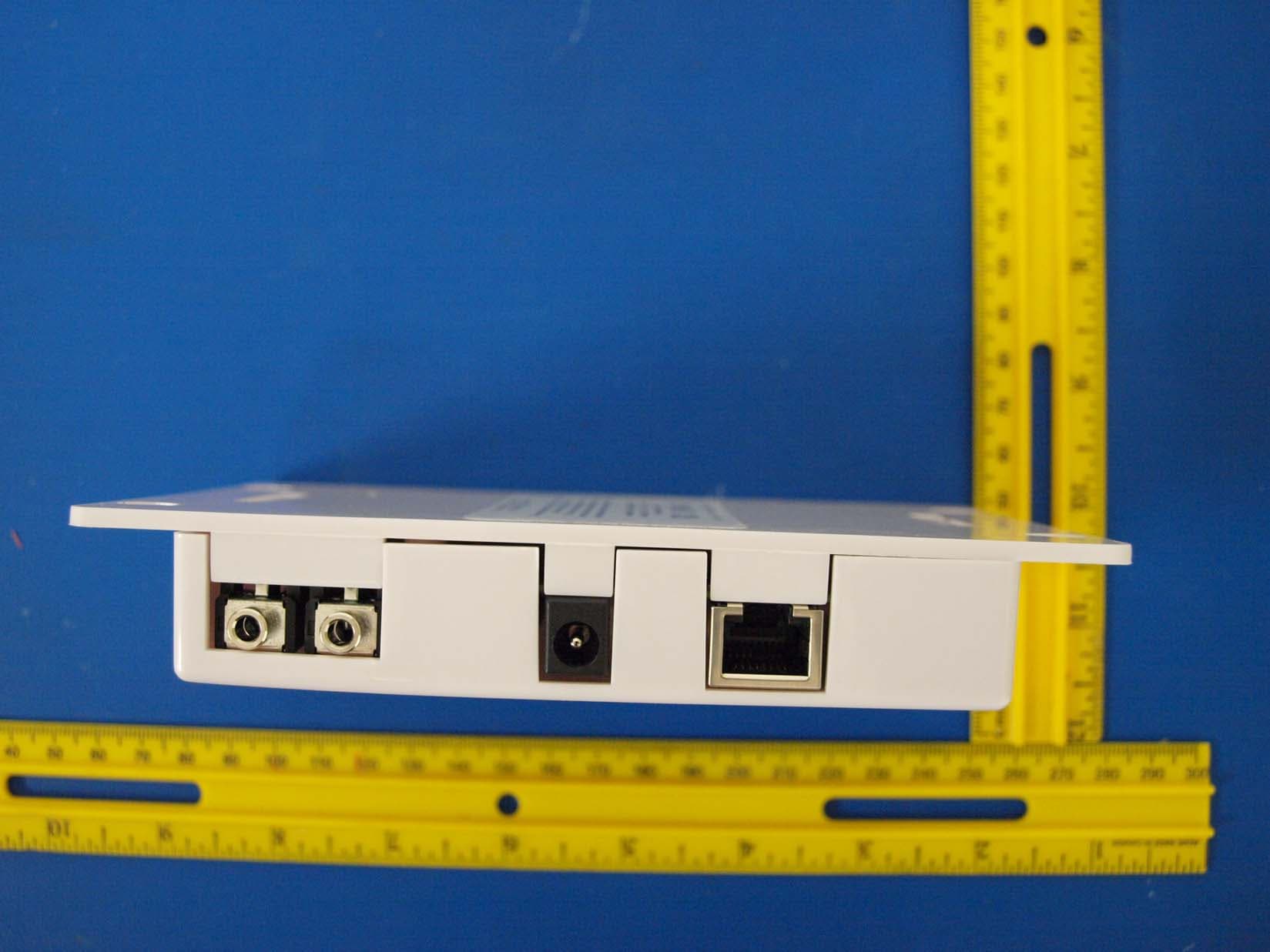
PZ3-SNST
May 03, 2010SYNCHRONOUS NETWORK SYSTEM TEMPERATURE SENSOR
Equipment Class
DTS - Digital Transmission System
PZ3-SNSA
Apr 14, 2008Synchronous Network Analog Clocks
Equipment Class
DTS - Digital Transmission System
PZ3-FM72
Dec 13, 2001Part 90.238 Telemetry Transmitter
Equipment Class
TNB - Licensed Non-Broadcast Station Transmitter