PZ3-SNSTSYNCHRONOUS NETWORK SYSTEM TEMPERATURE SENSOR
Primex Wireless, Inc.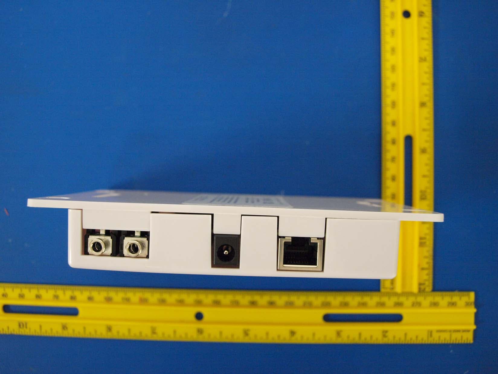
Click to zoom
Application Details
- Equipment Class
- DTS - Digital Transmission System
- Date of Grant
- May 03, 2010
- Application Purpose
- Original Equipment
- Date of Application
- May 03, 2010
- Equipment Note
- SYNCHRONOUS NETWORK SYSTEM TEMPERATURE SENSOR
- Frequency Range
- 2412.00000000 - 2462.00000000
- Company
- Primex Wireless, Inc.
- Country
- United States
Documents & Files
Document Text
Text extracted from the exhibit documents filed with the FCC. Open a document above to read the original.
Users Manual
SNS™ Temperature Sensors User Guide Page ii SNS™ Temperature Sensors User Guide Notices Notices © Copyright 2010, Primex Wireless; all rights reserved. Trademarks SNS and AMP are trademarks of Primex Wireless, Inc. Contact Primex Wireless Web: http://www.primexwireless.com/ Email: [email protected] United States Canada United Kingdom Telephone (800) 537-0464 (800) 330-1459 0800-3896996 Hours 7:00am - 5:00pm Central 7:00am - 5:00pm Central 8:30am – 5:00pm GMT Fax (262) 248-0061 (905) 952-0134 01422-349462 Mailing address Primex Wireless 965 Wells Street Lake Geneva, Wisconsin 53147 Primex Wireless 1310 Kerrisdale Blvd. Unit #4 Newmarket, ON L3Y 8V6 Primex Wireless Limited Dean Clough Halifax West Yorkshire HX3 5AX SNS™ Temperature Sensors User Guide Page iii Contents Contents Introduction .............................................................................................................................................1 Precautions and regulatory compliance statements ...........................................................................1 Safety precautions ........................................................................................................................................1 Equipment precautions .................................................................................................................................1 FCC compliance ...........................................................................................................................................2 FCC radio frequency interference ................................................................................................................2 FCC radiation exposure limits ......................................................................................................................2 SNS temperature sensor specifications ..............................................................................................2 SNS temperature sensor parts and accessories ................................................................................2 Installing SNS temperature sensors .....................................................................................................3 Mounting an SNS temperature sensor unit .........................................................................................3 Connecting the power supply..............................................................................................................3 Connecting sensor probes ..................................................................................................................3 Connecting the network cable.............................................................................................................3 Introduction This user guide describes the features and installation of Primex Wireless Synchronous Network System (SNS™) temperature sensors. SNS temperature sensors are equipped with both a wireless 802.11 b/g interface and a wired Ethernet port interface. Because the sensors support both wired and wireless communications, they integrate easily into an existing network. SNS Temperature sensors can be installed anywhere indoors within range of an 802.11 b/g access point. The temperature sensors are able to connect via an existing wireless LAN (WLAN), supporting a wide variety of security protocols. The initial setup procedure for all SNS temperature sensors can be done in a convenient central location such as a maintenance area or at the final location of the temperature sensor by using the Browser-based Configuration Tool or the discovery mode available in Primex’s Applications Management Platform (AMP™). Once the temperature sensors are configured, settings can be altered using AMP. AMP has features to determine the signal strength of the temperature sensor’s reception. The temperature sensors connect to the WLAN at defined intervals configured with AMP or immediately if there is an alert. Any changes in configuration of a temperature sensor via AMP will be transmitted to the temperature sensor the next time the temperature sensor connects to the WLAN. For detailed instructions on the use of the Browser-based Configuration Tool, please see the Primex Wireless SNS™ Browser-based Configuration Tool User Guide . For detailed instructions on the use of AMP, please see the Primex Wireless Applications Management Platform (AMP™) User Guide . Precautions and regulatory compliance statements This section contains mandatory precautions and regulatory compliance statements. Safety precautions SNS temperature sensors are designed for indoor use only and are not weather protected. Operating the temperature sensor outdoors, or in wet areas is an electrical hazard and may damage the temperature sensor while nullifying the warranty. Equipment precautions • To avoid possible electric shock and damage to an SNS temperature sensor, make sure that it is unplugged when working on it. • For healthcare facilities, temperature sensors are not intended for patient use and must not be installed within 6ft (2m) of patient contact. • SNS temperature sensors are cleanable with a cloth moistened with water or a common disinfectant. Caution Be sure to test any cleaning solutions on a small area of the temperature sensor before using it on the entire temperature sensor. Page 2 SNS™ Temperature Sensors User Guide Introduction SNS temperature sensor specifications FCC compliance Any changes or modifications not expressly approved by the party responsible for compliance could void the user's authority to operate the equipment. FCC radio frequency interference This equipment has been tested and found to comply with the limits for a Class B analog device, pursuant to Part 15 of the FCC Rules. These limits are designed to provide reasonable protection against harmful interference in a residential installation. This equipment generates, uses, and can radiate radio frequency energy and, i…
Text truncated - open the document above for the full version.
Test Report
FCC CFR47 PART 15 SUBPART C INDUSTRY CANADA RSS-210 ISSUE 7 CERTIFICATION TEST REPORT FOR SYNCHRONOUS NETWORK SYSTEM AC POWERED DUAL PROBE TEMPERATURE SENSOR MODEL NUMBER: SNSATPD FCC ID: PZ3-SNST IC: 4256A-SNST REPORT NUMBER: 10U13133-1, Revision A ISSUE DATE: APRIL 27, 2010 Prepared for PRIMEX WIRELESS, INC. 965 WELLS STREET, LAKE GENEVA WI, 53147, U.S.A Prepared by COMPLIANCE CERTIFICATION SERVICES 47173 BENICIA STREET FREMONT, CA 94538, U.S.A. TEL: (510) 771-1000 FAX: (510) 661-0888 REPORT NO: 10U13133-1A DATE: APRIL 27, 2010 FCC ID: PZ3-SNST IC: 4256A-SNST Page 2 of 98 COMPLIANCE CERTIFICATION SERVICES FORM NO: CCSUP4701C 47173 BENICIA STREET, FREMONT, CA 94538, USA TEL: (510) 771-1000 FAX: (510) 661-0888 This report shall not be reproduced except in full, without the written approval of CCS. Revision History Rev. Issue Date Revisions Revised By -- 04/12/10 Initial Issue F. Ibrahim A 04/27/10 Revised IC ID A. Zaffar REPORT NO: 10U13133-1A DATE: APRIL 27, 2010 FCC ID: PZ3-SNST IC: 4256A-SNST Page 3 of 98 COMPLIANCE CERTIFICATION SERVICES FORM NO: CCSUP4701C 47173 BENICIA STREET, FREMONT, CA 94538, USA TEL: (510) 771-1000 FAX: (510) 661-0888 This report shall not be reproduced except in full, without the written approval of CCS. TABLE OF CONTENTS 1. ATTESTATION OF TEST RESULTS.................................................................................... 5 2. TEST METHODOLOGY ........................................................................................................ 6 3. FACILITIES AND ACCREDITATION.................................................................................... 6 4. CALIBRATION AND UNCERTAINTY .................................................................................. 6 4.1. MEASURING INSTRUMENT CALIBRATION ............................................................... 6 4.2. SAMPLE CALCULATION.............................................................................................. 6 4.3. MEASUREMENT UNCERTAINTY................................................................................ 6 5. EQUIPMENT UNDER TEST ................................................................................................. 7 5.1. DESCRIPTION OF EUT................................................................................................ 7 5.2. MAXIMUM OUTPUT POWER....................................................................................... 7 5.3. DESCRIPTION OF AVAILABLE ANTENNAS............................................................... 7 5.4. SOFTWARE AND FIRMWARE..................................................................................... 7 5.5. WORST-CASE CONFIGURATION AND MODE .......................................................... 7 5.6. DESCRIPTION OF TEST SETUP................................................................................. 8 6. TEST AND MEASUREMENT EQUIPMENT ....................................................................... 10 7. ANTENNA PORT TEST RESULTS .................................................................................... 11 7.1. 802.11b MODE IN THE 2.4 GHz BAND...................................................................... 11 7.1.1. 6 dB BANDWIDTH .............................................................................................. 11 7.1.2. 99% BANDWIDTH .............................................................................................. 15 7.1.3. OUTPUT POWER ............................................................................................... 19 7.1.4. AVERAGE POWER ............................................................................................ 23 7.1.5. POWER SPECTRAL DENSITY .......................................................................... 24 7.1.6. CONDUCTED SPURIOUS EMISSIONS............................................................. 28 7.2. 802.11g MODE IN THE 2.4 GHz BAND...................................................................... 35 7.2.1. 6 dB BANDWIDTH .............................................................................................. 35 7.2.2. 99% BANDWIDTH .............................................................................................. 39 7.2.3. OUTPUT POWER ............................................................................................... 43 7.2.4. AVERAGE POWER ............................................................................................ 47 7.2.5. POWER SPECTRAL DENSITY .......................................................................... 48 7.2.6. CONDUCTED SPURIOUS EMISSIONS............................................................. 52 8. RADIATED TEST RESULTS .............................................................................................. 59 8.1. LIMITS AND PROCEDURE ........................................................................................ 59 8.2. TRANSMITTER ABOVE 1 GHz .................................................................................. 60 8.2.1. TX ABOVE 1 GHz FOR 802.11b MODE IN THE 2.4 GHz BAND ....................... 60 8.2.2. TX ABOVE 1 GHz FOR 802.11g MODE IN THE 2.4 GHz BAND ....................... 69 8.3. RECEIVER ABOVE 1 GHz ......................................................................................... 78 8.3.1. RECEIVER ABOVE 1 GHz IN THE 2.4 GHz BAND............................................ 78 REPORT NO: 10U13133-1A DATE: APRIL 27, 2010 FCC ID: PZ3-SNST IC: 4256A-SNST Page 4 of 98 COMPLIANCE CERTIFICATION SERVICES FORM NO: CCSUP4701C 47173 BENICIA STREET, FREMONT, CA 94538, USA TEL: (510) 771-1000 FAX: (510) 661-0888 This report shall not be reproduced except in full, without the written approval of CCS. 8.4. WORST-CASE BELOW 1 GHz................................................................................... 79 9. AC POWER LINE CONDUCTED EMISSIONS ................................................................... 82 10. MAXIMUM PERMISSIBLE EXPOS…
Text truncated - open the document above for the full version.
Test Setup Photos
REPORT NO: 10U13133-1A DATE: APRIL 27, 2010 FCC ID: PZ3-SNST IC: 4256A-SNST Page 90 of 98 COMPLIANCE CERTIFICATION SERVICES FORM NO: CCSUP4701C 47173 BENICIA STREET, FREMONT, CA 94538, USA TEL: (510) 771-1000 FAX: (510) 661-0888 This report shall not be reproduced except in full, without the written approval of CCS. 11. SETUP PHOTOS ANTENNA PORT CONDUCTED RF MEASUREMENT SETUP ANTENNA PORT CONDUCTED PHOTO REPORT NO: 10U13133-1A DATE: APRIL 27, 2010 FCC ID: PZ3-SNST IC: 4256A-SNST Page 91 of 98 COMPLIANCE CERTIFICATION SERVICES FORM NO: CCSUP4701C 47173 BENICIA STREET, FREMONT, CA 94538, USA TEL: (510) 771-1000 FAX: (510) 661-0888 This report shall not be reproduced except in full, without the written approval of CCS. RADIATED RF MEASUREMENT SETUP RADIATED FRONT PHOTO REPORT NO: 10U13133-1A DATE: APRIL 27, 2010 FCC ID: PZ3-SNST IC: 4256A-SNST Page 92 of 98 COMPLIANCE CERTIFICATION SERVICES FORM NO: CCSUP4701C 47173 BENICIA STREET, FREMONT, CA 94538, USA TEL: (510) 771-1000 FAX: (510) 661-0888 This report shall not be reproduced except in full, without the written approval of CCS. RADIATED BACK PHOTO REPORT NO: 10U13133-1A DATE: APRIL 27, 2010 FCC ID: PZ3-SNST IC: 4256A-SNST Page 93 of 98 COMPLIANCE CERTIFICATION SERVICES FORM NO: CCSUP4701C 47173 BENICIA STREET, FREMONT, CA 94538, USA TEL: (510) 771-1000 FAX: (510) 661-0888 This report shall not be reproduced except in full, without the written approval of CCS. RADIATED RF MEASUREMENT SETUP FOR PORTABLE CONFIGURATION X-AXIS FRONT PHOTO REPORT NO: 10U13133-1A DATE: APRIL 27, 2010 FCC ID: PZ3-SNST IC: 4256A-SNST Page 94 of 98 COMPLIANCE CERTIFICATION SERVICES FORM NO: CCSUP4701C 47173 BENICIA STREET, FREMONT, CA 94538, USA TEL: (510) 771-1000 FAX: (510) 661-0888 This report shall not be reproduced except in full, without the written approval of CCS. X-AXIS BACK PHOTO REPORT NO: 10U13133-1A DATE: APRIL 27, 2010 FCC ID: PZ3-SNST IC: 4256A-SNST Page 95 of 98 COMPLIANCE CERTIFICATION SERVICES FORM NO: CCSUP4701C 47173 BENICIA STREET, FREMONT, CA 94538, USA TEL: (510) 771-1000 FAX: (510) 661-0888 This report shall not be reproduced except in full, without the written approval of CCS. Y-AXIS FRONT PHOTO REPORT NO: 10U13133-1A DATE: APRIL 27, 2010 FCC ID: PZ3-SNST IC: 4256A-SNST Page 96 of 98 COMPLIANCE CERTIFICATION SERVICES FORM NO: CCSUP4701C 47173 BENICIA STREET, FREMONT, CA 94538, USA TEL: (510) 771-1000 FAX: (510) 661-0888 This report shall not be reproduced except in full, without the written approval of CCS. Y-AXIS BACK PHOTO REPORT NO: 10U13133-1A DATE: APRIL 27, 2010 FCC ID: PZ3-SNST IC: 4256A-SNST Page 97 of 98 COMPLIANCE CERTIFICATION SERVICES FORM NO: CCSUP4701C 47173 BENICIA STREET, FREMONT, CA 94538, USA TEL: (510) 771-1000 FAX: (510) 661-0888 This report shall not be reproduced except in full, without the written approval of CCS. POWERLINE CONDUCTED EMISSIONS MEASUREMENT SETUP LINE CONDUCTED FRONT PHOTO REPORT NO: 10U13133-1A DATE: APRIL 27, 2010 FCC ID: PZ3-SNST IC: 4256A-SNST Page 98 of 98 COMPLIANCE CERTIFICATION SERVICES FORM NO: CCSUP4701C 47173 BENICIA STREET, FREMONT, CA 94538, USA TEL: (510) 771-1000 FAX: (510) 661-0888 This report shall not be reproduced except in full, without the written approval of CCS. END OF REPORT LINE CONDUCTED BACK PHOTO
Contact Information
Applicant
Arthur John Mahanna(Product Manager)
Test Firm
Compliance Certification ServicesBarbara Judge
Technical Specifications
| # | Rule Parts | Frequency Range | Power Output |
|---|---|---|---|
| 1 | 15C | 2.41 GHz - 2.46 GHz | 196.00 mW |
Other Applications from Primex Wireless, Inc.
PZ3-SNSH
Nov 09, 2011Synchronous Network System AC Temperature & Humidity Sensor
Equipment Class
DTS - Digital Transmission System
PZ3-SNSE
Mar 15, 2011Emergency Lighting Controller
Equipment Class
DSS - Part 15 Spread Spectrum Transmitter
PZ3-SNSP
Oct 19, 2010Synchronous Network System Personal Series Clock
Equipment Class
DTS - Digital Transmission System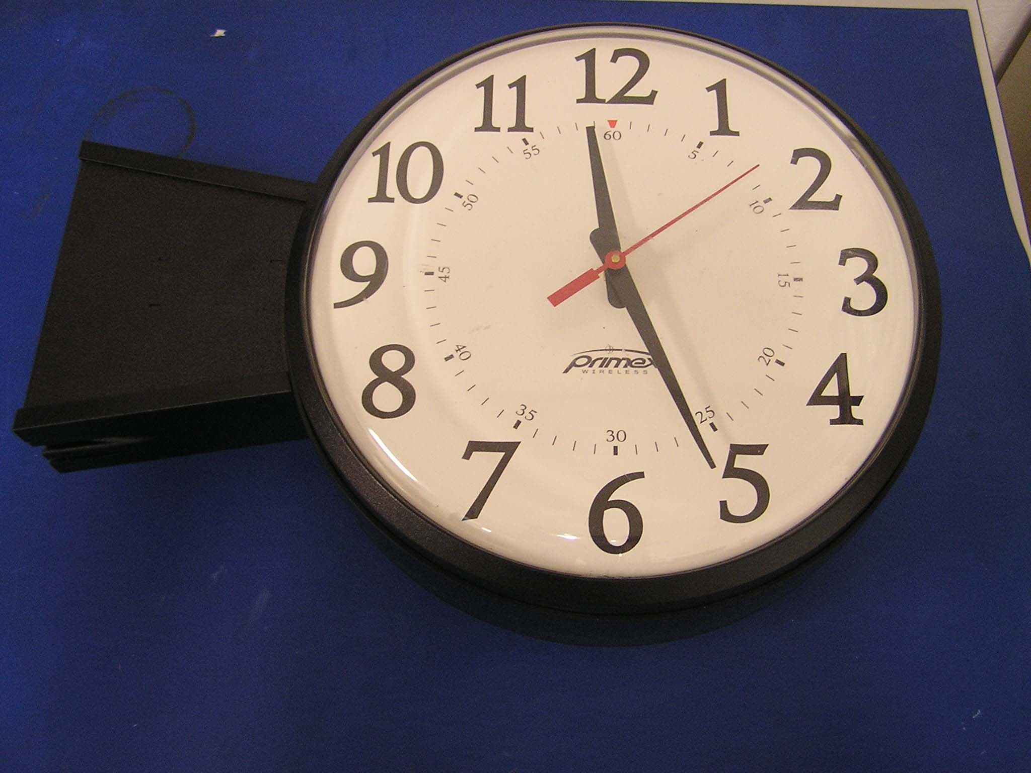
PZ3-SNSA
Apr 14, 2008Synchronous Network Analog Clocks
Equipment Class
DTS - Digital Transmission System
PZ3-FM72
Dec 13, 2001Part 90.238 Telemetry Transmitter
Equipment Class
TNB - Licensed Non-Broadcast Station Transmitter