Q2V-WIIRMCM0012.4GHz Wii Remote Controller
MAXWISE Production Enterprise Ltd.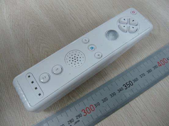
Click to zoom
Application Details
- Equipment Class
- DXX - Part 15 Low Power Communication Device Transmitter
- Date of Grant
- Mar 15, 2010
- Application Purpose
- Original Equipment
- Date of Application
- Mar 15, 2010
- Equipment Note
- 2.4GHz Wii Remote Controller
- Frequency Range
- 2402.00000000 - 2480.00000000
- Country
- China
Documents & Files
Document Text
Text extracted from the exhibit documents filed with the FCC. Open a document above to read the original.
Users Manual
Gaming Remote Bundle DIGWIIRCB 1 Do not disassemble. This will void any and all warranty and may be extremely hazardous. Never push objects of any kind, other than authorized items, into the product as they may touch dangerous voltage points or short out parts that could result in re or electrical shock. Avoid leaving cords in places where they are likely to be walked on or tripped over. Do not pinch, damage, or wrap cords around objects or people. Do not mix di erent brand batteries or insert them in wrong direction. Do not allow children to play with cords. Do not throw or drop the product, or expose them to strong physical shock. Do not expose the product to high temperatures, high humidity or direct sunlight (use in an environment where temperatures range from 42°F to 95°F). Refer to the Instruction Manual that came from your console. Failure to follow these directions may void your warranty. Cautions Contents Wii Remote Remote Silicone Sleeve 3 2 Operation Guide 1. Install batteries Remove the Battery Compartment cover. Install two AA batteries into the Battery Compartment. Make sure the direction is correct. And replace the Battery Compartment cover. 2. Synchronizing the remote with gaming console. You have to synchronize your remote with the gaming console when you the rst time use it. Turn on your gaming console. Remove the battery cover on the back of the remote. Press and release the SYNC. button inside the cover. The Player LEDs will blink. Open the SD Card Slot cover on the front of the gaming console. Press and release the SYNC. button on the inside of the compartment. When the Player LED blinking stops, connection is complete. The LED that is illuminated indicates the player number. Reorient or relocate the receiving antenna. Increase the separation between the equipment and receiver. Connect the equipment into an outlet on a circuit di erent from that to which the receiver is connected. Consult the dealer or an experienced radio/TV technician for help. 4 5 3. Putting the Silicone sleeves on remote and 6 Warning: Changes or modi cations to this unit not expressly approved by the party responsible for compliance could void the user’s authority to operate the equipment. NOTE: This equipment has been tested and found to comply with the limits for a Class B digital device, pursuant to Part 15 of the FCC Rules. These limits are designed to provide reasonable protection against harmful interference in a residential installation. This equipment generates, uses and can radiate radio frequency energy and, if not installed and used in accordance with the instructions, may cause harmful interference to radio communications. This device complies with part 15 of the FCC Rules. Operation is subject to the fol-lowing two conditions: (1) This device may not cause harmful interference, and (2) this device must accept any interference re-ceived, including interference that may cause undesired operation. FCC/regulatory notices This Class B digital apparatus complies with Canadian ICES-003. Cet appareil numérique de la classe B est conforme à la norme NMB-003 du Canada. ICES-003 Statement: However, there is no guarantee that interference will not occur in a particular installation. If this equipment does cause harmful interference to radio or television reception, which can be determined by turning the equipment o and on, the user is encouraged to try to correct the interference by one or more of the following measures: The label was located in the battery compartment.
External Photos
External Photos External Photos
ID Label/Location Info
Label Location and Size
Internal Photos
Internal Photos Internal Photos Internal Photos Internal Photos Internal Photos
Test Report
B Modification Summary Report no: HK09120271-1 Page 2 of 5 Intertek Testing Services Hong Kong Ltd. 2/F., Garment Centre, 576 Castle Peak Road, Kowloon, Hong Kong. Tel: (852) 2173 8888 Fax: (852) 2786 1903 PCB No.: E90-1.1B 2009/08/26 Description Location 1. • Cut three tracks of “L+” pin, “L-“ pin and VCC; • Add three SMD inductors in-between the cutting points as shown. (Wah Shun P/N: MCI-201209-R82KT or equivalent parts) Figure 1, 2 2. • Cut four tracks of pin10-13 of IC U11 (GH2703B); • Add four SMD inductors in-between the cutting points as shown. (Wah Shun P/N: MCI-201209-R82KT or equivalent parts) Figure 3 3. • Change R17 to a jumper as shown. • Cut the track of pin21 of IC U11 (GH2703B) and add a 680Ω SMD resistor in-between the cutting points as shown. Figure 2, 3 4. • Add a 0.1μF ceramic capacitor across the VCC and the GND close to the camera lens module as shown. • Add four 1000pF SMD ceramic capacitors across the four buttons as shown. Figure 4 5. • Cut five tracks of pin4, pin14, pin15, pin8 and pin31 of IC U11 (GH2703B); • Add five 470Ω SMD resistors in-between the cutting points as shown. Figure 3, 5 6. • Cut three tracks of pin9 and pin39 of IC U11 (GH2703B); • Add three SMD inductors in-between the cutting points as shown. (Wah Shun P/N: MCI-201209-R82KT or equivalent parts) Figure 3, 5 Supplier Details for Choke Coils: Supplier Contact person Tel E-mail 1. Wah Shun Enterprises Ltd. Mr. Alan Ng 9190-9263 [email protected] Modified by: Alvin Law Reviewed by: Date: 17 December, 2009 Date: Y. W. Yung 17 December, 2009 B Modification Summary Report no: HK09120271-1 Page 3 of 5 Intertek Testing Services Hong Kong Ltd. 2/F., Garment Centre, 576 Castle Peak Road, Kowloon, Hong Kong. Tel: (852) 2173 8888 Fax: (852) 2786 1903 Figure 1 Figure 2 P1 P1 P3 B Modification Summary Report no: HK09120271-1 Page 4 of 5 Intertek Testing Services Hong Kong Ltd. 2/F., Garment Centre, 576 Castle Peak Road, Kowloon, Hong Kong. Tel: (852) 2173 8888 Fax: (852) 2786 1903 Figure 3 Figure 4 P3 P5 P6 P6 P2 P4 P4 B Modification Summary Report no: HK09120271-1 Page 5 of 5 Intertek Testing Services Hong Kong Ltd. 2/F., Garment Centre, 576 Castle Peak Road, Kowloon, Hong Kong. Tel: (852) 2173 8888 Fax: (852) 2786 1903 Figure 5 Figure 6 P5 P6
Test Report
Report No: GZ09110161-1 FCC ID: Q2V-WIIRMCM001 Page 2 of 28 CONTENT TEST REPORT......................................................................................................................................... 1 CONTENT................................................................................................................................................. 2 1. General Description ...................................................................................................................... 3 1.1 Product Description......................................................................................................... 3 1.2 Related Submittal (s) / Grants....................................................................................... 3 1.3 Test Methodology............................................................................................................ 3 1.4 Test Facility....................................................................................................................... 3 1.5 Measurement Uncertainty.............................................................................................. 4 2. System Test Configuration ........................................................................................................... 5 2.1 Justification....................................................................................................................... 5 2.2 EUT Exercising Software................................................................................................ 5 2.3 Special Accessories........................................................................................................ 5 2.4 Equipment Modification.................................................................................................. 5 2.5 Support Equipment List and Description...................................................................... 5 3. Summary of Test Results .............................................................................................................. 6 3.1 Antenna Requirement..................................................................................................... 6 3.2 Conducted Emission....................................................................................................... 6 3.3 Radiated Emission........................................................................................................... 7 3.3.1 Radiated Emission Limits...................................................................................... 7 3.3.2 Test Setup................................................................................................................ 7 3.3.3 Field Strength Calculation..................................................................................... 8 3.3.4 Radiated Emission Test Data............................................................................... 9 3.3.5 Test Result............................................................................................................. 13 3.4 Band Edges Measurement........................................................................................... 14 3.4.1 Limited of the band edges measurement.......................................................... 14 3.4.2 Test Setup.............................................................................................................. 14 3.4.3 Test Plot................................................................................................................. 15 3.4.4 Test Result............................................................................................................. 18 3.4.5 Transmitter Duty Cycle Calculation FCC Rule 15.35(b, c)............................. 19 4. Appendix I – Photos of Test Setup ............................................................................................. 20 5. Appendix II – Photos of EUT ..................................................................................................... 22 6. Appendix III - Document List..................................................................................................... 28 Report No: GZ09110161-1 FCC ID: Q2V-WIIRMCM001 Page 3 of 28 1. General Description 1.1 Product Description The Equipment Under Test (EUT) is a Bluetooth Wii Remote Controller model: DIGWIIRCB, DGWRBD, WIIRM, WIIMT. It is powered by an internal 3.0V 2×AA Battery. The main function of EUT is working as a controller when playing a game with SONY WII host. Antenna Type: PCB antenna Model(s) DGWRBD, WIIRM, and WIIMT are the same as model DIGWIIRCB in hardware aspect. The difference in model number serves as marketing strategy. For electronic filing, the brief circuit description is saved with filename: Description.pdf. 1.2 Related Submittal (s) / Grants This is an application for certification of a transceiver. 1.3 Test Methodology Radiated emission measurements were performed according to the procedures in ANSI C63.4 (2003). Radiated emission measurement was performed in semi-anechoic chamber room. For radiated emission measurement, preliminary scans were performed in the semi-anechoic chamber only to determine the worst case modes. All radiated tests were performed at an antenna to EUT distance of 3 meters, unless stated otherwise in the "Justification Section" of this Application. 1.4 Test Facility The Semi-Anechoic chamber and shield room used to collect the radiated data and conducted data is Interterk Testing Services Shenzhen Ltd. Kejiyuan Branch and located at 6F, Block D, Huahan Building, Langshan Road, Nanshan District, Shenzhen, P. R. China. This test facility and site measurement data have been fully placed on file with the FCC. Report No: GZ09110161-1 FCC ID: Q2V-WIIRMCM001 Page 4 of 28 Test Equipment List Equipment No. Equipment Manufacturer Model No. Serial No. Cal. Date Due Date SZ061-03 BiConiLog Antenna ETS 3142C 00066460 25-Nov-09 25-May-11 SZ185-01 EMI …
Text truncated - open the document above for the full version.
Test Setup Photos
Report No: GZ09110161-1 FCC ID: Q2V-WIIRMCM001 Page 1 4. Appendix I – Photos of Test Setup Radiated Emission Report No: GZ09110161-1 FCC ID: Q2V-WIIRMCM001 Page 2 Radiated Emission
Contact Information
Applicant
Rui Yang Lin(Managing Director)
Technical Contact
Intertek Testing Services Shenzhen Ltd GuangzhouYannie Wang
[email protected]862082139546
Blk E No. 7-2 Guang Dong Software Science Park · GETDD Guangzhou 510663 · China
Non-Technical Contact
Intertek Testing Services Shenzhen Ltd GuangzhouYannie Wang
[email protected]862082139546
Test Firm
Intertek Testing Services Shenzhen Ltd.Shawn Xing
Technical Specifications
| # | Rule Parts | Frequency Range | Power Output |
|---|---|---|---|
| 1 | 15C | 2.40 GHz - 2.48 GHz | - |
Other Applications from MAXWISE Production Enterprise Ltd.
Q2V5D2007083MW
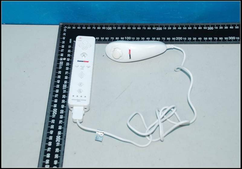
Jul 29, 2012WII WIRELESS CONTROLLER
Equipment Class
DSS - Part 15 Spread Spectrum Transmitter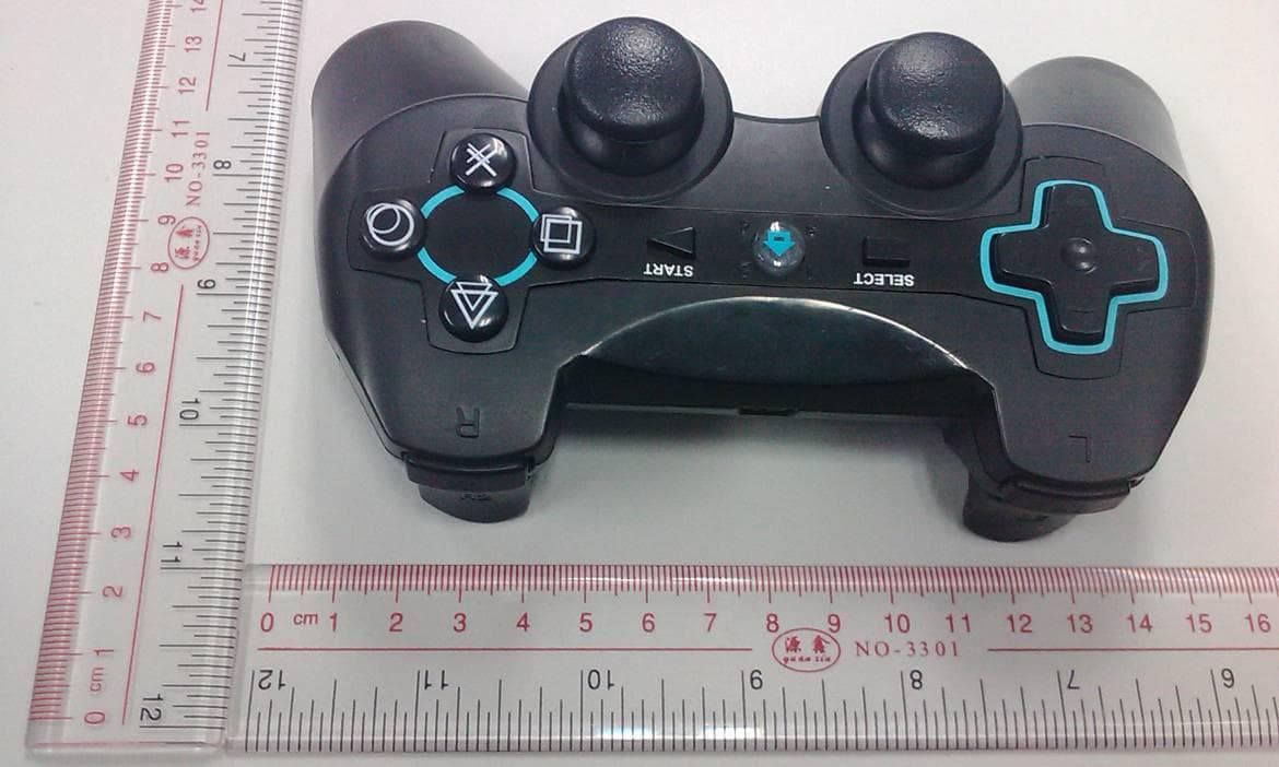
Q2VBTCT5K02047
Nov 02, 2011PS3 BLUETOOTH CONTROLLER
Equipment Class
DSS - Part 15 Spread Spectrum Transmitter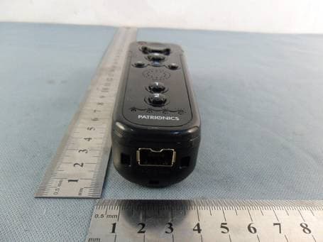
Q2VWIIRMB5D04036
Jun 13, 2011WII Mini Remote Bundle
Equipment Class
DSS - Part 15 Spread Spectrum Transmitter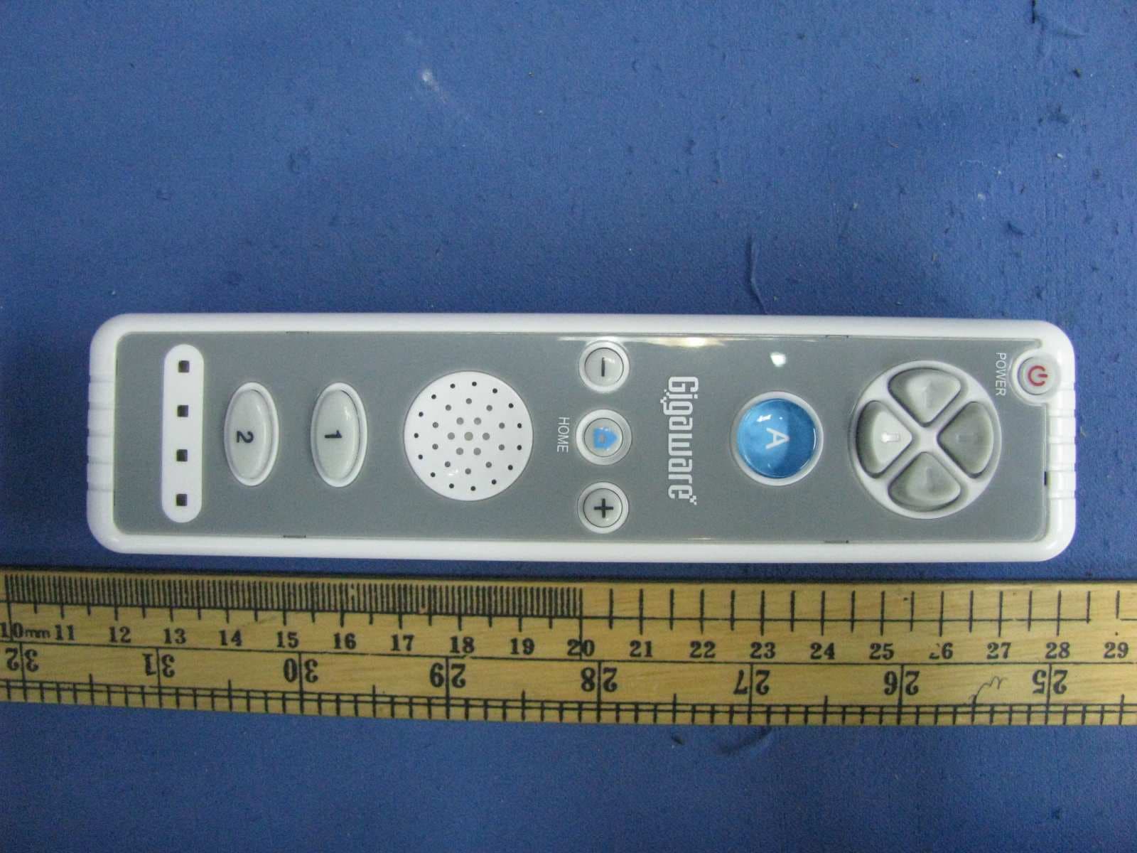
Q2VWIIRM5D20030R
Jul 26, 2010Wii Remote
Equipment Class
DXX - Part 15 Low Power Communication Device Transmitter
Q2VRFPCMWD03A
Jan 10, 2010PS3 Wireless Controller
Equipment Class
DXX - Part 15 Low Power Communication Device Transmitter