Q3K-BSA3XS3.x GHz Integrated Smart Antenna Outdoor Radio Device
Radwin Ltd.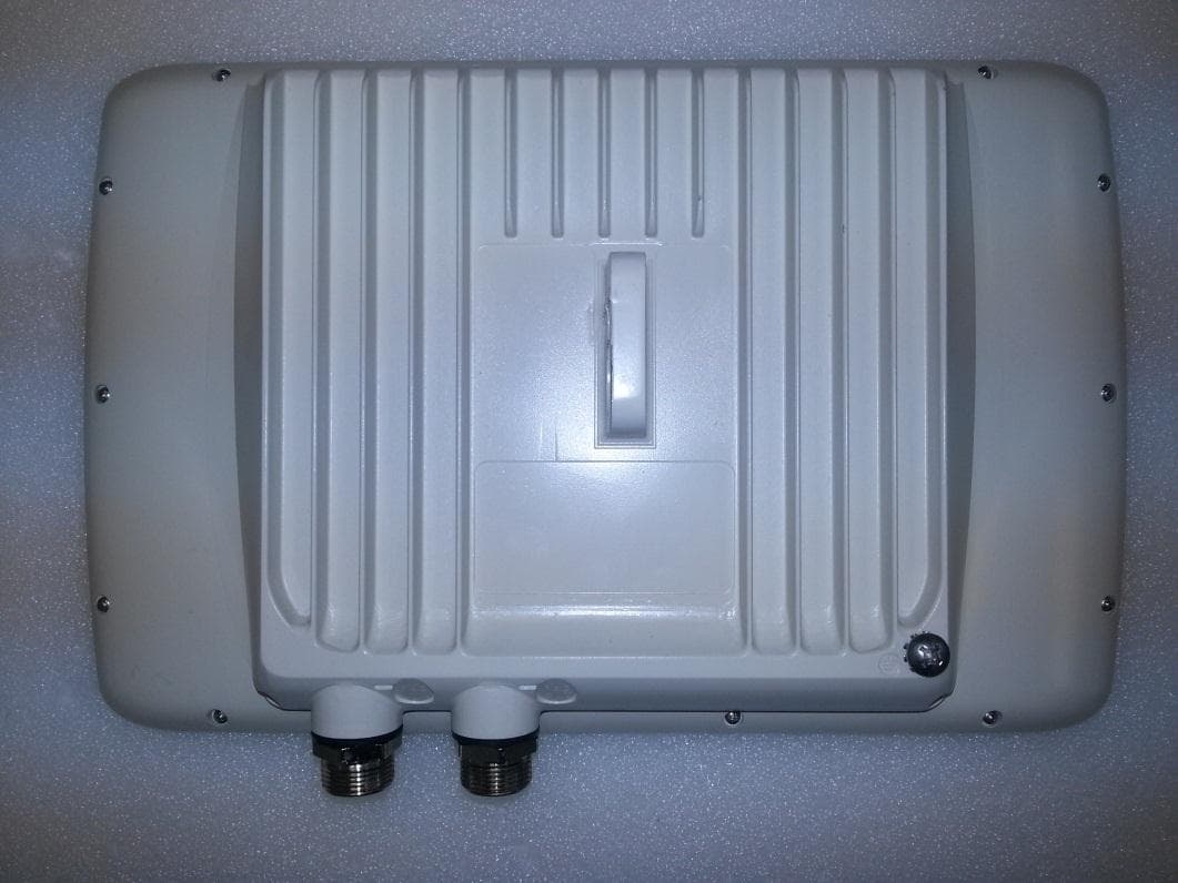
Click to zoom
Application Details
- Equipment Class
- TNB - Licensed Non-Broadcast Station Transmitter
- Date of Grant
- Mar 26, 2015
- Application Purpose
- Original Equipment
- Date of Application
- Mar 24, 2015
- Equipment Note
- 3.x GHz Integrated Smart Antenna Outdoor Radio Device
- Frequency Range
- 3675.00000000 - 3675.00000000
- Company
- Radwin Ltd.
- Country
- Israel
Documents & Files
Document Text
Text extracted from the exhibit documents filed with the FCC. Open a document above to read the original.
Users Manual
RADWIN 2000 JET, RADWIN 5000 JET 3.x GHz Integrated Smart Antenna Outdoor Radio Device REFERENCE GUIDE Regulatory Compliance FCC/IC - Compliance This equipment has been tested and found to comply with the limits for a Class B digital device, pursuant to Part 15 of the FCC Rules and IC RSS standards. These limits are designed to provide reasonable protection against harmful interference in a residential installation. This equipment generates uses and can radiate radio frequency energy and, if not installed and used in accordance with the instructions, may cause harmful interference to radio communications. However, there is no guarantee that interference will not occur in a particular installation. If this equipment does cause harmful interference to radio or television reception, which can be determined by turning the equipment off and on, the user is encouraged to try to correct the interference by one or more of the following measures: • Reorient or relocate the receiving antenna. • Increase the separation between the equipment and receiver. • Connect the equipment into an outlet on a circuit different from that to which the receiver is connected. • Consult the dealer or an experienced radio/TV technician for help. RADWIN Ltd. is not responsible for any radio or communication interference caused by using other than specified or recommended cables and battery or by unauthorized changes or modifications to this equipment. Changes or modifications or modifications not expressly approved by the manufacturer could void the user's authority to operate the equipment. It is the responsibility of the installer to ensure that when using the outdoor antenna kits, only those antennas certified with the product are used. The use of any antenna other than those certified with the product is expressly forbidden by FCC rules 47 CFR part 15.204 and IC RSS standards. Il est de la responsabilité de l'installateur de s'assurer que lorsque vous utilisez les kits d'antennes extérieures, seules les antennes certifiés avec le produit sont utilisés. L'utilisation d'une antenne autre que ceux qui sont certifiés avec le produit est expressément interdite par la réglementation FCC partie 47 CFR 15.204 et IC normes RSS. Outdoor units and antennas should be installed ONLY by experienced installation professionals who are familiar with local building and safety codes and, wherever applicable, are licensed by the appropriate government regulatory authorities. Failure to do so may void the product warranty and may expose the end user or the service provider to legal and financial Caution liabilities. Resellers or distributors of this equipment are not liable for injury, damage or violation of regulations associated with the installation of outdoor units or antennas. The installer should configure the output power level of antennas according to country regulations and antenna type. RADWIN 2000 JET, RADWIN 5000 JET 3.x GHz Reference Guide i Warning Avertissement Les unités extérieures et les antennes doivent être installés que par des professionnels expérimentés d'installation qui sont familiers avec les normes locales et les codes de sécurité et, si applicable, sont agréées par les autorités gouvernementales de réglementation compétents. Ne pas le faire peut annuler la garantie du produit et peuvent exposer l'utilisateur final ou le fournisseur de services d'obligations juridiques et financiers. Revendeurs ou distributeurs de ces équipements ne sont pas responsables des blessures, des dommages ou violation des règlements liés à l'installation des unités extérieures ou des antennes. L'installateur doit configurer le niveau de puissance de sortie des antennes conformément aux réglementations nationales et le type d'antenne. This equipment should be installed and operated with a minimum distance of 53.6cm between the radiator and your body when operating in the 3.65- 3.70 GHz band. Warning Cet équipement doit être installé et utilisé à une distance minimale de 53.6cm entre le radiateur et votre corps lors d'opérations dans la bande de 3.65 à 3.7 GHz The device is granted to operate under FCC/IC certification in the 3.65-3.70 GHz band only. Warning This device complies with Part 15 of the FCC rules and with Industry Canada license- exempt RSS standard(s). Operation is subject to the following two conditions: (1) This device may not cause harmful interference. (2) This device must accept any interference received, including interference that may cause undesired operation. Cet appareil est conforme la norme d'Industrie Canada exempts de licence RSS (s). Son fonctionnement est soumis aux deux conditions suivantes: 1. Cet appareil ne peut pas causer d'interférences, et 2. Cet appareil doit accepter toute interférence, y compris les interférences qui peuvent causer un mauvais fonctionnement de l'appareil. This Class B digital apparatus complies with Canadian ICES-003. Cet appareil numrique de la classe B est conforme la norme NMB-003 du Canada RADWIN 2000 JET, RADWIN 5000 JET 3.x GHz Reference Guide ii Prudence Avertissement Overview The RADWIN 2000 JET, RADWIN 5000 JET 3.x GHz is an Integrated Smart Antenna Outdoor Radio Device operating in the 3.65-3.70 GHz frequency band. It is a TDD OFDM radio supporting 5 MHz, 10 MHz, 20 MHz and 40 MHz channel bandwidths. The RADWIN 2000 JET, RADWIN 5000 JET incorporates an integrated phase array cross- polarized active antenna that supports 2x2 and 3x3 MIMO configuration modes. The antenna is software configurable to operate in 2x2 or 3x3 MIMO modes. The RADWIN 2000 JET, RADWIN 5000 JET also supports software configurable capabilities for PtP and PtMP deployment architecture. The RADWIN 2000 JET model indicates PtP software configuration device. The RADWIN 5000 JET model indicates PtMP software configuration device. The device is certified under the FCC ID: Q3K–BSA3XS and IC: 5100A-BSA3XS Condition of Use The RADWIN 2000 JET, RADWIN 5000 JET is a RADWIN proprietary outdoor radio device. T…
Text truncated - open the document above for the full version.
Cover Letter(s)
Office of Engineering Technology Federal Communications Commission 7435 Oakland Mills Road Columbia, MD 21046 Date: March 12, 2015 Subject; Request for Confidentiality FCC ID: Q3K-BSA3XS To Whom It May Concern, Pursuant to the provisions of Sections 0.457 and 0.459 of Commission's rules (47CFR0.457, 0.459), we are requesting the Commission to withhold the following attachment(s) as confidential document from public disclosure indefinitely. Schematic Diagram Block Diagram Part List Tune Up Procedure Software Configuration Control SDR Security Description Above mentioned document contains detailed system and equipment description are considered as proprietary information in operation of the equipment. The public disclosure of above documents might be harmful to our company and would give competitor an unfair advantage in the market. Furthermore, the product is mounted on top of large towers and mounting poles and serviceable only by the licensee or his designated technicians. It is our understanding that all measurement test reports, FCC ID label format and correspondent during certification review process cannot be granted as confidential documents and those information will be available for public review once the grant of equipment authorization is issued. Sincerely, Signature: Name: Roni Barshan Title: RF Department Manager
Cover Letter(s)
Office of Engineering Technology Federal Communications Commission 7435 Oakland Mills Road Columbia, MD 21046 Date: March 12, 2015 Subject; SDR Request FCC ID: Q3K-BSA3XS Gentlemen, RADWIN Ltd. applies for SDR certification for the RADWIN product RADWIN 2000 JET / RADWIN 5000 JET, 3.x GHz Smart Antenna Outdoor Radio Device. The documents required pursuant KDB 442812 are provided with this application Sincerely, Signature: Name: Roni Barshan Title: RF Department Manager
Cover Letter(s)
www.radwin.com Address goes here Address goes here Address goes here Justification for Using Emission Designator ‘W7W’ RADWIN has chosen the Emission Designator ‘W7W’ for the following reasons: 1. The transmitted signal is based on 802.11n OFDM encoding in modulation formats BPSK, QPSK, 16QAM, 64QM operating in more than two channels and in four channel bandwidths. 2. The transmission can deliver data, voice and video information. 3. The first ‘W’ character defines the definition an emission consists of the main carrier modulated in a combination of amplitude and angle. 4. The character ‘7’ defines that there are more than two channels containing digital information. 5. The second ‘W’ character defines that there is a combination of data, voice and video that can be transmitted. Sincerely, Signature: Name: Roni Barshan Title: RF Department Manager
Cover Letter(s)
Letter of Authorization Company: RADWIN Ltd. Address: 27 Habarzel Street, Tel Aviv, Israel, 6971039 Product Name: 5 GHz Wireless Module Model Number: AP0158770 We authorize MiCOM Labs Inc, 575 Boulder Court, Pleasanton, California 94566, USA, to act on our behalf on all matters concerning the above named equipment. Any individual within MiCOM Labs is authorized to act on our behalf and take action on the application. This shall include the following: Testing Approval applications (includes complete product documentation package, including Confidential information) and procedures Payment of approval fees We declare that MiCOM Labs Inc, 575 Boulder Court, Pleasanton, California 94566, USA, is allowed to forward all information related to the approval project to the applied notified body and to the notification entities and to discuss any issues concerning the approval application. Any and all acts carried out by MiCOM Labs on our behalf shall have the same effect as acts of our own. Name: Roni Barshan Date: March 10, 2015 Title: RF Department Manager Signature of applicant:
Cover Letter(s)
Technical Description 3.x GHz Integrated Smart Antenna Outdoor Radio Device RADWIN 2000 JET / RADWIN 5000 JET The RADWIN 2000 JET / RADWIN 5000 JET is a Point to Point / Point to Multipoint 2x2 and 3x3 MIMO, high power transceiver. It operates in 5, 10, 20 and 40 MHz channel bandwidths in the frequency range 3.65 – 3.70 GHz. It is using OFDM transmission technique in TDD Duplexing method. The RADWIN 2000 JET / RADWIN 5000 JET incorporates an integrated phase array cross-polarized active antenna that supports 2x2 and 3x3 MIMO configuration modes. The RADWIN 2000 JET / RADWIN 5000 JET is powered by a PoE device and has a PoE output port option. The RADWIN 2000 JET is the model name for Point to Point software configuration of the device and the RADWIN 5000 JET is the model name for Point to Multipoint software configuration. Basic features: Operating frequency range: 3650 - 3700 MHz Emission bandwidth: 5, 10, 20, 40 MHz Max output power: 43.4 dBm EIRP Modulation: OFDM (BPSK, QPSK, 16QAM, 64QAM) Duplexing type: TDD The device requires professional installation. Sincerely, Roni Barshan RF Department Manager RADWIN Ltd. RADWIN Ltd. 27 Habarzel St Tel-Aviv, 6971039, Israel, Tel- 972-3-766-2900, Fax-972-3-766-2902
External Photos
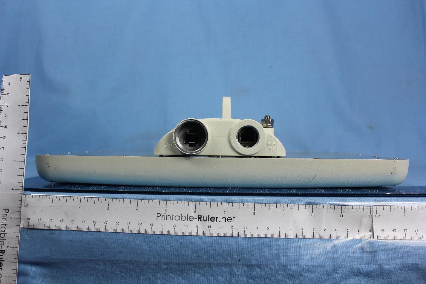
EXTERNAL PHOTOGRAPHS Photo #1: Rear Photo #2: Connectors Panel Photo #3: General View – Front Photo #4: General View – Rear Left Side Photo #5: General View – Rear Right Side
ID Label/Location Info
LABEL AND LABEL LOCATION Photo #1: Label Artwork Photo #2: Label on Device
Internal Photos
RDWN35 Internal Photos
Operational Description
RADWIN2000/5000 JET 1 3/11/15 Office of Engineering Technology Federal Communications Commission 7435 Oakland Mills Road Columbia, MD 21046 Date: March 11, 2015 Subject: Unrestricted Contention Based Protocol for RADWIN 2000 JET, RADWIN 5000 JET To whom it may concern RADWIN Ltd. wishes to market the RADWIN 2000 JET and RADWIN 5000 JET radio devices operating in the frequency band 3.650 - 3.700 GHz and complying with FCC Rule 47CFR, Part 90 Subpart Z. RADWIN 2000 JET devices are for point-to-point radio links, consisting of two radio units, one at each end of the link, enabling wireless connectivity for either urban or rural deployments, supporting both access and backhaul applications, providing Ethernet and TDM data interfaces. RADWIN 5000 JET devices are for point to multi-point systems consisting one base station and several client units (CPEs), enabling wireless connectivity for either urban or rural deployments, supporting both access and backhaul applications, providing Ethernet data interfaces. The RADWIN 2000 JET and RADWIN 5000 JET radio links use the RADWIN TDD air protocol that meets the FCC definition of an “unrestricted” contention based protocol capable of avoiding co- frequency interference with devices using other types of contention-based protocols, by incorporating the mechanisms described in the following sections. RADWIN2000/5000 JET 2 3/11/15 1. Definitions The definitions used within the RADWIN unrestricted protocol algorithm are detailed in this section: a. Radio Frame – Consists of radio transmit and receive portions with a total duration of 1.25 msec. b. Transmit frame – is the transmit portion of a radio frame. The transmit/receive portions can vary. c. TDM Cycle – A RADWIN basic cycle consists of 64 Radio Frames. d. Co-Channel User - A neighboring communication system that operates in a full or partial overlapping channel with the RADWIN system and its received signal strength is strong enough to generate a detected event at the RADWIN system receiver e. Co-Channel User Detection Window (DW) - A sliding window consisting of consecutive radio transmit frames used to determine whether a Co-Channel User exists and should be considered by the RADWIN system algorithm f. Contention Slot - A set of consecutive transmit frames during which the system must not transmit so as to allow a co-channel user to freely utilize the spectrum media. g. Minimum Contention Slot Length – An equipment constant reflecting the number of consecutive transmit frames unconditionally granted to the co-channel user as defined by the equipment user. The default value of the Minimum Contention Slot Length is of 8 transmit frames (equivalent to 10 milliseconds) with a range of 4-16 transmit frames (equivalent to 5 – 20 milliseconds) h. Total Contention Slot Length – The sum of all the Contention Slots that may be generated from the TDM cycle based on the "Sharing Percentage" equipment constant. i. Sharing Percentage – An equipment constant that reflects the required spectrum sharing proportion as defined by the RADWIN system user. The default value of the Sharing Percentage is 50% by default and has a range from 15% to75% by resolution step of 5%. The Sharing Percentage operation is only activated during an occupancy detection scenario. 2. Unrestricted Protocol Description (Item 2.1 in KDB 552295) This section addresses - The key requirements for operation using an unrestricted contention based protocol for recognizing other systems (both similar to RADWIN and different from RADWIN) operating on a co-channel. The strategy for sharing the spectrum by using spectrum sensing to determine if other devices are transmitting and the method used to share the bandwidth under co-channel occupancy Here are the main principles of the RADWIN unrestricted protocol: i. The RADWIN device employs a “listen before transmit” function whose purpose is to detect co-channel transmissions above a detection threshold ii. The detection circuitry measures power level irrespective of the transmitting system’s air interface type RADWIN2000/5000 JET 3 3/11/15 iii. The operating channel is periodically sensed to detect and determine if there are other devices similar to the RADWIN air interface protocol or others transmitting in a co- channel iv. Carrier sensing for co-channel transmission detection is carried out at the start of each RADWIN transmit frame (every 1.25 msec) v. A co-channel user sliding window named as "Detection Window" (DW), composed of four consecutive RADWIN transmit frames (equivalent to 5 milliseconds), is used to determine whether a co-channel user exists vi. Every four consecutive RADWIN transmit frames (DW) (equivalent to 5 milliseconds), the RADWIN system checks if a co-channel transmission was detected in each transmit frame. vii. Upon detection of co-channel occupancy in three out of the four consecutive transmitted frames, the system cancels the next planned transmit frames to enable sharing the bandwidth in the same channel with other transmitting devices viii. The number of the canceled transmit frames is defined by the Contention Slot threshold ix. The Contention Slot attribute defines the consecutive transmit frames during which the system may not transmit so as to allow a co-channel user to freely utilize the channel spectrum x. The "Contention Slot" is defined as follows: a. Minimum Contention Slot Length b. Total Contention Slot Length. The following two diagrams illustrate the RADWIN mechanism of carrier sensing, co-channel detection and occupancy action: Drawing 1: RADWIN2000/5000 JET 4 3/11/15 Drawing 2: Legend: RADWIN2000/5000 JET 5 3/11/15 3. Threshold detection to determine occupancy (Item 2.2 in KDB 552295) Q. Describe how your system determines if another system is using the spectrum. At what detection level – relative to 0 dBi receive antenna gain (busy channel threshold), does the device determine if another system is operating on the spectrum? A. The RADWIN device radio de…
Text truncated - open the document above for the full version.
RF Exposure Info
Tracker: RDWN35-U3 Maximum Permissible Exposure FCC, Part 90 Subpart C §90.1217 Calculations for Maximum Permissible Exposure Levels Power Density = Pd (mW/cm 2 ) = EIRP/(4d 2 ) EIRP = P * G P = Peak output power (mW) G = Antenna numeric gain (numeric) d = Separation distance (cm) Numeric Gain = 10 ^ (G (dBi)/10) The RADWIN 2000 JET and RADWIN 5000 JET has three antenna chains. The peak power in the table below is calculated by assuming a worst case scenario for the maximum gain antenna and output power. The calculated separation distance is worst case found (Operational mode 40 MHz, channel 3675.00 MHz. Calculation was performed using the 17 dBi antenna gain. Because the EUT belongs to the General Population/Uncontrolled Exposure the limit of power density is 1.0 mW/cm 2 Distance (cm) Freq. Band (MHz) Antenna Gain (dBi) Numeric Gain (numeric) Max Peak Output Power (dBm) Peak Output Power (mW) Calculated Power Density @ 20cm Calculated Safe Distance @ 1mW/cm 2 Limit(cm) Minimum Separation Distance (cm) 3,675.0 17 50.12 +28.58 721.1 7.19 53.6 53.6 Note: for mobile or fixed location transmitters the minimum separation distance is 20cm, even if calculations indicate the MPE distance to be less. Specification Maximum Permissible Exposure Limits §90.1217 Systems operating under the provisions of this section shall be operated in a manner that ensures that the public is not exposed to radio frequency levels in excess of the Commission’s guidelines. See §1.1307 (b)(1) of this chapter. Limit = 1 mW / cm 2 from 1.310 Table 1 Laboratory Measurement Uncertainty for Power Measurements Measurement uncertainty 1.33dB
Test Report
COVER PAGE Test of RADWIN 2000 JET, RADWIN 5000 JET To: FCC Part 90 Subpart Z & IC RSS-197 Test Report Serial No.: RDWN35-U3 Rev A MiCOM Labs is an ISO 17025 Accredited Testing Laboratory TEST REPORT FROM Test of: RADWIN 2000 JET, RADWIN 5000 JET To: FCC Part 90 Subpart Z & IC RSS-197 Test Report Serial No.: RDWN35-U3 Rev A This report supersedes NONE Manufacturer: RADWIN Ltd 27 Habarzel Street Tel Aviv, 6971039 Israel Product Function: 3.x GHz Integrated Smart Antenna Outdoor Radio Service Copy No: pdf Issue Date: 19th March 2015 This Test Report is Issued Under the Authority of; MiCOM Labs, Inc. 575 Boulder Court Pleasanton, CA 94566 USA Phone: +1 (925) 462-0304 Fax: +1 (925) 462-0306 www.micomlabs.com TESTING CERT #2381.01 Title: To: Serial #: Issue Date: Page: RADWIN 2000 JET, RADWIN 5000 JET FCC Part 90 Subpart Z & IC RSS-197 RDWN35-U3 Rev A 19th March 2015 3 of 192 This test report may be reproduced in full only. The document may only be updated by MiCOM Labs personnel. Any changes will be noted in the Document History section of the report. MiCOM Labs Inc, 575 Boulder Court, Pleasanton, California 94566 USA, Phone: 925.462.0304, Fax: 925.462.0306, www.micomlabs.com This page has been left intentionally blank Title: To: Serial #: Issue Date: Page: RADWIN 2000 JET, RADWIN 5000 JET FCC Part 90 Subpart Z & IC RSS-197 RDWN35-U3 Rev A 19th March 2015 4 of 192 This test report may be reproduced in full only. The document may only be updated by MiCOM Labs personnel. Any changes will be noted in the Document History section of the report. MiCOM Labs Inc, 575 Boulder Court, Pleasanton, California 94566 USA, Phone: 925.462.0304, Fax: 925.462.0306, www.micomlabs.com TABLE OF CONTENTS ACCREDITATION, LISTINGS and RECOGNITION ...................................................... 6 TESTING ACCREDITATION ......................................................................................... 6 RECOGNITION .............................................................................................................. 7 PRODUCT CERTIFICATION ......................................................................................... 8 1. TEST RESULT CERTIFICATE .............................................................................. 10 2. REFERENCES AND MEASUREMENT UNCERTAINTY ..................................... 11 2.1. Normative References ........................................................................................ 11 2.2. Test and Uncertainty Procedures ........................................................................ 11 3. PRODUCT DETAILS AND TEST CONFIGURATIONS ........................................ 12 3.1. Technical Details ................................................................................................. 12 3.2. Scope of Test Program ....................................................................................... 13 3.3. Equipment Model(s) and Serial Number(s).......................................................... 18 3.4. Antenna Details ................................................................................................... 18 3.5. Cabling and I/O Ports .......................................................................................... 18 3.6. Test Configurations ............................................................................................. 19 3.7. Equipment Modifications ..................................................................................... 19 3.8. Deviations from the Test Standard ...................................................................... 19 4. TEST EQUIPMENT CONFIGURATIONS ............................................................. 20 4.1. Conducted Testing .............................................................................................. 20 4.2. Radiated Testing ................................................................................................. 22 4.3. ac Wireline ......................................................................................................... 24 5. MEASUREMENT AND PRESENTATION OF TEST DATA ................................. 25 6. TEST SUMMARY .................................................................................................. 26 7. TEST RESULTS .................................................................................................... 27 7.1. D evice Characteristics ........................................................................................ 27 7.1.1. Occupied Bandwidth ............................................................................ 27 7.1.2. Peak Output Power .............................................................................. 32 7.1.3. Power Spectral Density ........................................................................ 37 7.1.4. Maximum Permissible Exposure .......................................................... 42 7.1.5. Frequency Stability; Temperature Variations, and Voltage Variations .. 43 7.1.6. Spurious Emissions at Antenna Terminals ........................................... 45 7.1.7. Radiated Spurious Emissions .............................................................. 51 7.1.8. AC Wireline Conducted Emissions (150 kHz – 30 MHz) ...................... 62 Title: To: Serial #: Issue Date: Page: RADWIN 2000 JET, RADWIN 5000 JET FCC Part 90 Subpart Z & IC RSS-197 RDWN35-U3 Rev A 19th March 2015 5 of 192 This test report may be reproduced in full only. The document may only be updated by MiCOM Labs personnel. Any changes will be noted in the Document History section of the report. MiCOM Labs Inc, 575 Boulder Court, Pleasanton, California 94566 USA, Phone: 925.462.0304, Fax: 925.462.0306, www.micomlabs.com 8. TEST SET-UP PHOTOGRAPHS .......................................................................... 65 8.1. Conducted Measurement Test Set-Up ................................................................ 65 8.2. Radiated Spurious Emissions …
Text truncated - open the document above for the full version.
Test Setup Photos
RDWN35 Test Set up Photos Conducted RF Radiated RF
Contact Information
Applicant
Shlomo Weiss(Standardization Officer)
Technical Contact
MiCOM LabsBill Graff
[email protected](925)4620304
575 Boulder Court · Pleasanton, California · United States
Test Firm
MiCOM LabsGordon Hurst
Technical Specifications
| # | Rule Parts | Frequency Range | Power Output | Emission | Tolerance |
|---|---|---|---|---|---|
| 4 | 9 | 3.67 GHz - 3.67 GHz | 720.00 mW | 40M0W7W | 0.89 ppm |
Other Applications from Radwin Ltd.
Q3K-PTP5GAX
Feb 25, 20235 GHz High Performance PtP Outdoor Unit
Equipment Class
NII - Unlicensed National Information Infrastructure TX
Q3K-NEO5X
Apr 27, 2021Single Carrier 5.x GHz Base Station with Beamforming Antenna, Dual Carrier 5.x GHz Base Station with Beamforming Antenna
Equipment Class
NII - Unlicensed National Information Infrastructure TX
Q3K-5XSUALMOD
Apr 13, 20215 GHz SU/Alpha Board
Equipment Class
NII - Unlicensed National Information Infrastructure TX
Q3K-5XACMODMS
Sep 13, 20205 GHz MS RF Module
Equipment Class
NII - Unlicensed National Information Infrastructure TX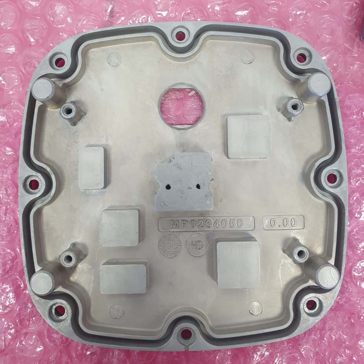
Q3K-TRBR600G
Aug 25, 2020Point to point/point to multipoint 57-71 GHz radio transceiver
Equipment Class
DXX - Part 15 Low Power Communication Device Transmitter