Q3KAMWL1000Hybrid System Tranmceiver
Radwin Ltd.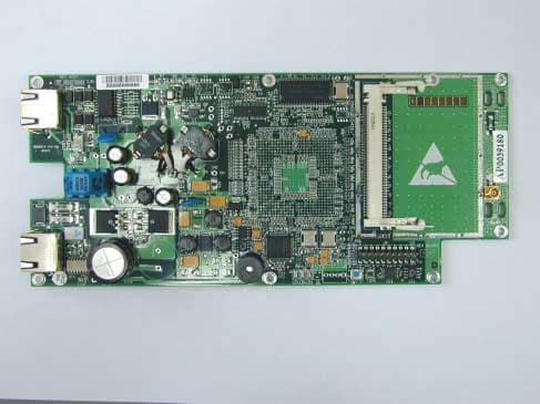
Click to zoom
Application Details
- Equipment Class
- DTS - Digital Transmission System
- Date of Grant
- Jun 13, 2004
- Application Purpose
- Original Equipment
- Date of Application
- Jun 13, 2004
- Equipment Note
- Hybrid System Tranmceiver
- Frequency Range
- 5740.00000000 - 5835.00000000
- Company
- Radwin Ltd.
- Country
- Israel
Documents & Files
Document Text
Text extracted from the exhibit documents filed with the FCC. Open a document above to read the original.
Users Manual
AirMux-200 Installation and Operation Manual Point-to-Point Wireless TDM/IP Multiplexer AirMux-200 Point-to-Point Wireless TDM/IP Multiplexer Installation and Operation Manual Notice This manual contains information that is proprietary to RAD Data Communications Ltd. ("RAD"). No part of this publication may be reproduced in any form whatsoever without prior written approval by RAD Data Communications. Right, title and interest, all information, copyrights, patents, know-how, trade secrets and other intellectual property or other proprietary rights relating to this manual and to the AirMux-200 and any software components contained therein are proprietary products of RAD protected under international copyright law and shall be and remain solely with RAD. AirMux-200 is a registered trademark of RAD. No right, license, or interest to such trademark is granted hereunder, and you agree that no such right, license, or interest shall be asserted by you with respect to such trademark. You shall not copy, reverse compile or reverse assemble all or any portion of the Manual or the AirMux-200. You are prohibited from, and shall not, directly or indirectly, develop, market, distribute, license, or sell any product that supports substantially similar functionality as the AirMux-200, based on or derived in any way from the AirMux-200. Your undertaking in this paragraph shall survive the termination of this Agreement. This Agreement is effective upon your opening of the AirMux-200 package and shall continue until terminated. RAD may terminate this Agreement upon the breach by you of any term hereof. Upon such termination by RAD, you agree to return to RAD the AirMux- 200 and all copies and portions thereof. For further information contact RAD at the address below or contact your local distributor. International Headquarters RAD Data Communications Ltd. 24 Raoul Wallenberg St. Tel Aviv 69719 Israel Tel: 972-3-6458181 Fax: 972-3-6498250 E-mail: [email protected] U.S. Headquarters RAD Data Communications Inc. 900 Corporate Drive Mahwah, NJ 07430 USA Tel: (201) 529-1100, Toll free: 1-800- 444-7234 Fax: (201) 529-5777 E-mail: [email protected] © 2002–2004 RAD Data Communications Ltd. Publication No. xxx-200-05/04 Limited Warranty RAD warrants to DISTRIBUTOR that the hardware in the AirMux-200 to be delivered hereunder shall be free of defects in material and workmanship under normal use and service for a period of twelve (12) months following the date of shipment to DISTRIBUTOR. If, during the warranty period, any component part of the equipment becomes defective by reason of material or workmanship, and DISTRIBUTOR immediately notifies RAD of such defect, RAD shall have the option to choose the appropriate corrective action: a) supply a replacement part, or b) request return of equipment to its plant for repair, or c) perform necessary repair at the equipment's location. In the event that RAD requests the return of equipment, each party shall pay one-way shipping costs. RAD shall be released from all obligations under its warranty in the event that the equipment has been subjected to misuse, neglect, accident or improper installation, or if repairs or modifications were made by persons other than RAD's own authorized service personnel, unless such repairs by others were made with the written consent of RAD. The above warranty is in lieu of all other warranties, expressed or implied. There are no warranties which extend beyond the face hereof, including, but not limited to, warranties of merchantability and fitness for a particular purpose, and in no event shall RAD be liable for consequential damages. RAD shall not be liable to any person for any special or indirect damages, including, but not limited to, lost profits from any cause whatsoever arising from or in any way connected with the manufacture, sale, handling, repair, maintenance or use of the AirMux-200, and in no event shall RAD's liability exceed the purchase price of the AirMux-200. DISTRIBUTOR shall be responsible to its customers for any and all warranties which it makes relating to AirMux-200 and for ensuring that replacements and other adjustments required in connection with the said warranties are satisfactory. Software components in the AirMux-200 are provided "as is" and without warranty of any kind. RAD disclaims all warranties including the implied warranties of merchantability and fitness for a particular purpose. RAD shall not be liable for any loss of use, interruption of business or indirect, special, incidental or consequential damages of any kind. In spite of the above RAD shall do its best to provide error-free software products and shall offer free Software updates during the warranty period under this Agreement. RAD's cumulative liability to you or any other party for any loss or damages resulting from any claims, demands, or actions arising out of or relating to this Agreement and the AirMux-200 shall not exceed the sum paid to RAD for the purchase of the AirMux-200. In no event shall RAD be liable for any indirect, incidental, consequential, special, or exemplary damages or lost profits, even if RAD has been advised of the possibility of such damages. This Agreement shall be construed and governed in accordance with the laws of the State of Israel. General Safety Instructions The following instructions serve as a general guide for the safe installation and operation of telecommunications products. Additional instructions, if applicable, are included inside the manual. Safety Symbols This symbol may appear on the equipment or in the text. It indicates potential safety hazards regarding product operation or maintenance to operator or service personnel. Danger of electric shock! Avoid any contact with the marked surface while the product is energized or connected to outdoor telecommunication lines. . Protective earth: the marked lug or terminal should be connected to the building protective earth bus. Some products may be equipped with…
Text truncated - open the document above for the full version.
Block Diagram
IXP4xx Network Processor Flash (4/8/16MB) SDRAM (32/64/128MB) Mini PCI Interface Ethernet PHY EEPROM Temp. Sensor MII PCI Bus IIC Bus Exp. Bus LEDs Conf. H/W JTAG Port Debug Port Serial Port JTAG DC Supplies PoE Control Lines MAC Address RESET & W.Dog
Cover Letter(s)
34 Habarzel street, Tel Aviv 69710, Israel tel. +972 3645 5577 FAX: +972 3765 7535 May 31, 2004 American TCB 6731 Whittier Ave Suite C110 McLean, VA 22101 USA Subject: Request for confidentiality for a wireless point–to-point broadband transmission system, FCC ID:Q3KAMWL1000 Dear Gentlemen, We apply to you with request to withhold Radwin Ltd. trade secrets in Application for Certification for FCC ID: Q3KAMWL1000. These trade secrets can be found in the transmitter schematic diagram, file name “Schematics_15885” (2 pages of this Application). Many thanks in advance. Sincerely yours, David Ben-Chaim Radio group manager Radwin Ltd
Cover Letter(s)
RADWIN Ltd. 34 Habarzel St Tel-Aviv, 69710, Israel, Tel- 972-3-645-5577, Fax-972-3-765-7535 Date: May 31 st 2004 Subject: Compliance of Model AirMux I would like to bring to your attention that the AirMux/WinLink system that was tested at Hermon Labs 05/2004 for FCC standards have two commercial models: AirMux-200 / WinLink 1000. Therefore User Manual for AirMux-200 is valid for WinLink 1000. Please consider in reports and certifications. Sincerely Dan Weitzman
Cover Letter(s)
American Telecommunications Certification Body Inc. 6731 Whittier Ave, McLean, VA 22101 June 6, 2004 RE: FCC ID: Q3KAMWL1000_ATCB001398 Attention: Alex Usoskin I have a few comments on this Application. Please note that further comments may arise in response to answers provided to the questions below. 1. Please note that the “compliance letter” states there are two models for this device. One model is the AirMUX-200 and the other is the WinLink 1000. Please explain the differences between these two models. Dennis Ward mailto:[email protected] The items indicated above must be submitted before processing can continue on the above referenced application. Failure to provide the requested information may result in application termination. Correspondence should be considered part of the permanent submission and may be viewed from the Internet after a Grant of Equipment Authorization is issued. Please do not respond to this correspondence using the email reply button. In order for your response to be processed expeditiously, you must submit your documents through the AmericanTCB.com website. Also, please note that partial responses increase processing time and should not be submitted. Any questions about the content of this correspondence should be directed to the sender.
Cover Letter(s)
HERM O N LA BO RA TO RIES June 10, 2004 American TCB 6731 Whittier Ave Suite C110 McLean, VA 22101 Attn: Mr. D. Ward, Examining Engineer RE: your e-mail dated June 6, 2004; Radwin Ltd. FCC ID: Q3KAMWL1000, ATCB001398 Dear Mr. Ward, Please find below the answers to your questions. 1) Radwin Ltd. confirms that the two products WinLink 1000 and AirMux-200 are exactly the same, just they have 2 commercial names for marketing purposes. 2) Revised file “Label_location_15885_rev1” was uploaded via Label Location folder on June 10, 2004. 3) Revised file “User_Manual_15885_rev1” with corrected page 14 (about class B requirements) was uploaded via Users Manual folder on June 10, 2004. Many thanks for your help. Sincerely, Marina Cherniavsky, certification engineer Hermon Laboratories
External Photos
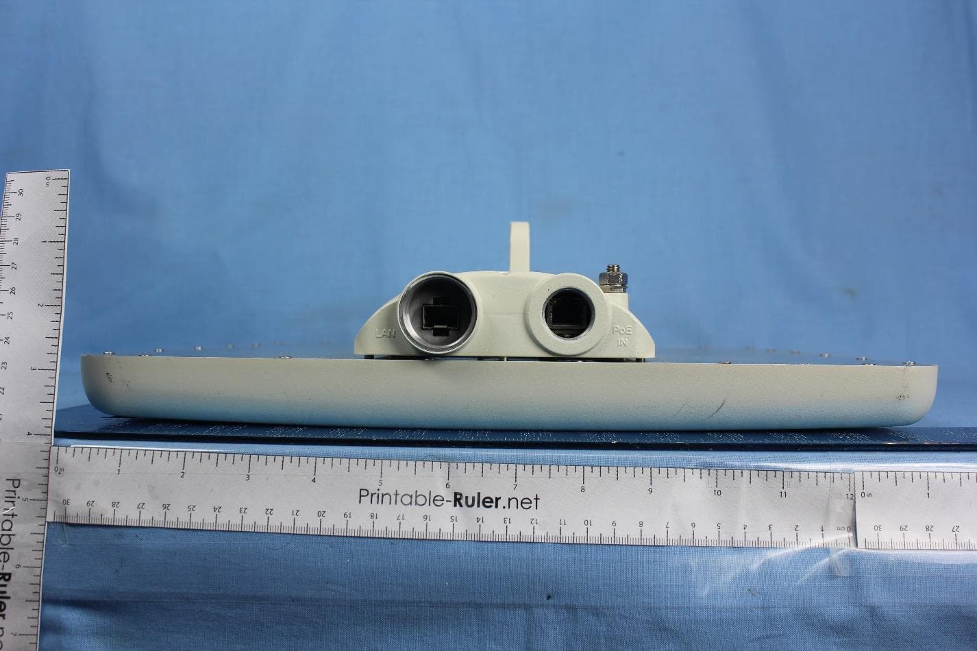
FCC ID:Q3KAMWL1000 Date: May 2004 Page 1 of 4 EXTERNAL PHOTOGRAPHS This document contains 3 photographs FCC ID:Q3KAMWL1000 Date: May 2004 Page 2 of 4 Photograph No.1 Winlink 1000/F58 and AirMux 200/F58 outdoor radio terminal Front view FCC ID:Q3KAMWL1000 Date: May 2004 Page 3 of 4 Photograph No.2 Winlink 1000/F58 and AirMux 200/F58 outdoor radio terminal Bottom view FCC ID:Q3KAMWL1000 Date: May 2004 Page 4 of 4 Photograph No.3 Winlink 1000/F58 and AirMux 200/F58 outdoor radio terminal Side view
ID Label/Location Info
An outdoor radio terminal shall bear the label with FCC ID:Q3KAMQWL1000 and RADWIN logo on a back panel as shown in the drawing below: The statement according to FCC part 15 section 15.19 is affixed to indoor unit, connected by wires to outdoor unit and marketed together. WINLINK Manufacturer: Radwin Ltd. This device complies with Part 15 of the FCC Rules. Operation is subject to the following two conditions: (1) This device may not cause harmful interference, and (2) this device must accept any interference received, including interference that may cause undesired operation.
Internal Photos
FCC ID:Q3KAMWL1000 Date: May 2004 Page 1 of 11 INTERNAL PHOTOGRAPHS This document contains 10 photographs FCC ID:Q3KAMWL1000 Date: May 2004 Page 2 of 11 Photograph No.1 Winlink 1000/F58 and AirMux 200/F58 outdoor radio unit Internal view FCC ID:Q3KAMWL1000 Date: May 2004 Page 3 of 11 Photograph No.2 Winlink 1000/F58 and AirMux 200/F58 Internal view without cover FCC ID:Q3KAMWL1000 Date: May 2004 Page 4 of 11 Photograph No.3 Winlink 1000/F58 and AirMux 200/F58 Internal view without RF board FCC ID:Q3KAMWL1000 Date: May 2004 Page 5 of 11 Photograph No.4 Winlink 1000/F58 and AirMux 200/F58 Modem and RF board FCC ID:Q3KAMWL1000 Date: May 2004 Page 6 of 11 Photograph No.5 Winlink 1000/F58 and AirMux 200/F58 Modem and RF board second side FCC ID:Q3KAMWL1000 Date: May 2004 Page 7 of 11 Photograph No.6 Winlink 1000/F58 and AirMux 200/F58 Main board FCC ID:Q3KAMWL1000 Date: May 2004 Page 8 of 11 Photograph No.7 Winlink 1000/F58 and AirMux 200/F58 Main board second side FCC ID:Q3KAMWL1000 Date: May 2004 Page 9 of 11 Photograph No.8 Winlink 1000/F58 and AirMux 200/F58 RF board with cover removed FCC ID:Q3KAMWL1000 Date: May 2004 Page 10 of 11 Photograph No.9 Winlink 1000/F58 and AirMux 200/F58 RF board close view FCC ID:Q3KAMWL1000 Date: May 2004 Page 11 of 11 Photograph No.10 Winlink 1000/F58 and AirMux 200/F58 RF amplifier
Operational Description
AirMux-200 Family High Capacity License Exempt Radio Relay Features High data rate of up to 48Mbps Long range of up to 80 Km Integrated solution for E1/T1s and Ethernet interfaces Carrier-class solution Compliant with FCC and ETSI regulations Description AirMux-200 family of products is a carrier- class, high capacity and low cost Point to Point broadband wireless transmission system. It packs Legacy TDM and Ethernet services over 5.x GHz unlicensed bands and is suitable for deployment in FCC or ESTI regulated countries. AirMux-200 , which provides high capacity connectivity of up to 48 Mbps, allows for the rapid deployment of E1/T1s and Ethernet links at a fraction of alternatives cost. AirMux-200 is based on RADWIN’s SmartPacket technology, which enables high performance and reliability. AirMux-200 is the right solution for customers requiring immediate deployment of affordable carrier-class high capacity connectivity in the license exempt frequencies. Benefits Short Time to Service License exempt frequencies remove regulatory delays Wireless connectivity instead of private line leasing from service providers Compact integrated solution that is simple to install and operate Carrier Class Solution High reliability and availability based on robust air-interface TDM transmission complies with all Telecom requirements. Typical Applications Remote Sites' Connectivity AirMux-200 is offered to enterprises with multiple sites that require a cost effective and transparent connection of their LAN and PBX systems across their various campuses Broadband Access AirMux-200 provides broadband access services, such broadband Ethernet and Leased Lines, to Small and Medium Enterprises (SME). Backhauling AirMux-200 backhauls traffic from cellular base stations, Hotspots or point of presence (POP) of wireless ISP's to backbone network. Specifications Configuration Architecture Indoor Unit (IDU) and Outdoor Unit (ODU) IDU to ODU Interface Outdoor CAT-5 cable Maximum length of 100m Radio Frequency 5.725 – 5.850 GHz 5.470 – 5.725 GHz Data Rate Configurable up to 48Mbps Channel BW 20MHz Duplex Technique TDD System Gain 160dB Modulation OFDM - BPSK, QPSK, 16QAM, 64QAM Transmit Power FCC: 18dBm (max) ETSI: 7dbm (Max, limited by the regulation) Received Dynamic range >60dB Integrated Antenna Gain 23dbi Type Flat panel Polarization Linear (V or H) Beam Width 9° Optional External Antenna Gain: 28dbi Type Flat panel Polarization Linear (V or H) Beam Width 4.5° LAN Interface Type 10/100BaseT, Auto-negotiation Framing/Coding IEEE 802.3/U Bridging Self-learning up to 2000 MAC addresses Traffic Handling MAC layer bridging, self-learning Data Latency 2msec typical Line Impedance 100Ω VLAN Support Transparent Connector RJ-45 E1/T1 Interface Framing Unframed (Transparent) Timing Plesynchronous (Independent Tx and Rx timing) Latency 8 msec Line Impedance 120/100Ohm, balanced Number of Ports 1,2,4 Connector RJ-45 Jitter & Wander G.823, G.824 Management Protocol SNMP based Network Management Based on SNMPC Management Interface Ethernet 10/100BT RS-232 Upgrade Capabilities Local and over the air remote software download Diagnostic Local and Remote loopback testing General Power Feeding 110/220 VAC 50/60Hz; 48VDC • Power Consumption 25W max Mounting Pole and Wall Mechanics ODU Dimensions (with Integrated Antenna) Height: 12 in Width: 12 in Depth: 2.3 in Weight: 3.3 lb IDU-E Dimensions Height: 1.7 in Width: 9.3 in Depth: 6.5 in Weight: 1.1 lb Environmental Outdoor Unit Enclosure All-weather cases ODU Temperatures -35 – 60°C -31–140°F IDU Temperatures -5 – 45°C 23 - 113°F Humidity Up to 90% Non-condensing Standards Radio FCC 47CFR Part 15, §15.247 and subpart C & E; ESTI EN 301 893 Safety TUV 60950, according to UL 60950 CAN-CSA C22.2 No. 60950 EMC FCC 47CFR Part 15, §15.247 and subpart B ETSI EN 300 386, EN 301 489-1 Environmental IEC 60721-3-4 Class 4M5 IP 67 Radwin Ltd 32 Habarzel st, Tel-Aviv 69710, Israel Tel: +972 3 6455577 Fax: +972 3 7668777 Web site: www.radwin.com
Operational Description
WinLink TM 1000 Family High Capacity License Exempt Radio Relay Features High data rate of up to 48Mbps Long range of up to 80 Km Integrated solution for E1/T1s and Ethernet interfaces Carrier-class solution Compliant with FCC and ETSI regulations Description WinLink1000 family of products is a carrier- class, high capacity and low cost Point to Point broadband wireless transmission system. It packs Legacy TDM and Ethernet services over 5.x GHz unlicensed bands and is suitable for deployment in FCC or ESTI regulated countries. WinLink1000, which provides high capacity connectivity of up to 48 Mbps, allows for the rapid deployment of E1/T1s and Ethernet links at a fraction of alternatives cost. WinLink1000 is based on RADWIN’s SmartPacket technology, which enables high performance and reliability. WinLink1000 is the right solution for customers requiring immediate deployment of affordable carrier-class high capacity connectivity in the license exempt frequencies. Benefits Short Time to Service License exempt frequencies remove regulatory delays Wireless connectivity instead of private line leasing from service providers Compact integrated solution that is simple to install and operate Carrier Class Solution High reliability and availability based on robust air-interface TDM transmission complies with all Telecom requirements. Typical Applications Remote Sites' Connectivity WinLink1000 is offered to enterprises with multiple sites that require a cost effective and transparent connection of their LAN and PBX systems across their various campuses Broadband Access WinLink1000 provides broadband access services, such broadband Ethernet and Leased Lines, to Small and Medium Enterprises (SME). Backhauling WinLink1000 backhauls traffic from cellular base stations, Hotspots or point of presence (POP) of wireless ISP's to backbone network. Specifications Configuration Architecture Indoor Unit (IDU) and Outdoor Unit (ODU) IDU to ODU Interface Outdoor CAT-5 cable Maximum length of 100m Radio Frequency 5.725 – 5.850 GHz 5.470 – 5.725 GHz Data Rate Configurable up to 48Mbps Channel BW 20MHz Duplex Technique TDD System Gain 160dB Modulation OFDM - BPSK, QPSK, 16QAM, 64QAM Transmit Power FCC: 18dBm (max) ETSI: 7dbm (Max, limited by the regulation) Received Dynamic range >60dB Integrated Antenna Gain 23dbi Type Flat panel Polarization Linear (V or H) Beam Width 9° Optional External Antenna Gain: 28dbi Type Flat panel Polarization Linear (V or H) Beam Width 4.5° LAN Interface Type 10/100BaseT, Auto-negotiation Framing/Coding IEEE 802.3/U Bridging Self-learning up to 2000 MAC addresses Traffic Handling MAC layer bridging, self-learning Data Latency 2msec typical Line Impedance 100Ω VLAN Support Transparent Connector RJ-45 E1/T1 Interface Framing Unframed (Transparent) Timing Plesynchronous (Independent Tx and Rx timing) Latency 8 msec Line Impedance 120/100Ohm, balanced Number of Ports 1,2,4 Connector RJ-45 Jitter & Wander G.823, G.824 Management Protocol SNMP based Network Management Based on SNMPC Management Interface Ethernet 10/100BT RS-232 Upgrade Capabilities Local and over the air remote software download Diagnostic Local and Remote loopback testing General Power Feeding 110/220 VAC 50/60Hz; 48VDC • Power Consumption 25W max Mounting Pole and Wall Mechanics ODU Dimensions (with Integrated Antenna) Height: 12 in Width: 12 in Depth: 2.3 in Weight: 3.3 lb IDU-E Dimensions Height: 1.7 in Width: 9.3 in Depth: 6.5 in Weight: 1.1 lb Environmental Outdoor Unit Enclosure All-weather cases ODU Temperatures -35 – 60°C -31–140°F IDU Temperatures -5 – 45°C 23 - 113°F Humidity Up to 90% Non-condensing Standards Radio FCC 47CFR Part 15, §15.247 and subpart C & E; ESTI EN 301 893 Safety TUV 60950, according to UL 60950 CAN-CSA C22.2 No. 60950 EMC FCC 47CFR Part 15, §15.247 and subpart B ETSI EN 300 386, EN 301 489-1 Environmental IEC 60721-3-4 Class 4M5 IP 67 Radwin Ltd 32 Habarzel st, Tel-Aviv 69710, Israel Tel: +972 3 6455577 Fax: +972 3 7668777 Web site: www.radwin.com
RF Exposure Info
FCC ID:Q3KAMWL1000 1.1 Exposure limit according to §15.247(b)(5) and §1.1310 The transceiver is classified as fixed. The calculation was done for minimum safety distance. Limit for power density for general population/uncontrolled exposure is 1 mW/cm 2 (for 1500 –100,000 MHz frequency range). The power density P (mW/cm 2 ) = P T / 4π ππ π r 2 P T1 is the transmitted power, which is equal to the peak transmitter output power 21.36 dBm plus maximum antenna gain 28 dBi, the maximum equivalent isotropically radiated power EIRP is P T1 = 21.36 dBm +28 dBi = 49.36 dBm = 86300 mW. The minimum safe distance “r”, where RF exposure does not exceed FCC permissible limit, is 83 cm. r = sqrt (P T / (Px4π ππ π)) = sqrt (86300 / 12.56) = 83 cm The User Guide contains warning about minimum 200 cm safety distance.
Test Report
Hermon Laboratories Ltd. P.O.Box 23, Binyamina 30500, Israel Tel. +972 4628 8001 Fax. +972 4628 8277 E-mail: [email protected] Page 1 of 153 Report ID: RADRAD_FCC.15885.doc Date of Issue: May, 2004 Electrical TEST REPORT ACCORDING TO: FCC part 15 subpart C, §15.247 and subpart B FOR: RadWin Ltd. Broadband wireless transmission system Models: WinLink 1000/F58 AirMux-200/F58 Point to point This report is in conformity with ISO/ IEC 17025. The A2LA logo endorsement applies only to the test methods and the standards that are listed in the scope of Hermon Laboratories accreditation. The test results relate only to the items tested. This test report shall not be reproduced in any form except in full with the written approval of Hermon Laboratories Ltd. Report ID: RADRAD_FCC.15885.doc Date of Issue: May, 2004 Project: 15885, RadWin ltd., Broadband wireless transmission system Page 2 of 153 Table of contents 1 Applicant information..................................................................................................................................................... 3 2 Equipment under test attributes .................................................................................................................................... 3 3 Manufacturer information .............................................................................................................................................. 3 4 Test details.................................................................................................................................................................... 3 5 Test report summary ..................................................................................................................................................... 4 6 EUT description............................................................................................................................................................. 5 6.1 General information....................................................................................................................................................... 5 6.2 Ports and lines .............................................................................................................................................................. 5 6.3 Support and test equipment .......................................................................................................................................... 5 6.4 Operating frequencies ................................................................................................................................................... 6 6.5 Changes made in the EUT ............................................................................................................................................ 6 6.6 Transmitter characteristics ............................................................................................................................................ 6 6.7 Test configuration.......................................................................................................................................................... 7 7 Transmitter tests according to 47CFR part 15 subpart C requirements ........................................................................ 8 7.1 Minimum 6 dB bandwidth .............................................................................................................................................. 8 7.2 Peak output power test................................................................................................................................................ 15 7.3 RF exposure................................................................................................................................................................ 22 7.4 Spurious emissions at RF antenna connector ............................................................................................................. 23 7.5 Field strength of spurious emissions ........................................................................................................................... 47 7.6 Peak spectral power density ..................................................................................................................................... 103 7.7 Conducted emissions ................................................................................................................................................ 115 8 Emission tests according to 47CFR part 15 subpart B requirements ........................................................................ 119 8.1 Conducted emissions ................................................................................................................................................ 119 8.2 Radiated emission measurements ............................................................................................................................ 125 9 APPENDIX A Test equipment and ancillaries used for tests..................................................................................... 139 10 APPENDIX B Measurement uncertainties................................................................................................................. 141 11 APPENDIX C Test facility description ....................................................................................................................... 142 12 APPENDIX D Specification references ..................................................................................................................... 142 13 APPENDIX E Abbreviations and acronyms............................................................................................................... 143 14 APPENDIX F Test equipment correction factors ....................................................................................................... 144 Report ID: RADRAD_FCC.15885.doc Date of I…
Text truncated - open the document above for the full version.
Test Setup Photos
FCC ID:Q3KAMWL1000 Date: May 2004 Page 1 of 10 SETUP PHOTOGRAPHS This document contains 9 photographs FCC ID:Q3KAMWL1000 Date: May 2004 Page 2 of 10 Photograph No.1 Peak output power measurement setup FCC ID:Q3KAMWL1000 Date: May 2004 Page 3 of 10 Photograph No.2 Antenna connector measurement setup FCC ID:Q3KAMWL1000 Date: May 2004 Page 4 of 10 Photograph No.3 Radiated emissions measurement setup in the anechoic chamber with loop antenna FCC ID:Q3KAMWL1000 Date: May 2004 Page 5 of 10 Photograph No.4 Radiated emissions measurement setup in the anechoic chamber with biconilog antenna FCC ID:Q3KAMWL1000 Date: May 2004 Page 6 of 10 Photograph No.5 Radiated emissions measurement setup in the anechoic chamber, EUT view FCC ID:Q3KAMWL1000 Date: May 2004 Page 7 of 10 Photograph No.6 Radiated emissions measurement setup in the anechoic chamber with double ridged guide antenna FCC ID:Q3KAMWL1000 Date: May 2004 Page 8 of 10 Photograph No.7 Radiated emissions measurement setup at the OATS with double ridged guide antenna FCC ID:Q3KAMWL1000 Date: May 2004 Page 9 of 10 Photograph No.8 Conducted emissions measurement setup FCC ID:Q3KAMWL1000 Date: May 2004 Page 10 of 10 Photograph No.9 Conducted emissions measurement setup
Contact Information
Applicant
Shlomo Weiss(Standardization Officer)
Technical Contact
Hermon LaboraotriesAlex Usoskin
[email protected]972 4628 8001
Harakevet Industrial zone · Binyamina · Israel
Test Firm
Hermon Laboratories Ltd.Alexander Usoskin
Technical Specifications
| # | Rule Parts | Frequency Range | Power Output |
|---|---|---|---|
| 1 | 15C | 5.74 GHz - 5.83 GHz | 137.00 mW |
Other Applications from Radwin Ltd.
Q3K-PTP5GAX
Feb 25, 20235 GHz High Performance PtP Outdoor Unit
Equipment Class
NII - Unlicensed National Information Infrastructure TX
Q3K-NEO5X
Apr 27, 2021Single Carrier 5.x GHz Base Station with Beamforming Antenna, Dual Carrier 5.x GHz Base Station with Beamforming Antenna
Equipment Class
NII - Unlicensed National Information Infrastructure TX
Q3K-5XSUALMOD
Apr 13, 20215 GHz SU/Alpha Board
Equipment Class
NII - Unlicensed National Information Infrastructure TX
Q3K-5XACMODMS
Sep 13, 20205 GHz MS RF Module
Equipment Class
NII - Unlicensed National Information Infrastructure TX
Q3K-TRBR600G
Aug 25, 2020Point to point/point to multipoint 57-71 GHz radio transceiver
Equipment Class
DXX - Part 15 Low Power Communication Device Transmitter