Q3KAMWL1240HODU
Radwin Ltd.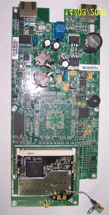
Click to zoom
Application Details
- Equipment Class
- DTS - Digital Transmission System
- Date of Grant
- Jun 05, 2007
- Application Purpose
- Original Equipment
- Date of Application
- Jun 04, 2007
- Equipment Note
- ODU
- Frequency Range
- 2412.00000000 - 2462.00000000
- Company
- Radwin Ltd.
- Country
- Israel
Documents & Files
Document Text
Text extracted from the exhibit documents filed with the FCC. Open a document above to read the original.
Users Manual
Installation and Operation Manual WinLink™1000 Point-to-Point Wireless Product Family Version 11.1 WinLink 1000 Point-to-Point Wireless TDM/IP Installation and Operation Manual Notice This manual contains information that is proprietary to RADWIN Ltd. ("RADWIN"). No part of this publication may be reproduced in any form whatsoever without prior written approval by RADWIN Ltd. Right, title and interest, all information, copyrights, patents, know-how, trade secrets and other intellectual property or other proprietary rights relating to this manual and to the WinLink 1000 and any software components contained therein are proprietary products of RADWIN protected under international copyright law and shall be and remain solely with RADWIN. WinLink 1000 is a registered trademark of RADWIN. No right, license, or interest to such trademark is granted hereunder, and you agree that no such right, license, or interest shall be asserted by you with respect to such trademark. You shall not copy, reverse compile or reverse assemble all or any portion of the Manual or the WinLink 1000. You are prohibited from, and shall not, directly or indirectly, develop, market, distribute, license, or sell any product that supports substantially similar functionality as the WinLink 1000 based on or derived in any way from the WinLink 1000. Your undertaking in this paragraph shall survive the termination of this Agreement. This Agreement is effective upon your opening of the WinLink 1000 package and shall continue until terminated. RADWIN may terminate this Agreement upon the breach by you of any term hereof. Upon such termination by RADWIN, you agree to return to RADWIN the WinLink 1000 and all copies and portions thereof. For further information contact RADWIN at the address below or contact your local distributor. International Headquarters RADWIN Ltd. U.S. Headquarters RADWIN Inc. 27 Habarzel Street 900 Corporate Drive Tel Aviv 69710 Israel Mahwah, NJ 07430 USA Tel: 972-54-766-00-44 Tel: 1.800.444.7234 (ext. 341) Fax: 972-3-7662918 Fax: (201) 529-5777 E-mail: [email protected] E-mail: [email protected] FCC – User Information This equipment has been tested and found to comply with the limits for a Class B digital device, pursuant to Part 15 of the FCC Rules. These limits are designed to provide reasonable protection against harmful interference in a residential installation. This equipment generates, uses and can radiate radio frequency energy and, if not installed and used in accordance with the instructions, may cause harmful interference to radio communications. However, there is no guarantee that interference will not occur in a particular installation. If this equipment does cause harmful interference to radio or television reception, which can be determined by turning the equipment off and on, the user is encouraged to try to correct the interference by one or more of the following measures: -- Reorient or relocate the receiving antenna. -- Increase the separation between the equipment and receiver. -- Connect the equipment into an outlet on a circuit different from that to which the receiver is connected. Consult the dealer or an experienced radio/TV technician for help. Changes or modifications to this equipment not expressly approved by the party responsible for compliance (RADWIN) could void the user’s authority to operate the equipment. It is the responsibility of the installer to ensure that when using the Warning outdoor antenna kits in the United States (or where FCC rules apply), only those antennas certified with the product are used. The use of any antenna other than those certified with the product is expressly forbidden in accordance to FCC rules CFR47 part 15.204. Outdoor units and antennas should be installed ONLY by experienced installation professionals who are familiar with local building and safety codes and, wherever applicable, are licensed by the appropriate Warning government regulatory authorities. Failure to do so may void the WinLink-1000 warranty and may expose the end user or the service provider to legal and financial liabilities. RADWIN and its resellers or distributors are not liable for injury, damage or violation of regulations associated with the installation of outdoor units or antennas. FCC Notation for Indoor Units IDU-E and IDU-C Concerning all models and configurations This device complies with part 15 of the FCC Rules. Operation is subject to the following two conditions: (1) This device may not cause harmful interference, and (2) this device must accept any interference received, including interference that may cause undesired operation. Quick Start Guide Installation of WinLink 1000 should be carried out only by a qualified technician. If you are familiar with WinLink 1000, use this guide to prepare the units for operation. If you are not familiar with WinLink 1000, please read the Installation and operation Manual carefully. 1. Equipment Required The following is a list of equipment required for installing a WinLink 1000 link: • RJ-45 crimp tool (if pre-assembled cable is not used) • Drill (for wall mounting only) • IDU and ODU grounding cables • 13 mm (½′′) spanner/wrench • ODU to IDU cable if not ordered (outdoor class, CAT-5e, 4 twisted pairs) • Cable ties • Laptop running Windows 2000 or Windows XP. 2. Before the Installation 1. Verify that all equipment and tools are available. 2. Install the WinLink 1000 software on the laptop; the installation takes several minutes. The software installation leaves the WinLink 1000 Manager icon on the desktop. 3. BRS systems only - Activate the link. WinLink 1000 Before the Installation 1 Quick Start Guide Installation and Operation Manual 3. Installing the WinLink 1000 Units Æ To install the ODU: 1. At site A, route the ODU cable from the ODU location (on the roof) to the IDU location (inside the building). The maximum length is 100m. 2. Mount the ODU unit to the mast or wall, using the mounting kit and mounting instr…
Text truncated - open the document above for the full version.
Users Manual
Chapter 5 Diagnostics and Troubleshooting This chapter describes the WinLink 1000 diagnostic functions, which include: • Get Link Information • Monitoring Performance • Error detection and alarms including Link Compatibility • Diagnostic tests (local and remote loopbacks on E1 or T1 link) • Troubleshooting • Frequently asked questions. 5.1 Automatic Link Data Collection (Get Link Information) The Get Link Information feature collects all the link and Manager information which can be used for diagnostics. In the event of needing to contact technical support please send this file so as to speed up the assistance. Æ To get link information 1. Click Help on the menu bar, select Link Information. The Get Link Information dialog box appears. See Figure 5-1. 2. Select or deselect the data options. If the file is to be sent to Technical Support leave all options checked. 3. Click File Path to get to the directory to save the file in. 4. Click Start to save the information. The file is saved as Link Information.txt Automatic Link Data Collection (Get Link Information) 5-1 Chapter 5 Diagnostics and Troubleshooting WinLink 1000 Installation and Operation Manual Figure 5-1. Get Link Information 5.2 Monitoring Performance WinLink 1000 constantly monitors traffic over the radio link and collects the following statistics data: • Site 1/Site 2 received traffic rate (in Mbps) • Site 1/Site 2 received frames rate (in Mbps) • Radio signal strength (in dBm) • Error (Blocks). The statistics (monitor) log and event log can be saved as TXT files. New alarms are automatically added to the text file, as they enter the event log. Saving the Monitor Log Æ To save the monitor log: 1. From the Tools menu, choose Preferences. The Preferences dialog box appears (see Figure 5-2). 2. Click the Monitor Tab. 3. Select the file to save. 5-2 Monitoring Performance WinLink 1000 Installation and Operation Manual Chapter 5 Diagnostics and Troubleshooting 4. Click the check box to open the file for saving. 5. Click the button and in the Select File dialog box indicate in which folder and under what name the alarm log file is to be saved. 6. Set the time interval for adding data to the file. 7. Click OK to save the file Figure 5-2. Preferences Dialog Box, Monitor Tab Setting the Events Preferences You can define a color that the traps are displayed in the monitor pane, according to severity of the event. The severity is predefined. Æ To set the trap color: 1. From the Tools menu, choose Preferences. The Preferences dialog box appears). 2. Click the Events Tab (see Figure 5-3). 3. Select the Event priority type and click on the button. A color chart opens. Monitoring Performance 5-3 Chapter 5 Diagnostics and Troubleshooting WinLink 1000 Installation and Operation Manual 4. Select the desired color. 5. Repeat for all the trap types. Æ To set the trap background color: • Click Background Color to change the text background. Æ To reset the trap colors: • Click Reset Settings to return to the default color settings. Saving the Events Log Æ To save the event log: 1. From the Tools menu, choose Preferences. The Preferences dialog box appears (see Figure 5-3). 2. Click the Events Tab. 3. Select the file to save. 4. Click the check box to open the file for saving. 5. Click the button and in the Select File dialog box indicate in which folder and under what name the alarm log file is to be saved, and click OK. 5-4 Monitoring Performance WinLink 1000 Installation and Operation Manual Chapter 5 Diagnostics and Troubleshooting Figure 5-3. Preferences Dialog Box, Event Log Tab Monitoring Performance 5-5 Chapter 5 Diagnostics and Troubleshooting WinLink 1000 Installation and Operation Manual 5.3 Viewing Performance Reports The Performance Monitor Report displays performance views of each of the interfaces 1 (see Figure 5-4). Several performance data are collected for each of the interfaces (ES, SES, and UAS), as well as Specific data per Interface type (e.g., TX and RX bytes for Ethernet). For the Air Interface, user defined thresholds data are collected. Refer to Table 5-1 and Table 5-2. Data is collected and selectively displayed based on three time intervals as selected by the Interval radio buttons: • Current (t=0) • 15 minutes Intervals • Daily. UAS – This parameter counts the time the air link was not providing any service. There are several potential reasons for this situation; one of the sites has a power failure, high interference, maintenance operation etc. Radio BBER Threshold – This parameter counts the seconds in which the radio performance is below a user specified threshold. The threshold is measured in percent. The threshold can be set from 0.1% up to 50%. For links with E1/T1 service the recommended value is 1% (system default). Excellent TDM service is expected below the 1% threshold, meaning that for 1% threshold, the expected BBER value should be 0 if there are no problems during the 15 min interval. If the BBER threshold increases some degraded service might be noticed. For links with Ethernet only service, 8% threshold is recommended and not 1% meaning that for 8% threshold, the recommended BBER value should be 0 if there are no problems during the 15 min interval. Since WinLink 1000 provides a loss less Ethernet service, there is throughput degradation in case of interference. The degradation is proportional to the BBER. Radio RSS Threshold can also be used to indicate problems in the radio channel. After verifying the RSS according to the link budget calculator 1 Ethernet performance is not collected in PoE systems. 5-6 Viewing Performance Reports WinLink 1000 Installation and Operation Manual Chapter 5 Diagnostics and Troubleshooting during the installation. A value of -5dB from the current RSS is recommended as a threshold. Figure 5-4. Performance Monitoring Report window Viewing Performance Reports 5-7 Chapter 5 Diagnostics and Troubleshooting WinLink 1000 Installation and Operation Manual Table 5-1. Explanation of p…
Text truncated - open the document above for the full version.
Block Diagram
Radwin Ltd. FCC ID:Q3KAMWL1240H Date: February 2007 Block_diagram_17421_revisedID_rev1.doc Page 1 of 2 BLOCK DIAGRAM of WinLink 1000/F24/HE Rev1
Cover Letter(s)
RADWIN Ltd. 32 Habarzel St Tel-Aviv, 69710, Israel, Tel- 972-3-766-2901, Fax-972-3-766-2902 February 22, 2007 American TCB 6731 Whittier Ave Suite C110 McLean, VA 22101 USA Subject: Request for conf identiality, FCC ID:Q3KAMWL1240H Dear Gentlemen, In regards the exhibits submitted in support of the application for FCC ID: Q3KAMWL1240H, please classify the following as confidential under the provision of 47 CFR 0.459: 1) schematic diagram, file “Schematic_diagram_17421” (2 pages) of this Application. These exhibits contain technical information which Radwin Ltd. deems to be sensitive and proprietary. Therefore this information cannot be published. If this information were to be made public it could be used to the disadvantage of the applicant in the marketplace. Sincerely yours, Itai Rubinstein Engineering department manager Radwin Ltd
Cover Letter(s)
April 30, 2007 To Whom It May Concern: RADWIN ensures that the device FCC ID: Q3KAMWL1240H is limited to professional installation, by the following: 1. Marketing The device is not sold retail to the general public or by mail order. RADWIN sells the device only to its carefully selected certified distributors. 2. Professional installation The device must be installed and controlled by specially trained professionals. RADWIN provides all its distributors with training seminars which focus on installation and maintenance and officially certifies personnel who pass RADWIN training to perform installation and maintenance. The installation requires knowledge in radio equipment handling and technical knowledge concerned with operation of RADWIN's device. Installation guidelines must be followed to ensure proper operation of the device. 3. Application The intended use is generally not for the general public. It is generally for industry/commercial use. RADWIN's end-users include cellular and fixed carriers, telecom/internet service providers and IT departments of utility companies and enterprises. Itai Rubinstein Head of Engineering Dpt. , RADWIN Ltd.
Cover Letter(s)
American Telecommunications Certification Body Inc. 6731 Whittier Ave, McLean, VA 22101 April 12, 2007 RE: Radwin Ltd. FCC ID: Q3KAMWL1240 After a review of the submitted information, I have a few comments on the above referenced Application. Depending on your responses, kindly understand there may be additional comments. 1) The internal photographs may not normally be held confidential strictly on the basis of trade secrets. This typically requires a stronger justification as to why the end user would never be able to see the internal components (i.e. device is potted, etc.). It should be explained how the user would never expect to be able to simply open the device. Please remove this justification from the letter of confidentiality or provide a better justification. As an alternative, you may use a black marker to "black out" the top of any readable components and provide new internal RF photographs. Please let us know how you wish to proceed with this issue. 2) Block Diagram appears to show the device is capable of both 5 GHz and 2.4 GHz. However the application does not support this. How is this device in compliance with 15.15 for 5 GHz. 3) Operational description appears to show the device is capable of 4.9, 5 GHz and 2.4 GHz. However the application does not support this. How is this device in compliance with 15.15 for 4.9 & 5 GHz. 4) Users Manual appears to show the device is capable of 4.9, 5 GHz and 2.4 GHz. Given the internal RF card appears to operate be capable of operation on these frequencies, how is this device in compliance with 15.15 for 4.9 and 5 GHz. 5) Operational Description for integrated antenna shows both 17 and 15.2 dBi gain antenna – however this application does not appear to support a 17 dBi antenna. Please review. 6) This device appears to incorporate a standard N antenna connection. To meet the requirements of 15.203 using a standard connector, this device must be limited to Professional Installation only. This requires a cover letter requesting and justifying how the applicant ensures professional installation to be provided. The letter should address the following 3 items: a) Marketing example: The device cannot be sold retail, to the general public or by mail order. It must be sold to dealers or have strict marketing control. b) Requires professional installation; examples: - installation must be controlled. - installed by licensed professionals ( EUT sold to dealer who hire installers) - installation requires special training ( special programming, access to keypad, field strength measurements made) What is unique, sophisticated, complex, or specialized about your equipment which REQUIRES it to be installed by a professional installer? c) Application example: -The intended use is generally not for the general public. It is generally for industry/commercial use. z Page 2 April 13, 2007 7) Test photographs for AC powerline conducted photographs appear to show the device unterminated. Note that either the antenna or appropriate termination should have been utilized. Please review. 8) Page 113 of the users manual suggest the user can use any antenna they desire with the device. This is not the case (see FCC Part 15.203/15.204) and only certain approved antennas can be used. Please review. 9) Please explain compliance to 15.15 for the 24 dBi gain antenna. I.E. What keeps the end user from being able to adjust the output power above 250 mW through the user interface if the 24 dBi gain antenna is installed with the unit? 10) Plots do not fully support the method specified by 7.2 (i.e. RBW > 6 dB). Please review DTS test guidance as well. 11) Should plot 7.4.11 include an additional note as well? 12) Peak to average plots appear odd. Average measurements appear flat and do not appear to shown any emissions. Normally this implies that a duty cycle was present and therefore a VBW > 10 Hz may be necessary. (i.e. plots on pages 111 – 116). Additionally, it is uncertain why emissions on these pages for peak are as high as they are given earlier pages (pages 85 – 110 do not appear to show any significant readings. Please review/explain/etc. See difference between 15.2 and 24 dBi results and comparison between peak and average. 13) Please explain the high readings noted on plots 7.5.7 – 7.5.9. 14) It is uncertain why emissions on these pages for peak are as high as they are given earlier pages (pages 128 - 154 do not appear to show any significant readings while the results on pages 155 – 160 do. Please review/explain/etc. Timothy R. Johnson Examining Engineer mailto: [email protected] The items indicated above must be submitted before processing can continue on the above referenced application. Failure to provide the requested information may result in application termination. Correspondence should be considered part of the permanent submission and may be viewed from the Internet after a Grant of Equipment Authorization is issued. Please do not respond to this correspondence using the email reply button. In order for your response to be processed expeditiously, you must submit your documents through the AmericanTCB.com website. Also, please note that partial responses increase processing time and should not be submitted. Any questions about the content of this correspondence should be directed to the sender.
Cover Letter(s)
American Telecommunications Certification Body Inc. 6731 Whittier Ave, McLean, VA 22101 May 21, 2007 RE: Radwin Ltd. FCC ID: Q3KAMWL1240H After a review of the submitted information, I have a few comments on the above referenced Application. Depending on your responses, kindly understand there may be additional comments. 1) The block diagram appears to shown different chipsets than used in this device (which also shows 5 and 2.4 GHz). Please correct. 2) The response to item 9 is not detailed enough to understand if the device is fully compliant to requirements of 15.15. For instance, does the user have the ability to select product type in software? Even if the user selects the antenna used and this affects power, then compliance to 15.15 is not assured. There must be some means to set power that is not adjustable to the en user directly or indirectly once installed. Please explain. 3) FYI....Your power method has some slight variance. In the future regarding power measurement, please take care to utilize the FCC’s settings which cites: Method #3: · Set span to encompass the entire emission bandwidth (EBW) of the signal. · Set sweep trigger to “free run”. · Set RBW = 1 MHz. Set VBW ³ 1/T · Use linear display mode. · Use sample detector mode if bin width (i.e., span/number of points in spectrum) < 0.5 RBW. Otherwise use peak detector mode. · Set max hold. · Allow max hold to run for 60 seconds. · Compute power by integrating the spectrum across the 26 dB EBW or apply a bandwidth correction factor of 10 log (EBW/1 MHz) to the spectral peak of the emission. The integration can be performed using the spectrum analyzer’s band power measurement function with band limits set equal to the EBW band edges or by summing power levels in each 1 MHz band in linear power terms. The 1 MHz band power levels to be summed can be obtained by averaging, in linear power terms, power levels in each frequency bin across the 1 MHz. Timothy R. Johnson Examining Engineer mailto: [email protected] The items indicated above must be submitted before processing can continue on the above referenced application. Failure to provide the requested information may result in application termination. Correspondence should be considered part of the permanent submission and may be viewed from the Internet after a Grant of Equipment Authorization is issued. z Page 2 May 24, 2007 Please do not respond to this correspondence using the email reply button. In order for your response to be processed expeditiously, you must submit your documents through the AmericanTCB.com website. Also, please note that partial responses increase processing time and should not be submitted. Any questions about the content of this correspondence should be directed to the sender.
Cover Letter(s)
HERM O N LA BO RA TO RIES May 3, 2007 American TCB 6731 Whittier Ave Suite C110 McLean, VA 22101 Attn: Mr. Timothy R. Johnson, Examining Engineer RE: your e-mail dated April 13, 2007; Radwin Ltd. FCC ID: Q3KAMWL1240, ATCB004671 Revised ID: FCC ID:Q3KAMWL1240H Dear Mr. Johnson, Please find below the answers to your questions. 1) The revised files “Internal_photos_17421_revisedID” and “Internal_photos_RFcard_17421_revisedID” without black squares and without request for confidentiality were uploaded on May 3, 2007 via Internal Photos folder. A revised confidentiality letter “Confidentiality_letter_revisedID” was uploaded on May 3, 2007 via Additional Information folder. 2) The internal RF card is purchased by Radwin, so its operation was not explained in the block diagram. The data sheet for RF module operating in 2412-2462 MHz range, used in WinLink 1000/F24/HE system, file “RF_module_datasheet_17421_revisedID” was uploaded May 3, 2007 via Block Diagram folder. 3) The operational description is issued by Radwin as common data sheet for all WinLink 1000 products family, please refer only to the 2.4 GHz frequency band (the RF module used in WinLink 1000/F24/HE system operates in 2412-2462 MHz range). 4) The User Manual provides information of all WinLink1000 products family. Please refer only to the 2.4 GHz FCC radio band. 5) Operational description was corrected, file “Operational_description_17421_revisedID” was uploaded on May 3, 2007. 6) File “Professional_Installation_letter_17421_revisedID” was uploaded on May 3, 2007 via Additional Information folder. 7) The device was terminated during CE test. The enlarged photo added. The file “Setup_photos_17421_revisedID” was uploaded on May 3, 2007. 8) Please refer to page 5-20, last question, of the revised file “User_manual_17421_part2_revisedID”. 9) The software interface limits the transmission power to the maximum value determined by the product type. 10) The following test procedure was used. The rate VBW/resolution bandwidth of spectrum analyzer was set to 10 (3 MHz/300 kHz). The integration was performed using the spectrum analyzer’s band power measurement function with band limits set equal to the EBW band edges. The maximum peak output power was computed by integrating the spectrum across the 6 dB entire bandwidth of the EUT. The test report section 7.2 was revised. The corrected test report RADRAD_FCC.17421_rev2 was uploaded on May 3, 2007. 11) An additional note was included into corrected test report RADRAD_FCC.17421_rev2. HERM O N LA BO RA TO RIES 12) Measurement results (plots) provided on pages 111-116 and 85-110 were taken with the different measurement set up. Pages 111-116 demonstrate radiated emission found out during maximization with antenna height and turn table azimuth. Signal to noise ratio is better on these plots due to narrow span and use of high gain LNAs. Pages 85-110 demonstrate the relatively wide portions of spectrum which cannot be taken with high gain LNAs due to overloads. That is why the noise floor is higher on these plots. Actually the results measured with marker should be compared. The duty cycle was set to 100% during the tests. 13) An additional note below plots 7.5.7 – 7.5.9 was included into corrected test report RADRAD_FCC.17421_rev2. This emission originates from the external auxiliary equipment which powers the EUT. We have discovered this later on during the final measurements at the OATS and applied better filtering of DC voltage from external auxiliary equipment to the EUT. The Table 7.5.4 was corrected for 3 m distance test results. 14) Measurement results (plots) provide on pages 128-154 and 155-160 were taken with the different measurement set up. Pages 155-160 demonstrate radiated emission found out during maximization with antenna height and turn table azimuth. Signal to noise ratio is better on these plots due to narrow span and use of high gain LNAs. Pages 128-154 demonstrate the relatively wide portions of spectrum which cannot be taken with high gain LNAs due to overloads. That is why the noise floor is higher on these plots. Actually the results measured with marker should be compared. 15) Additionally the documents with revised ID (cover letter, ATCB Form 731, Label location, external photos, RF_evaluation) were uploaded on May 3, 2007 via appropriate folders. Sincerely, Marina Cherniavsky, certification engineer Hermon Laboratories
Cover Letter(s)
HERM O N LA BO RA TO RIES May 28, 2007 American TCB 6731 Whittier Ave Suite C110 McLean, VA 22101 Attn: Mr. Timothy R. Johnson, Examining Engineer RE: your e-mail dated May 21, 2007; Radwin Ltd. FCC ID:Q3KAMWL1240H, ATCB004671 Dear Mr. Johnson, Please find below the answers to your questions. 1) The new file “Block_diagram_17421_revisedID_rev1” was uploaded on May 28, 2007. 2) The applicant does confirm: The product is released from the factory as a defined product type. The product type defines the maximum transmission power available to the user. The user has no option to alter the product type or exceed the maximum transmission power determined by the product type. Sincerely, Marina Cherniavsky, certification engineer Hermon Laboratories
External Photos
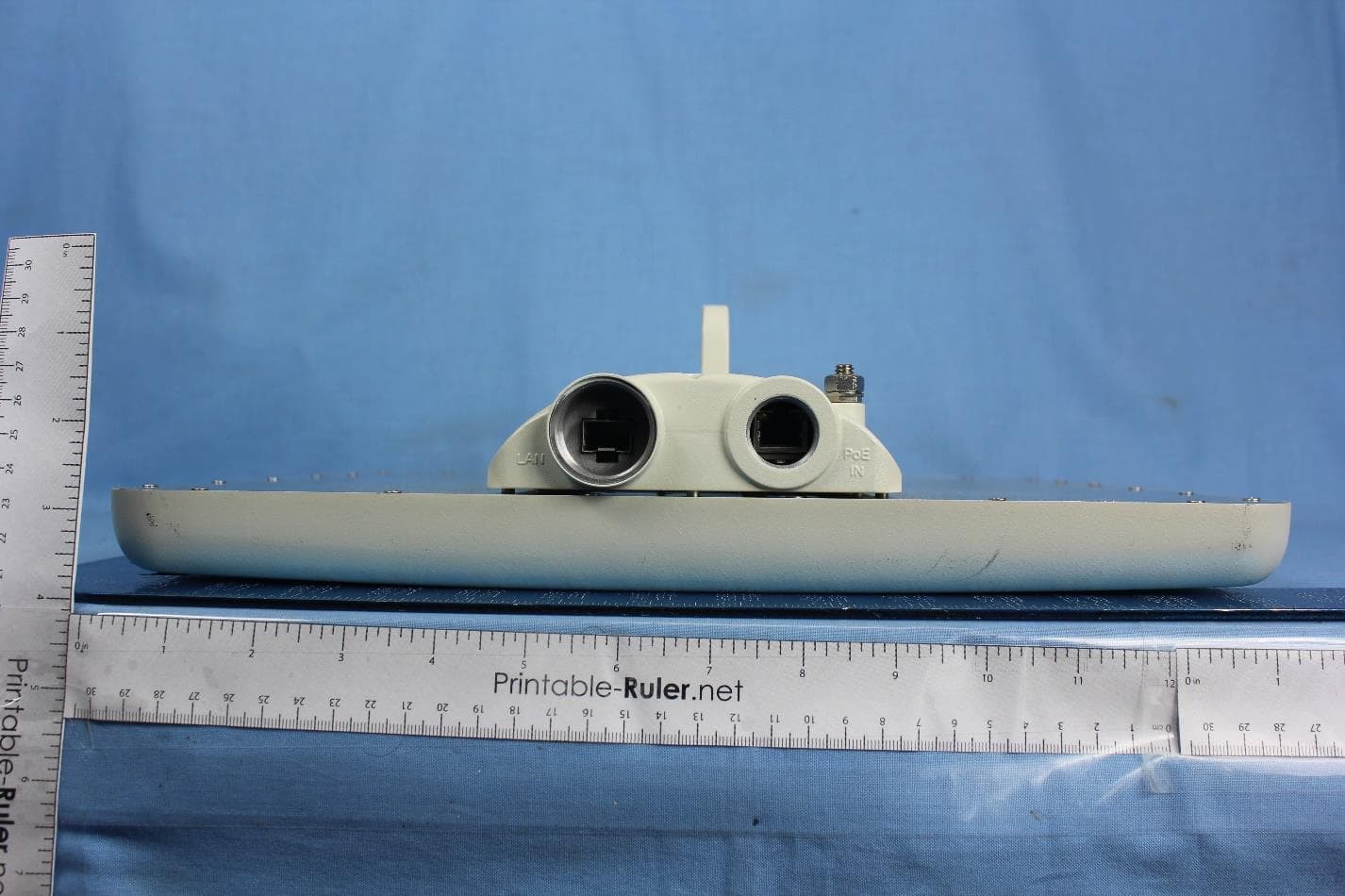
Radwin Ltd. FCC ID:Q3KAMWL1240H Date: February 2007 Page 1 of 3 EXTERNAL PHOTOGRAPHS This document contains 2 photographs Radwin Ltd. FCC ID:Q3KAMWL1240H Date: February 2007 Page 2 of 3 Photograph No.1 WinLink 1000/F24/HE front view Radwin Ltd. FCC ID:Q3KAMWL1240H Date: February 2007 Page 3 of 3 Photograph No.2 WinLink 1000/F24/HE rear side view
ID Label/Location Info
FCC ID:Q3KAMWL1240H Date:February 2007 Page 1 of 3 Label with FCC ID:Q3KAMWL1240H for ODU unit Label with FCC logo for IDU unit FCC ID:Q3KAMWL1240H Date:February 2007 Page 2 of 3 An ODU terminal shall bear the label with FCC ID:Q3KAMWL1240H and RADWIN logo on a back panel as shown in the photo below: FCC ID:Q3KAMWL1240H FCC ID:Q3KAMWL1240H Date:February 2007 Page 3 of 3 The statement according to FCC part 15 section 15.19 is affixed to indoor unit, connected by wires to ODU and marketed together. Winlink1000 Radwin Ltd.
Internal Photos
Radwin Ltd. FCC ID:Q3KAMWL1240H Date: February 2007 Internal_photos_RFcard_17421_revisedID.doc Page 1 of 6 INTERNAL PHOTOGRAPHS of RF card This document contains 5 photographs Radwin Ltd. FCC ID:Q3KAMWL1240H Date: February 2007 Internal_photos_RFcard_17421_revisedID.doc Page 2 of 6 Photograph No.1 RF card front view Radwin Ltd. FCC ID:Q3KAMWL1240H Date: February 2007 Internal_photos_RFcard_17421_revisedID.doc Page 3 of 6 Photograph No. 2 RF card with shield removed Radwin Ltd. FCC ID:Q3KAMWL1240H Date: February 2007 Internal_photos_RFcard_17421_revisedID.doc Page 4 of 6 Photograph No.3 RF card components underneath shield Radwin Ltd. FCC ID:Q3KAMWL1240H Date: February 2007 Internal_photos_RFcard_17421_revisedID.doc Page 5 of 6 Photograph No.4 RF card second side view Radwin Ltd. FCC ID:Q3KAMWL1240H Date: February 2007 Internal_photos_RFcard_17421_revisedID.doc Page 6 of 6 Photograph No.5 RF card without shield view
Internal Photos
Radwin Ltd. FCC ID:Q3KAMWL1240H Date: February 2007 Internal_photos_17421_revisedID.doc Page 1 of 6 INTERNAL PHOTOGRAPHS This document contains 5 photographs Radwin Ltd. FCC ID:Q3KAMWL1240H Date: February 2007 Internal_photos_17421_revisedID.doc Page 2 of 6 Photograph No.1 WinLink 1000/F24/HE internal view Radwin Ltd. FCC ID:Q3KAMWL1240H Date: February 2007 Internal_photos_17421_revisedID.doc Page 3 of 6 Photograph No.2 WinLink 1000/F24/HE internal view without cover Radwin Ltd. FCC ID:Q3KAMWL1240H Date: February 2007 Internal_photos_17421_revisedID.doc Page 4 of 6 Photograph No.3 WinLink 1000/F24/HE main PCB front view Radwin Ltd. FCC ID:Q3KAMWL1240H Date: February 2007 Internal_photos_17421_revisedID.doc Page 5 of 6 Photograph No.4 WinLink 1000/F24/HE main PCB s…
Text truncated - open the document above for the full version.
Contact Information
Applicant
Shlomo Weiss(Standardization Officer)
Technical Contact
Hermon LaboratoriesAlex Usoskin
[email protected]972-4628-8001
Harakevet Industrial zone · Binyamina · Israel
Non-Technical Contact
Radwin Ltd.Itai Rubinstein
[email protected]972 3766 2928
Test Firm
Hermon Laboratories Ltd.Alexander Usoskin
Technical Specifications
| # | Rule Parts | Frequency Range | Power Output |
|---|---|---|---|
| 1 | 15C | 2.41 GHz - 2.46 GHz | 471.00 mW |
Other Applications from Radwin Ltd.
Q3K-PTP5GAX
Feb 25, 20235 GHz High Performance PtP Outdoor Unit
Equipment Class
NII - Unlicensed National Information Infrastructure TX
Q3K-NEO5X
Apr 27, 2021Single Carrier 5.x GHz Base Station with Beamforming Antenna, Dual Carrier 5.x GHz Base Station with Beamforming Antenna
Equipment Class
NII - Unlicensed National Information Infrastructure TX
Q3K-5XSUALMOD
Apr 13, 20215 GHz SU/Alpha Board
Equipment Class
NII - Unlicensed National Information Infrastructure TX
Q3K-5XACMODMS
Sep 13, 20205 GHz MS RF Module
Equipment Class
NII - Unlicensed National Information Infrastructure TX
Q3K-TRBR600G
Aug 25, 2020Point to point/point to multipoint 57-71 GHz radio transceiver
Equipment Class
DXX - Part 15 Low Power Communication Device Transmitter