Q3KAMWL1580Point to Point Broadband Radio System
Radwin Ltd.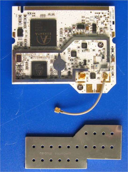
Click to zoom
Application Details
- Equipment Class
- DTS - Digital Transmission System
- Date of Grant
- Oct 23, 2006
- Application Purpose
- Original Equipment
- Date of Application
- Oct 22, 2006
- Equipment Note
- Point to Point Broadband Radio System
- Frequency Range
- 5740.00000000 - 5835.00000000
- Company
- Radwin Ltd.
- Country
- Israel
Documents & Files
Document Text
Text extracted from the exhibit documents filed with the FCC. Open a document above to read the original.
Users Manual
Installation and Operation Manual WinLink™1000 Point-to-Point Wireless Product Family Revision 8.22 WinLink1000 Point-to-Point Wireless TDM/IP Revision 8.0 Installation and Operation Manual Notice This manual contains information that is proprietary to RADWin Ltd. ("RADWIN"). No part of this publication may be reproduced in any form whatsoever without prior written approval by RADWIN Ltd. Right, title and interest, all information, copyrights, patents, know-how, trade secrets and other intellectual property or other proprietary rights relating to this manual and to the WinLink1000 and any software components contained therein are proprietary products of RADWIN protected under international copyright law and shall be and remain solely with RADWIN. WinLink1000 is a registered trademark of RADWIN. No right, license, or interest to such trademark is granted hereunder, and you agree that no such right, license, or interest shall be asserted by you with respect to such trademark. You shall not copy, reverse compile or reverse assemble all or any portion of the Manual or the WinLink1000. You are prohibited from, and shall not, directly or indirectly, develop, market, distribute, license, or sell any product that supports substantially similar functionality as the WinLink1000 based on or derived in any way from the WinLink1000. Your undertaking in this paragraph shall survive the termination of this Agreement. This Agreement is effective upon your opening of the WinLink1000 package and shall continue until terminated. RADWIN may terminate this Agreement upon the breach by you of any term hereof. Upon such termination by RADWIN, you agree to return to RADWIN the WinLink1000 and all copies and portions thereof. For further information contact RADWIN at the address below or contact your local distributor. International Headquarters RADWIN Ltd. 32 Habarzel Street Tel Aviv 69710 Israel Tel: 972-54-766-00-44 Fax: 972-3-7662918 E-mail: [email protected] U.S. Headquarters RADWIN Inc. 900 Corporate Drive Mahwah, NJ 07430 USA Tel: 1.800.444.7234 (ext. 341) Fax: (201) 529-5777 E-mail: [email protected] FCC-15 User Information This equipment has been tested and found to comply with the limits for a Class B digital device, pursuant to Part 15 of the FCC Rules. These limits are designed to provide reasonable protection against harmful interference in a residential installation. This equipment generates, uses and can radiate radio frequency energy and, if not installed and used in accordance with the instructions, may cause harmful interference to radio communications. However, there is no guarantee that interference will not occur in a particular installation. If this equipment does cause harmful interference to radio or television reception, which can be determined by turning the equipment off and on, the user is encouraged to try to correct the interference by one or more of the following measures: -- Reorient or relocate the receiving antenna. -- Increase the separation between the equipment and receiver. -- Connect the equipment into an outlet on a circuit different from that to which the receiver is connected. Consult the dealer or an experienced radio/TV technician for help. Changes or modifications to this equipment not expressly approved by the party responsible for compliance (RADWIN) could void the user’s authority to operate the equipment. It is the responsibility of the installer to ensure that when using the outdoor antenna kits in the United States (or where FCC rules apply), only those antennas certified with the product are used. The use of any antenna other than those certified with the product is expressly forbidden in accordance to FCC rules CFR47 part 15.204. Warning Outdoor units and antennas should be installed ONLY by experienced Warning installation professionals who are familiar with local building and safety codes and, wherever applicable, are licensed by the appropriate government regulatory authorities. Failure to do so may void the WinLink-1000 warranty and may expose the end user or the service provider to legal and financial liabilities. RADWIN and its resellers or distributors are not liable for injury, damage or violation of regulations associated with the installation of outdoor units or antennas. This device complies with part 15 of the FCC Rules. Operation is subject to the following two conditions: (1) This device may not cause harmful interference, and (2) this device must accept any interference received, including interference that may cause undesired operation. Installing WinLink 1000 Units 1 Quick Start Guide Installation of WinLink 1000 should be carried out only by a qualified technician. If you are familiar with WinLink 1000, use this guide to prepare the units for operation. 1. Installing WinLink 1000 Units ODU Package Contents: • ODU • Mast/Wall mounting kit • WinLink 1000 Management software installation CD • Mounting instructions • Spare RJ-45 connector • ODU to IDU cable at length ordered (optional) IDU-E Package Contents: • IDU-E • 110V/240V adaptor • IDU wall-mounting drilling template • Spare RJ-45 connector (Optional) IDU-C or AIND Package Contents: • IDU-C or AIND • For IDU-C AC model, 110v/240 VAC with 3-prong connector cable • For DC model, -48 VDC with 3-pin terminal block connector (green) • IDU standard 1-U, 19” carrier rack • Spare RJ-45 connector Equipment Required: • RJ-45 crimp tool (If pre-assembled cable is not used) Quick Start Guide WinLink 1000 Installation and Operation Manual 2 Installing WinLink 1000 Units • Drill (for wall mounting only) • IDU and ODU grounding cable • 13 mm or 1/2′′ socket spanner • ODU to IDU cable if not ordered (Outdoor class, CAT-5e, 4 twisted pairs) • Cable ties • Laptop running Windows 2000 or Windows XP Before the installation 1. Install the WinLink 1000 software on the laptop. 2. Verify that all equipment and tools are available. Performing Installation Î To install the ODU: 1. At site A, route the ODU cab…
Text truncated - open the document above for the full version.
Users Manual
WinLink1000 Installation and Operation Manual Chapter 4 Configuration Figure 4-8. Configuration Dialog Box 3. Select the appropriate item in the left hand list to open a dialog box. 4. Click Apply to save the changes. 4.5 Setting the Clock Configuration The TDM clock feature is enabled in all carrier class IDU’s in addition to new hardware IDU’s. A TDM dialog box will appear where IDU supports the clocking configuration feature (see Figure 4-9 and Figure 4-10). A new master clock configuration option is available in the Link Configuration Wizard. The automatic mode selects the clock from the first trunk that is working in normal mode (or is configured to loop- back maintenance). If a specific trunk is selected, this trunk shall be Setting the Clock Configuration 4-13 Chapter 4 Configuration WinLink1000 Installation and Operation Manual used as the system master regardless of the trunks state. The current master clock trunk is also displayed. Figure 4-9. TDM clock dialog box for T1 IDU 4-14 Setting the Clock Configuration WinLink1000 Installation and Operation Manual Chapter 4 Configuration Figure 4-10. TDM clock dialog box for E1 IDU If TDM services are selected then the TDM parameters dialog box appears. The TDM Parameters dialog box contains five working modes; select the appropriate clock mode according to your application. Choosing one of these modes sets the TDM clock behavior on both sides of the link. The user equipment must be configured as described Table 4-1. Table 4-1. TDM Clock Modes Unit clock mode User equipment side Local Unit Remote Unit HQ side Branch side 1 Transparent Transparent Internal/Recov er Internal/Recov er 2 Loop Time Recover Internal Recover 3 Recover Loop Time Recover Internal Setting the Clock Configuration 4-15 Chapter 4 Configuration WinLink1000 Installation and Operation Manual Unit clock mode User equipment side Local Unit Remote Unit HQ side Branch side 4 Internal Recover Recover Recover 5 Recover Internal Recover Recover 4-16 Setting the Clock Configuration WinLink1000 Installation and Operation Manual Chapter 4 Configuration Transparent/Transparent WinLink1000 transparently regenerates the clock from line clock side to Tx clock on the opposite side of the link. Loop time/Recover The local unit receive clock is the transmit clock on both sides of the link. Recover/Loop time The remote unit receive clock is the transmit clock on both sides. Internal/Recover The local unit internal oscillator generates the clock while the remote unit recovers this clock. Recover/Internal The remote unit internal oscillator generates the clock while the local unit recovers this clock. Note The Line code option is used with T1 Systems. a summary of the link configuration (see Figure 4-12). 4-17 Chapter 4 Configuration WinLink1000 Installation and Operation Manual Figure 4-12. Configuration Link, Finish screen 5. Click Finish to complete the configuration wizard. The Main screen is displayed. 4.7 Changing the Transmit Power Each site can have a different transmit power level. Æ To change the Transmit Power: 1. Click Configuration from the main menu. 2. Select which site to configure. The Configuration dialog box opens. 3. Select Air Interface. (See Figure 4-13) 4. Select the required Transmit Power Level. Table 4-2 shows the available power limits for each WinLink1000 system. 4-18 Changing the Transmit Power WinLink1000 Installation and Operation Manual Chapter 4 Configuration 5. Click Apply to save the changes. Figure 4-13. Changing the Transmit Power Changing the Transmit Power 4-19 Chapter 4 Configuration WinLink1000 Installation and Operation Manual Table 4-2. Typical Transmit Power Limits Regulation Version Min Tx [dB] Max Tx [dB] MaxTx at 36 Mbps [dB] MaxTx at 48 Mbps [dB] Power Control F58 4 16 14 10 Yes F58/EXT 4 16 14 10 Yes F49 14 15 15 14 No F53 -3 8 8 8 Yes F53/EXT 3 3 3 3 No F24 18 18 18 18 No FCC F53HP 10 16 14 10 Yes India F58CN -1 10 10 10 Yes China F24/EXT/ET SI -4 -4 -4 -4 No F54 2 8 8 8 Yes F54/ETSI 2 8 8 8 Yes ETSI F54- HG/EXT -3 3 3 3 Yes 4.8 Defining the Management Addresses Each site must be configured separately, first site A then site B. Æ To define the Management Addresses: 1. Click Configuration from the main menu. 2. Select which site to configure. The Configuration dialog box opens. 3. Select Management (see Figure 4-14). 4. Enter the IP address of the ODU in the IP address field. Note If performing configuation from the WinLink manager, the IP address is entered in the login screen ( r Figure 2-4) 4-20 Defining the Management Addresses WinLink1000 Installation and Operation Manual Chapter 4 Configuration 5. Enter the Subnet Mask. 6. Enter the Default Gateway. 7. Enter the Trap Destination. This is the IP address of the PC running the management application. The event log will be stored at this address. 8. Click Apply to save the changes. Figure 4-14. Configuration, Management Notes The Installation mode button opens the Link Installation wizard to reinstall the link. The Backup and Restore buttons are for saving and restoring the configuration files. Defining the Management Addresses 4-21 Chapter 4 Configuration WinLink1000 Installation and Operation Manual 4.9 Setting the Date and Time Æ To set Date and time The ODU maintains a date and time value. The date and time value should be synchronized with any Network Time Protocol (NTP) version 3 compatible server 1 . On power-up the ODU configures the initial date and time using an NTP server. If the server IP is not configured or is not reachable, a default time is set. When configuring the NTP server IP, you should also configure the offset from the Universal Coordinated Time (UTC). If there is no server available, you can either set the date and time, or you can set the manager workstation time. Note that manual setting is not recommended since reset, power up, or synchronization with an NTP server will override the setting. • The NTP uses UDP port 123. If a firewall is configured between the O…
Text truncated - open the document above for the full version.
Cover Letter(s)
RADWIN Ltd. 32 Habarzel St Tel-Aviv, 69710, Israel, Tel- 972-3-766-2901, Fax-972-3-766-2902 September 27, 2006 American TCB 6731 Whittier Ave Suite C110 McLean, VA 22101 USA Subject: Application for certification of a wireless point–to-point transmission system, FCC ID: Q3KAMWL1580 Dear Gentlemen, Please find attached our application for certification of a wireless point–to-point transmission system, model names 1) WinLink 1000-F58/HP (ODU), 2) WL1000-AIND/F58/FCC/EXT/4T1, 3) Airmux-200/AIND/F58/FCC/EXT/4T1 4) FibeAir-48-AIND-58-EX-AN-2FE-4T1 5) MRL-500- AIND/F58/FCC/EXT/4T1 FCC ID:Q3KAMWL1580, prepared in accordance with FCC Rules, part 15, sections 15.247, 15.207. The product testing and this application for certification were performed by Hermon Laboratories, which is listed by FCC, Registration Numbers 90623, 90624. Hermon Labs responsible person is Mr. Alex Usoskin, tel: 011 972 4628 8001, fax:011 972 4628 8277, e-mail:[email protected]. Please send an invoice to Hermon Labs. Sincerely yours, Itai Rubinstein Engineering department manager Radwin Ltd
Cover Letter(s)
RADWIN Ltd. 32 Habarzel St Tel-Aviv, 69710, Israel, Tel- 972-3-766-2901, Fax-972-3-766-2902 September 27, 2006 American TCB 6731 Whittier Ave Suite C110 McLean, VA 22101 USA Subject: Request for confidentiality, FCC ID:Q3KAMWL1580 Dear Gentlemen, In regards the exhibits submitted in support of the application for FCC ID: Q3KAMWL1580, please classify the following as confidential under the provision of 47 CFR 0.459: 1) schematic diagram, file “Schematic_diagram_17204” (2 pages) of this Application. This exhibit contains technical information which Radwin Ltd. deems to be sensitive and proprietary. Therefore this information cannot be published. If this information were to be made public it could be used to the disadvantage of the applicant in the marketplace. Sincerely yours, Itai Rubinstein Engineering department manager Radwin Ltd
External Photos
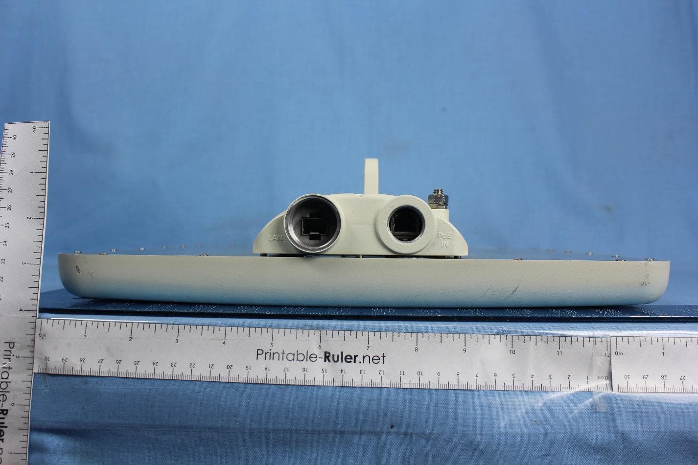
Radwin Ltd. FCC ID:Q3KAMWL1580 Date: September 2006 Page 1 of 8 EXTERNAL PHOTOGRAPHS This document contains 7 photographs Radwin Ltd. FCC ID:Q3KAMWL1580 Date: September 2006 Page 2 of 8 Photograph No.1 Winlink 1000-F58/HP (ODU) front view Radwin Ltd. FCC ID:Q3KAMWL1580 Date: September 2006 Page 3 of 8 Photograph No.2 Winlink 1000-F58/HP (ODU) rear side view Radwin Ltd. FCC ID:Q3KAMWL1580 Date: September 2006 Page 4 of 8 Photograph No.3 WL1000-AIND/F58 general view Radwin Ltd. FCC ID:Q3KAMWL1580 Date: September 2006 Page 5 of 8 Photograph No.4 WL1000-AIND/F58 bottom view Radwin Ltd. FCC ID:Q3KAMWL1580 Date: September 2006 Page 6 of 8 Photograph No.5 WL1000-AIND/F58 rear side view Radwin Ltd. FCC ID:Q3KAMWL1580 Date: September 2006 Page 7 of 8 Photograph No.6 WL1000-AIND/F58 left side view Radwin Ltd. FCC ID:Q3KAMWL1580 Date: September 2006 Page 8 of 8 Photograph No.7 WL1000-AIND/F58 right side view
ID Label/Location Info
FCC ID:Q3KAMWL1580 Date: September 2006 Page 1 of 4 Label with FCC ID:Q3KAMWL1580 for AIND models Label with FCC ID:Q3KAMWL1580 for ODU model FCC ID:Q3KAMWL1580 Date: September 2006 Page 2 of 4 An ODU terminal shall bear the label with FCC ID:Q3KAMWL1580 and RADWIN logo on a back panel as shown in the photo below: FCC ID:Q3KAMWL1580 FCC ID:Q3KAMWL1580 Date: September 2006 Page 3 of 4 The statement according to FCC part 15 section 15.19 is affixed to indoor unit, connected by wires to ODU and marketed together. Winlink1000 Radwin Ltd. FCC ID:Q3KAMWL1580 Date: September 2006 Page 4 of 4 An AIND radio terminal shall bear 1) the label with FCC ID:Q3KAMWL1580 and RADWIN logo on a rear panel 2) the statement according to FCC part 15 section 15.19 on the device bottom as shown in the photos below. Label with FCC ID:Q3KAMWL1580 location on the AIND rear panel Label with FCC part 15 statement will be placed on the AIND bottom Winlink1000 Radwin Ltd.
Internal Photos
Radwin Ltd. FCC ID:Q3KAMWL1580 Date: September 2006 Page 1 of 22 INTERNAL PHOTOGRAPHS This document contains 21 photographs Radwin Ltd. FCC ID:Q3KAMWL1580 Date: September 2006 Page 2 of 22 Photograph No.1 WL1000-AIND/F58 internal view Radwin Ltd. FCC ID:Q3KAMWL1580 Date: September 2006 Page 3 of 22 Photograph No.2 WL1000-AIND/F58 internal view with ODU raised Radwin Ltd. FCC ID:Q3KAMWL1580 Date: September 2006 Page 4 of 22 Photograph No.3 WL1000-AIND/F58 antenna cable from RF card Radwin Ltd. FCC ID:Q3KAMWL1580 Date: September 2006 Page 5 of 22 Photograph No.4 WL1000-AIND/F58 antenna inside connector view Radwin Ltd. FCC ID:Q3KAMWL1580 Date: September 2006 Page 6 of 22 Photograph No.5 WL1000-AIND/F58 main PCB top view Radwin Ltd. FCC ID:Q3KAMWL1580 Date: September 2006 Page 7 of 22 Photograph No.6 WL1000-AIND/F58 main PCB second side view Radwin Ltd. FCC ID:Q3KAMWL1580 Date: September 2006 Page 8 of 22 Photograph No.7 WL1000-AIND/F58 power supply PCB top view Radwin Ltd. FCC ID:Q3KAMWL1580 Date: September 2006 Page 9 of 22 Photograph No.8 WL1000-AIND/F58 power supply PCB second side view Radwin Ltd. FCC ID:Q3KAMWL1580 Date: September 2006 Page 10 of 22 Photograph No.9 Winlink 1000-F58/HP (ODU) internal view Radwin Ltd. FCC ID:Q3KAMWL1580 Date: September 2006 Page 11 of 22 Photograph No.10 Winlink 1000-F58/HP (ODU) internal view without cover Radwin Ltd. FCC ID:Q3KAMWL1580 Date: September 2006 Page 12 of 22 Photograph No.11 Winlink 1000-F58/HP (ODU) internal view, PCB removed from the case Radwin Ltd. FCC ID:Q3KAMWL1580 Date: September 2006 Page 13 of 22 Photograph No.12 Winlink 1000-F58/HP (ODU) main PCB front view Radwin Ltd. FCC ID:Q3KAMWL1580 Date: September 2006 Page 14 of 22 Photograph No.13 Winlink 1000-F58/HP (ODU) main PCB second side view Radwin Ltd. FCC ID:Q3KAMWL1580 Date: September 2006 Page 15 of 22 Photograph No.14 ODU main PCB with RF card Radwin Ltd. FCC ID:Q3KAMWL1580 Date: September 2006 Page 16 of 22 Photograph No.15 ODU main PCB with RF card removed Radwin Ltd. FCC ID:Q3KAMWL1580 Date: September 2006 Page 17 of 22 Photograph No.16 RF card front view Radwin Ltd. FCC ID:Q3KAMWL1580 Date: September 2006 Page 18 of 22 Photograph No.17 RF card with shield removed Radwin Ltd. FCC ID:Q3KAMWL1580 Date: September 2006 Page 19 of 22 Photograph No.18 RF card components underneath shield Radwin Ltd. FCC ID:Q3KAMWL1580 Date: September 2006 Page 20 of 22 Photograph No.19 RF card second side view Radwin Ltd. FCC ID:Q3KAMWL1580 Date: September 2006 Page 21 of 22 Photograph No.20 RF card with shield removed view Radwin Ltd. FCC ID:Q3KAMWL1580 Date: September 2006 Page 22 of 22 Photograph No.21 RF PCB second side view
Operational Description
WinLink™ 1000 Family High Capacity Carrier Class Radio Systems WinLinkô 1000 family of products is a carrier-class, high capacity and extremely competitive Point to Point broadband wireless transmission solution. It packs Legacy TDM and Ethernet services over 2.4GHz and 4.9-5.9GHz spectrum bands and is suitable for deployment in FCC and ETSI regulated countries. WinLinkô 1000 provides high capacity connectivity of up to 54 Mbps and allows for rapid deployment of E1/T1s and Ethernet links at a fraction of any alternatives' cost. WinLinkô 1000 efficiently addresses service providers and enterprises, requiring immediate deployment of affordable, carrier-class, long range and high capacity connectivity solutions. Available at multiple frequency bands and at various configurations, all WinLinkô 1000 products are highly robust, simple to install and extremely competitive. Highlights • High data rate, up to 54Mbps • Long Range, up to 80 Km • Integrated solution for nxE1s/T1s and Fast Ethernet • Carrier-Class in various spectrum bands: 5.725 ñ 5.850 GHz 5.470 ñ 5.725 GHz 5.250 ñ 5.350 GHz 4.940 ñ 4.990 GHz 2.400 ñ 2.4835 GHz • Compliant with FCC, IC and ETSI regulations • Complete SNMP based local and remote management, integrated with SNMPc and HPOV. Key Benefits • Short time to service • License exempt frequencies remove regulatory overhead and delays • Wireless connectivity instead of private line leasing from service providers, reducing costs • Compact integrated solution that is simple to install and operate Typical Applications Remote Sites Connectivity WinLinkô 1000 is offered to enterprises with multiple sites that require a cost effective and transparent connection of their LAN and PBXsystems across their various campuses. Broadband Access WinLink™ 1000 provides a broadband access solution, offering broadband Ethernet and Leased Line services to Small and Medium Enterprises (SMEs). Backhauling WinLink™ 1000 backhauls traffic from cellular base-stations, Hotspots (WiFi) or points of presence (POPs) of wireless ISPs to the backbone network. WinLink™ 1000 Family Product specifications Configuration Architecture Indoor Unit: IDU-E (Enterprise form-factor), IDU-C , AIND (Carrier form-factor) Outdoor Unit: ODU IDU to ODU Interface Outdoor CAT-5 cable; Maximum cable length: 100m Radio 2.400 ñ 2.4835 GHz 4.940 ñ 4.990 GHz Frequency Bands 5.250 ñ 5.350 GHz 5.470 ñ 5.725 GHz (includes DFS/TPC) 5.725 ñ 5.850 GHz Data Rate Configurable up to 54Mbps (bi-directional) Channel Bandwidth 20 MHz Duplex Technique TDD Modulation OFDM ñ BPSK/QPSK/16QAM/64QAM Transmit Power for 4.9GHz 16 dBm max limited @20MHz BW 15.5 dBm max limited @10MHz BW 15.6 dBm max limited for @5MHz BW Transmit Power for 5.4GHz 7.1 dBm max limited @20MHz BW with 22 dBi antenna 1.2 dBm max limited @20MHz BW with 28 dBi antenna Transmit Power for 5.8GHz/HP and AIND 29.7 dBm max @ 5MHz, 10MHz, 20MHz BW Page 2 of 4 Received Dynamic Range >60dB Error Correction FEC k=1/2, 2/3, 3/4 Encryption AES 128 LAN Interface Type 10/100BaseT Interface with Auto-negotiation (IEEE 802.3) Number of Ethernet Ports 1, 2 Framing/Coding IEEE 802.3/U Bridging Self-learning up to 2047 MAC addresses IEEE 802.1Q Traffic Handling MAC layer bridging, self-learning Data Latency 3msec typical Line Impedance 100Ω VLAN Support Transparent Connector RJ-45 E1/T1 Interface Framing Unframed (transparent) Number of E1/T1 Ports 1, 2, 4 Standard Compliance G.703, G.826 Timing Independent Tx and Rx timing Line Code E1: HDB3 @ 2.048 Mbps T1: B8ZS/AMI @ 1.544 Mbps Latency 8msec Impedance E1-120Ω, balanced T1-100Ω, balanced Connector RJ-45 Jitter & Wander According to G.823, G.824 Management Protocol SNMP based Network Management Supports SNMPc and HPOV Upgrade Capabilities Local and remote software upgrade Diagnostics Local and remote loopback testing Mechanics ODU Dimensions (includes 1ft flat integrated antenna) 30.5cm(H) x 30.5cm(W) x 5.8cm(D) Weight: 1.5kg/3.3lb ODU Dimensions (integrated antenna not included) 24.5cm(H) x 13.5cm(W) x 4.0cm(D) Weight: 1.0kg/2.2lb IDU-E Dimensions 16.5cm(H) x 23.6cm(W) x 4.5cm(D) Weight: 0.5kg/1.1lb IDU-C, and AIND Dimensions 43cm(H) x 29cm(W) x 4.5cm(D) Weight: 1.5kg/3.3lb Power and Mounting Power Feeding 110/220VAC, 50/60Hz, -48VDC Power Consumption ODU with IDU-E, 10W Max ODU with IDU-C, 14W Max AIND, 14W Max Mounting Pole and Wall Environmental Outdoor Unit Enclosure All weather cases ODU Operating Temperatures -35∞C - 60∞C / -31∞F - 140∞F IDU Operating Temperatures -5∞C - 45∞C / 23∞F - 113∞F AIND Operating Temperatures -35∞C - 60∞C / -31∞F - 140∞F Humidity Up to 90% non-condensing Page 3 of 4 Antennas 2.400-2.4835 4.940-4.990 5.250-5.350 5.470-5.725 5.725-5.850 GHz GHz GHz GHz GHz 1ft Integrated Antenna Gain 17dBi - 22dBi 22dBi 22dBi external Beam Width 20∞ 9∞ 9∞ 9∞ Polarization Linear N/A Linear Linear Linear 2ft External Antenna Gain 24dBi 27dBi 28dBi 28dBi 28dBi Beam Width 8∞ 4.5∞ 4.5∞ 4.5∞ 4.5∞ Polarization Linear Linear Linear Linear Linear * Higher gain antennas are available upon request Regulation 2.400-2.4835 4.940-4.990 5.250-5.350 5.470-5.725 5.725-5.850 GHz GHz GHz GHz GHz Radio FCC: 47CFR Part 15, Part 90 Part 15, Part 15, Subpart C Subpart E Subparts C&B IC RSS-210 RSS-210 RSS-210 ETSI EN 300 328 EN 300 216 EN 300 440 V1.2.1 V1.3.1 Dynamic Supported Supported Supported Supported Supported Frequency complies Selection and with Transmission EN 301 893 Power Control V1.2.2 (DFS/TPC) Safety TUV 60950, According to UL 60950 CAN-USA C22.2 No.60950 EMC FCC CFR Part15, Subpart B CAN-ETSI EN 301 489-1 Environmental ETSI IEC 60721-3-4 Class 4M5 IP67 Page 4 of 4
RF Exposure Info
Radwin Ltd. FCC ID:Q3KAMWL1580 Date: September 2006 RF_evaluation_17204.doc RF exposure evaluation according to §15.247(e)(i) and §1.1307 Limit for power density for general population/uncontrolled exposure is 1 mW/cm 2 (for 1500 –100,000 MHz frequency range). The power density P (mW/cm 2 ) = P T / 4π ππ π r 2 P T is the transmitted power, which is equal to the peak transmitter output power 29.7 dBm plus maximum antenna gain 32.5 dBi, the maximum equivalent isotropically radiated power EIRP is P T = 29.7 dBm +32.5 dBi = 62.2 dBm = 1659586 mW. The minimum safe distance “r”, where RF exposure does not exceed FCC permissible limit, is r = sqrt { P T / (Px4π)} = sqrt {1659586 / 12.56} = 364 cm. The warning has been inserted in User Manual.
Test Report
Hermon Laboratories Ltd. P.O.Box 23, Binyamina 30500, Israel Tel. +972 4628 8001 Fax. +972 4628 8277 E-mail: [email protected] Page 1 of 243 Report ID: RADRAD_FCC.17204_rev1.doc Date of Issue: 7/31/2006 Electrical TEST REPORT ACCORDING TO: FCC part 15 subpart C, §15.247 FOR: RadWin Ltd. High power broadband wireless transmission system Models: WinLink 1000-F58/HP, WL1000-AIND/F58/FCC/EXT/4T1 Airmux-200/AIND/F58/FCC/EXT/4T1 FibeAir-48-AIND-58-EX-AN-2FE-4T1 MRL-500- AIND/F58/FCC/EXT/4T1 This report is in conformity with ISO/ IEC 17025. The A2LA logo endorsement applies only to the test methods and the standards that are listed in the scope of Hermon Laboratories accreditation. The test results relate only to the items tested. This test report shall not be reproduced in any form except in full with the written approval of Hermon Laboratories Ltd. Report ID: RADRAD_FCC.17204_rev1.doc Date of Issue: 7/31/2006 Page 2 of 243 Table of contents 1 Applicant information..................................................................................................................................................... 3 2 Equipment under test attributes .................................................................................................................................... 3 3 Manufacturer information .............................................................................................................................................. 3 4 Test details.................................................................................................................................................................... 3 5 Tests summary.............................................................................................................................................................. 4 6 EUT description............................................................................................................................................................. 5 6.1 General information....................................................................................................................................................... 5 6.2 Ports and lines .............................................................................................................................................................. 5 6.3 Support and test equipment .......................................................................................................................................... 5 6.4 Operating frequencies ................................................................................................................................................... 5 6.5 Changes made in the EUT ............................................................................................................................................ 6 6.6 Test configuration.......................................................................................................................................................... 6 6.7 Transmitter characteristics ............................................................................................................................................ 7 7 Transmitter tests according to 47CFR part 15 subpart C requirements ........................................................................ 8 7.1 Minimum 6 dB bandwidth .............................................................................................................................................. 8 7.2 Peak output power ...................................................................................................................................................... 19 7.3 Spurious emissions at RF antenna connector ............................................................................................................. 30 7.4 Field strength of spurious emissions of the ODU with 32.5 dBi antenna ..................................................................... 53 7.5 Field strength of spurious emissions of the ODU with 22 dBi antenna ........................................................................ 86 7.6 Field strength of spurious emissions of the ODU with 28 dBi antenna ...................................................................... 113 7.7 Field strength of spurious emissions of the AIND with 28 dBi antenna ..................................................................... 144 7.8 Field strength of spurious emissions of the AIND with 32.5 dBi antenna .................................................................. 174 7.9 Peak spectral power density ..................................................................................................................................... 205 7.10 Conducted emissions ................................................................................................................................................ 225 8 APPENDIX A Test equipment and ancillaries used for tests..................................................................................... 231 9 APPENDIX B Measurement uncertainties.....................................…
Text truncated - open the document above for the full version.
Contact Information
Applicant
Shlomo Weiss(Standardization Officer)
Technical Contact
Test Firm
Hermon LaboratoriesGeorge Shleimovich
Technical Specifications
| # | Rule Parts | Frequency Range | Power Output |
|---|---|---|---|
| 1 | 15C | 5.74 GHz - 5.83 GHz | 927.00 mW |
Other Applications from Radwin Ltd.
Q3K-PTP5GAX
Feb 25, 20235 GHz High Performance PtP Outdoor Unit
Equipment Class
NII - Unlicensed National Information Infrastructure TX
Q3K-NEO5X
Apr 27, 2021Single Carrier 5.x GHz Base Station with Beamforming Antenna, Dual Carrier 5.x GHz Base Station with Beamforming Antenna
Equipment Class
NII - Unlicensed National Information Infrastructure TX
Q3K-5XSUALMOD
Apr 13, 20215 GHz SU/Alpha Board
Equipment Class
NII - Unlicensed National Information Infrastructure TX
Q3K-5XACMODMS
Sep 13, 20205 GHz MS RF Module
Equipment Class
NII - Unlicensed National Information Infrastructure TX
Q3K-TRBR600G
Aug 25, 2020Point to point/point to multipoint 57-71 GHz radio transceiver
Equipment Class
DXX - Part 15 Low Power Communication Device Transmitter