Q3KRW2025Outdoor radio unit operating in the 2.5-2.7 GHz (BRS) band
Radwin Ltd.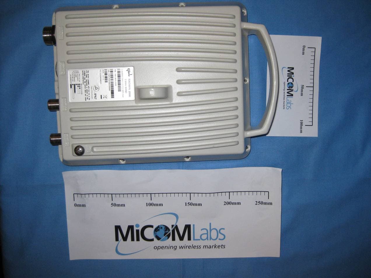
Click to zoom
Application Details
- Equipment Class
- TNB - Licensed Non-Broadcast Station Transmitter
- Date of Grant
- Mar 23, 2011
- Application Purpose
- Original Equipment
- Date of Application
- Mar 23, 2011
- Equipment Note
- Outdoor radio unit operating in the 2.5-2.7 GHz (BRS) band
- Frequency Range
- 2513.00000000 - 2679.00000000
- Company
- Radwin Ltd.
- Country
- Israel
Documents & Files
Document Text
Text extracted from the exhibit documents filed with the FCC. Open a document above to read the original.
Users Manual
RADWIN 2000 Broadband Wireless Transmission System USER MANUAL RELEASES 2.5.40 UM 2000-2540/02.11 RADWIN 2000 User ManualRelease 2.5.40i RADWIN 2000 User Manual Notice This manual contains information that is proprietary to RADWIN Ltd. (RADWIN hereafter). No part of this publication may be reproduced in any form whatsoever without prior written approval by RADWIN. Right, title and interest, all information, copyrights, patents, know-how, trade secrets and other intellectual property or other proprietary rights relating to this manual and to the RADWIN products and any software components contained therein are proprietary products of RADWIN protected under international copyright law and shall be and remain solely with RADWIN. The RADWIN name is a registered trademark of RADWIN Ltd. No right, license, or interest to such trademark is granted hereunder, and you agree that no such right, license, or interest shall be asserted by you with respect to such trademark. You shall not copy, reverse compile or reverse assemble all or any portion of the User Manual or any other RADWIN documentation or products. You are prohibited from, and shall not, directly or indirectly, develop, market, distribute, license, or sell any product that supports substantially similar functionality based or derived in any way from RADWIN products.Your undertaking in this paragraph shall survive the termination of this Agreement. This Agreement is effective upon your opening of a RADWIN product package and shall continue until terminated. RADWIN may terminate this Agreement upon the breach by you of any term thereof. Upon such termination by RADWIN, you agree to return to RADWIN any RADWIN products and documentation and all copies and portions thereof. For further information contact RADWIN at one of the addresses under Worldwide Contacts below or contact your local distributor. Disclaimer The parameters quoted in this document must be specifically confirmed in writing before they become applicable to any particular order or contract. RADWIN reserves the right to make alterations or amendments to the detail specification at its discretion. The publication of information in this document does not imply freedom from patent or other rights of RADWIN, or others. Trademarks WinLink 1000 and RADWIN 2000 are trademarks of RADWIN Ltd. Windows 2000, XP Pro, Vista, Windows 7 and Internet Explorer are trademarks of Microsoft Inc. Mozilla and Firefox are trademarks of the Mozilla Foundation. Other product names are trademarks of their respective manufacturers. RADWIN 2000 User ManualRelease 2.5.40ii RADWIN Worldwide Offices Corporate and EMEA Regional Headquarters Corporate and EMEA Headquarters 27 Habarzel Street Tel Aviv, 69710 Israel Tel: +972.3.766.2900 Fax: +972.3.766.2902 Email: [email protected] North America Regional Headquarters 900 Corporate Drive Mahwah, NJ, 07430 USA Tel: +1-877-RADWIN US (+1-877 723-9468) Tel: +1-201-252-4224 Fax: +1-201-621-8911 Email: [email protected] Customer Support - North America: Hours: 9 am - 6 pm EST (Mon - Fri) Email: [email protected] APAC Regional Headquarters 53A, Grange Road #15-02 Spring Grove ,249566 Singapore Tel: +65.6638.7864 Email: [email protected] RADWIN Regional Offices RADWIN Brazil Av. Chucri Zaidan, 920 – 9º São Paulo, 04583-904 Brazil Tel: +55.11.3048-4110 Email: [email protected] RADWIN Mexico Quinto #20 Col El Centinela Mexico, DF, O4450 Mexico Tel: +52 (55) 5689 8970 Email: [email protected] RADWIN Peru Av. Antares 213 Lima, 33 Peru Tel: +511.6285105 Fax: +511-990304095 Email: [email protected] RADWIN India E-13,B-1 Extn., Mohan Co-operative Industrial Estate New Delhi, 110 044 India Tel: +91-11-40539178 Email: [email protected] RADWIN Philippines 5 Bur Bank St. Laguna, Belair, Santa Rosa Laguna Philippines Tel: +63 928 7668230 Email: [email protected] RADWIN South Africa P.O. Box 3554, Rivonia Johannesburg ,2128 South Africa Tel: +27 (0)82 551 5600 Email: [email protected] RADWIN Italy and Spain Piazza Arenella 7/H Napoli ,80128 Italy Tel:+390815564116 Fax: +39335433620 Email: [email protected] RADWIN Central America Calle La Cañada # 108-E Jardines de la Hacienda Ciudad Merliot El Salvador Tel: +503 2278-5628 Email: [email protected] RADWIN South East Asia All Season Mansion 87/38 Wireless Road Lumpinee Bangkok ,10330 Thailand Tel: +66811707503 Email: [email protected] RADWIN 2000 User ManualRelease 2.5.40iii Regulatory Compliance General Note This system has achieved Type Approval in various countries around the world. This means that the system has been tested against various local technical regulations and found to comply. The frequency bands in which the system operates may be “unlicensed” and in these bands, the system can be used provided it does not cause interference. FCC - Compliance This equipment has been tested and found to comply with the limits for a Class B digital device, pursuant to Part 15 of the FCC Rules. These limits are designed to provide reasonable protection against harmful interference in a residential installation. This equipment generates, uses and can radiate radio frequency energy and, if not installed and used in accordance with the instructions, may cause harmful interference to radio communications. However, there is no guarantee that interference will not occur in a particular installation. If this equipment does cause harmful interference to radio or television reception, which can be determined by turning the equipment off and on, the user is encouraged to try to correct the interference by one or more of the following measures: • Reorient or relocate the receiving antenna. • Increase the separation between the equipment and receiver. • Connect the equipment into an outlet on a circuit different from that to which the receiver is connected. Consult the dealer or an experienced radio/TV technician for help. Changes or modifications to this equipment not expressly approved by the party responsible for compliance could void the…
Text truncated - open the document above for the full version.
Users Manual
Configuring the GSUChapter 11 RADWIN 2000 User ManualRelease 2.5.4011-8 Site Configuration: GPS Sync Unit This window is the main GSU configuration tool: Figure 11-8: Site Configuration: GPS Sync Unit 1. Setting the RFP for HSS The GSU is automatically configured as HSS Master (HSM). If the hub site consists only of WinLink 1000 units, then any suitable RFP may be chosen. If there are one or more RADWIN 2000 units, you must use RFP B or E. The permitted RFPs are also dependent on channel bandwidth and are color coded as fol- lows: Note The 1000 and 2000 labels refer to WinLink 1000 and RADWIN 2000 radios, respectively. The actual annotation seen may vary, but the intention should be clear. Note Ensure that no other collocated ODU is configured as HSM. You May use RFP/ Channel Bandwidth combinations with this color For these collocated radios WinLink 1000 only RADWIN 2000 only WinLink 1000 and RADWIN 2000 together None - unavailable Configuring the GSUChapter 11 RADWIN 2000 User ManualRelease 2.5.4011-9 There is a further restriction: If there are two distributed sites transmitting to each other, they must both use the same RFP. This requirement, together with use of shifted transmis- sion phase (item 3 below), ensures that communicating distributed sites to not interfere with each other by transmitting simultaneously. Two GSU managed sites transmitting with shifted transmission phase and using the same RFP, transmit one half a RFD apart (see Figure 11-3 above). 2. Setting the Tx Transmission Ratio Since the GSU is always HSM, it must be able to cater for hub site RADWIN 2000 C based links. (See the RADWIN 2000 User Manual, Chapter 5). If you use asymmetric allocation, shifted transmission phase becomes unavailable and you cannot “cascade” links as described in step 1. 3. Choosing the Transmission Phase Chose the Transmission Phase in accordance with considerations in step 1 above. If you choose Shifted Phase then the Asymmetric Ratio selector is disabled. Site Configuration: Management Figure 11-9: Site Configuration: Management Here you set the GSU IP address, subnet mask and gateway. You also set trap addresses here. It is identical to the corresponding panel for WinLink 1000. Configuring the GSUChapter 11 RADWIN 2000 User ManualRelease 2.5.4011-10 Site Configuration: Inventory Figure 11-10: Site Configuration: Inventory Site Configuration: Security You can only change the SNMP Community stings: Figure 11-11: Site Configuration: Security Site Configuration: Date and Time ODU Recent events, alarms and traps are time-stamped from the time method chosen here (NTP, managing computer, ODU default). Configuring the GSUChapter 11 RADWIN 2000 User ManualRelease 2.5.4011-11 Figure 11-12: Setting the date and time for trap reporting Site Configuration: Operations The only available action here is Restore System Defaults: Figure 11-13: Site Configuration: Operations GSU PreferencesChapter 11 RADWIN 2000 User ManualRelease 2.5.4011-12 GSU Preferences The Preferences window adds a new tab for the GSU: Figure 11-14: Site Configuration: Operations You may chose the units for latitude/longitude coordinates. GSU Monitoring and Diagnostics The monitoring and diagnostic reports are similar to those of WinLink 1000. GSU Telnet Support To configure the GSU with Telnet, start a Telnet session, using telnet <GSU_ipaddr>. For example, if you run Telnet as follows, telnet 192.168.222.20 you will be asked for a user name and password. You must log on with administrator privilege under user name, admin and password netman. The available commands are the same as for WinLink 1000 with the addition of four addi- tional display commands and three additional set commands. The additional display commands are display rfp display ratio display tx_phase display gpsinfo The last one display gpsinfo, is the most interesting: [email protected]> display gpsinfo Current GPS time 102941.000 Software Update for GSUsChapter 11 RADWIN 2000 User ManualRelease 2.5.4011-13 Current GPS latitude 51.500000 Current GPS N\S Indicator N Current GPS longitude 0.000000 Current GPS E\W Indicator E Current GPS number of satellites 09 Current GPS altitude 84.0 Command "display gpsinfo" finished OK. The three additional set commands are set rfp <index> (2-6) set ratio <ratio> set tx_phase <mode:1=normal,2=shifted> Software Update for GSUs All GSUs in a distributed site can be updated simultaneously. Use an IP list as described in Chapter 15. RADWIN 2000 Broadband Wireless Transmission System USER MANUAL RELEASE 2.5.40 Part 3: Advanced Installation UM 2000-2540/02.11 RADWIN 2000 User ManualRelease 2.5.4012-1 Chapter 12 Monitored Hot Standby Installation Procedure What is a RADWIN Monitored Hot Standby The RADWIN Monitored Hot Standby (MHS a.k.a 1+1) is a duplicated link set up as a primary link and a secondary link in hot standby mode as shown in Figure 12-1 below. Figure 12-1: RADWIN Monitored Hot Standby What RADWIN MHS providesChapter 12 RADWIN 2000 User ManualRelease 2.5.4012-2 RADWIN MHS provides redundancy and backup to TDM services. It is designed to provide high reliability high-capacity Point-to-Point links. The RADWIN MHS is - • Designed to provide redundancy and high reliability for carrier class operators • Optimized for high capacity links operating in license-free bands • A comprehensive solution providing protection against both equipment failure and loss of air interface, by simple connectivity between a primary link and a secondary link The main service redundancy features of the RADWIN MHS are – • TDM service cut-over from the primary to the secondary link is completely automatic • TDM service cut-over time no more than 50 ms • Automatic restore to primary link as soon as it becomes available • Support for up to sixteen TDM channels for RADWIN 2000 and four TDM channels for WinLink 1000. MHS is supported between - • two WinLink 1000 links • two RADWIN 2000 links • a WinLink 1000 link and a RADWIN 2000 link. What RADWIN MHS …
Text truncated - open the document above for the full version.
Cover Letter(s)
Letter of Authorization Company: Radwin Ltd. Address: 27 Habarzel Street, Tel Aviv, Israel, 69710 Product Name: Outdoor radio unit operating in the 2.5-2.7 GHz (BRS) band Model Number: RADWIN 2000 2.5GHz BAND We authorize MiCOM Labs, 440 Boulder Court, Suite 200, Pleasanton, CA 94566, USA, to act on our behalf on all matters concerning the above named equipment. This shall include the following: - Testing - Approval applications and procedures - Payment of approval fees We declare that MiCOM Labs, 440 Boulder Court, Suite 200, Pleasanton, CA 94566, USA, is allowed to forward all information related to the approval project to the applied notified body and to the notification entities and to discuss any issues concerning the approval application. Any and all acts carried out by MiCOM Labs on our behalf shall have the same effect as acts of our own. Name: Itai Rubinstein Date: February 15, 2011 Title: Engineering Department Manager Signature of applicant
Cover Letter(s)
2/21/2011 Federal Communications Commission Equipment Authorization Branch 7435 Oakland Mills Road Columbia, MD 21046 Request for Confidentiality Company name: Radwin Ltd. FCC ID: Q3KRW2025 FCC Part 27 Certification Gentlemen, In accordance with 0.459 of CFR 47, Radwin Ltd. hereby requests confidentiality of the following documents for the subject application: • Antenna Details • Block Diagrams • Schematics • Bill of Material • Internal Photographs These documents contain detailed system and equipment description and related information about the product which Radwin Ltd. considers to be proprietary, confidential and a custom design and otherwise would not release to the general public. Since the design is a basis from which future technological products will evolve, Radwin Ltd. considers that this information would be of benefit to its competitors and that the disclosure of the information in these documents would give competitors an unfair advantage in the market. Sincerely, Itai Rubinstein Engineering Dept. Manager 27 Habarzel Street Tel Aviv 69710 Israel
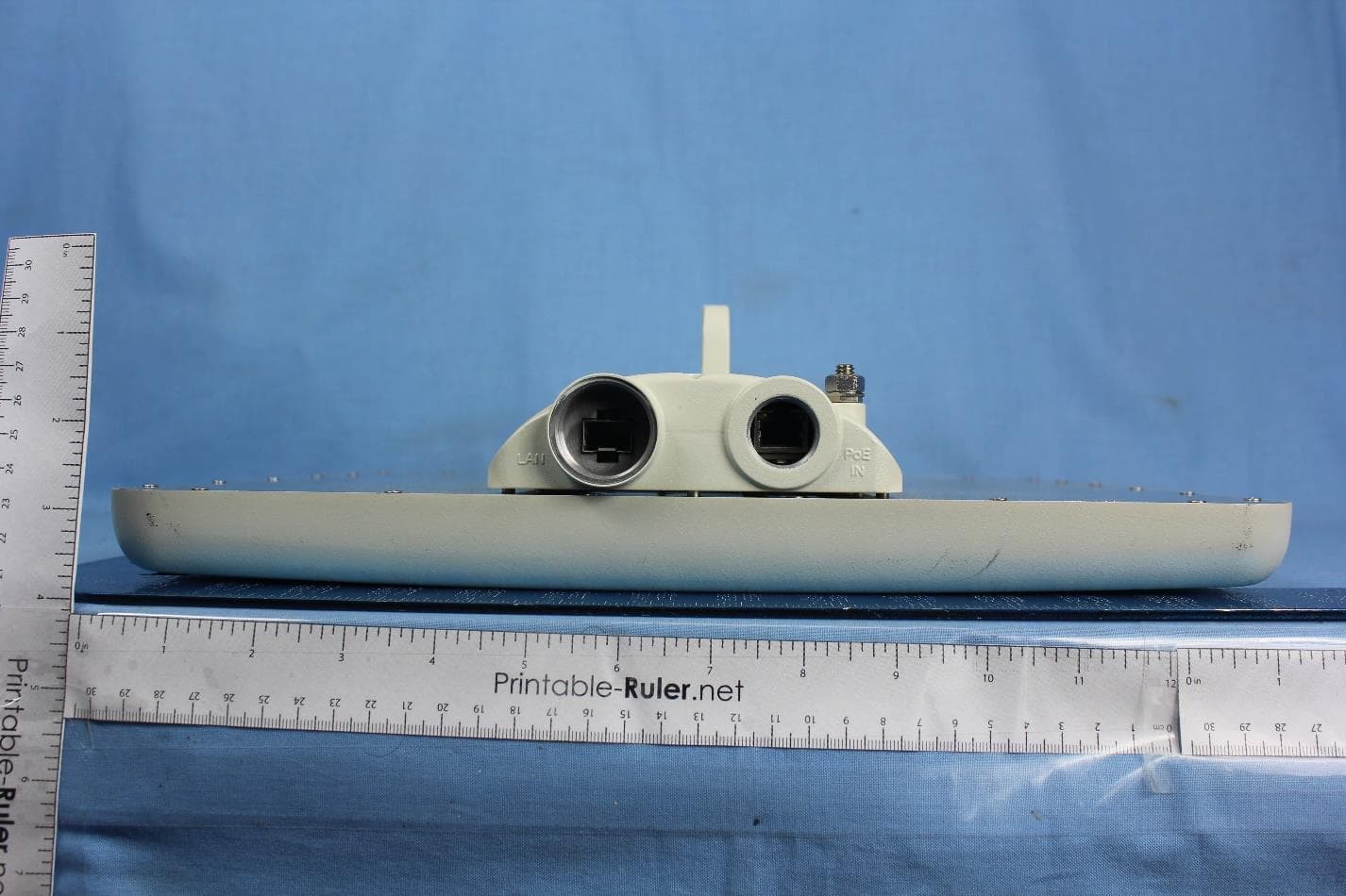
External Photos
the wireless lab 21 February 2011 Radwin Ltd. RADWIN 2000 2.5GHz BAND External Photographs Top View MiCOM Labs, 440 Boulder Court, Suite 200, Pleasanton, CA 94566 Tel: +1 (925) 462-0304, Fax: +1 (925) 462-0306, Web: www.micomlabs.com the wireless lab Side View Page 2 of 2
ID Label/Location Info
the wireless lab 3 March 2011 Radwin Ltd. RADWIN 2000 2.5GHz BAND Label Location MiCOM Labs, 440 Boulder Court, Suite 200, Pleasanton, CA 94566 Tel: +1 (925) 462-0304, Fax: +1 (925) 462-0306, Web: www.micomlabs.com
Test Report
Test of RADWIN 2000 2.5 GHz BAND To: FCC 47 CFR Part 2 7, Subpart M Test Report Serial No.: RDWN04-U1 Rev A TEST REPORT From This test report may be reproduced in full only. The document may only be updated by MiCOM Labs personnel. Any changes will be noted in the Document History section of the report. MiCOM Labs is an ISO 17025 Accredited Testing Laboratory TESTING CERTIFICATE #2381.01 Test of: Radwin 2000 2.5 GHz BAND To: FCC 47 CFR Part 27 Subpart M Test Report Serial No.: RDWN04-U1 Rev A This report supersedes: None Applicant: Radwin Ltd 27 Habarzel Street Tel Aviv 69710 Israel Product Function: Dual Antenna Port 2.5 GHz BAND PtP Wireless Communication Copy No: pdf Issue Date: 28th February 2011 This Test Report is Issued Under the Authority of; MiCOM Labs, Inc. 440 Boulder Court, Suite 200 Pleasanton, CA 94566 USA Phone: +1 (925) 462-0304 Fax: +1 (925) 462-0306 www.micomlabs.com Title: RADWIN 2000 2.5 GHz BAND To: FCC 47 CFR Part 27 Subpart M Serial #: RDWN04-U1 Rev A Issue Date: 28th February 2011 Page: Page 3 of 107 This test report may be reproduced in full only. The document may only be updated by MiCOM Labs personnel. Any changes will be noted in the Document History section of the report. MiCOM Labs, 440 Boulder Court, Suite 200, Pleasanton, CA 94566 USA, Phone: 925.462.0304, Fax: 925.462.0306, www.micomlabs.com TABLE OF CONTENTS 1 ACCREDITATION, LISTINGS & RECOGNITION ..................................................... 5 1.1 TESTING ACCREDITATION .................................................................................... 5 1.2 RECOGNITION ......................................................................................................... 6 1.3 PRODUCT CERTIFICATION .................................................................................... 7 2 DOCUMENT HISTORY ............................................................................................... 8 3 TEST RESULT CERTIFICATE ................................................................................... 9 4 REFERENCES AND MEASUREMENT UNCERTAINTY ........................................ 10 4.1 Normative References ............................................................................................. 10 4.2 Test and Uncertainty Procedures ............................................................................ 10 5 TEST SUMMARY ...................................................................................................... 11 6 PRODUCT DETAILS AND TEST CONFIGURATIONS .......................................... 12 6.1 Test Program Scope ................................................................................................ 12 6.2 EUT Details.............................................................................................................. 14 6.3 External A.C. / D.C. Power Adaptor......................................................................... 15 6.4 Types of Modulation Supported ............................................................................... 15 6.5 Antenna Details ....................................................................................................... 15 6.6 Cabling and I/O Ports .............................................................................................. 15 6.7 EUT Configurations ................................................................................................. 16 6.8 Equipment Details.................................................................................................... 16 6.9 Test Configurations.................................................................................................. 17 6.10 Equipment Modifications.......................................................................................... 17 6.11 Deviations from the Test Standard .......................................................................... 17 7 TEST RESULTS ........................................................................................................ 18 7.1 26 dB and 99 % Occupied Bandwidth ..................................................................... 18 7.1.1 Measurement results for 5.5 MHz ............................................................19 7.1.2 Measurement results for 6.0 MHz ............................................................22 7.1.3 Measurement results for 10.0 MHz ..........................................................25 7.1.4 Measurement results for 20.0 MHz ..........................................................29 7.2 RF Output Power, Emission Mask, EIRP at the Antenna Terminals ....................... 33 7.2.1 Measurement results for 5.5 MHz ............................................................36 7.2.2 Measurement results for 6.0 MHz ............................................................39 7.2.3 Measurement results for 10.0 MHz ..........................................................42 7.2.4 Measurement results for 20.0 MHz ..........................................................46 7.2.5 Output Power V’s Antenna Gain (EIRP)...................................................50 7.3 Power Spectral Density ........................................................................................... 51 7.3.1 Measurement results for 5.5 MHz ............................................................54 7.3.2 Measurement results for 6.0 MHz ............................................................57 7.3.3 Measurement results for 10.0 MHz ..........................................................60 7.3.4 Measurement results for 20.0 MHz ..........................................................64 7.4 Frequency Stability .................................................................................................. 68 7.4.1 Measurement results for Extremes of Temperature.................................69 7.4.2 Measurement results for Ambient Temperature V’s Voltage Variation ....70 Title: RADWIN 2000 2.5 GHz BAND To: …
Text truncated - open the document above for the full version.
Test Setup Photos
the wireless lab 21 February 2011 Radwin Ltd. RADWIN 2000 2.5GHz BAND Test Setup Photographs Conducted RF Emissions - EUT MiCOM Labs, 440 Boulder Court, Suite 200, Pleasanton, CA 94566 Tel: +1 (925) 462-0304, Fax: +1 (925) 462-0306, Web: www.micomlabs.com the wireless lab Conducted RF Emissions - Test Equipment Page 2 of 4 the wireless lab Transmitter Radiated Spurious Emission above 1 GHz Page 3 of 4 the wireless lab AC Mains Conducted Emissions Page 4 of 4
Contact Information
Applicant
Shlomo Weiss(Standardization Officer)
Technical Contact
Test Firm
Micom LabsGordon Hurst
Technical Specifications
| # | Rule Parts | Frequency Range | Power Output | Emission | Tolerance |
|---|---|---|---|---|---|
| 3 | 27 | 2.51 GHz - 2.68 GHz | 275.00 mW | 20M0W7W | 1.7 ppm |
Other Applications from Radwin Ltd.
Q3K-PTP5GAX
Feb 25, 20235 GHz High Performance PtP Outdoor Unit
Equipment Class
NII - Unlicensed National Information Infrastructure TX
Q3K-NEO5X
Apr 27, 2021Single Carrier 5.x GHz Base Station with Beamforming Antenna, Dual Carrier 5.x GHz Base Station with Beamforming Antenna
Equipment Class
NII - Unlicensed National Information Infrastructure TX
Q3K-5XSUALMOD
Apr 13, 20215 GHz SU/Alpha Board
Equipment Class
NII - Unlicensed National Information Infrastructure TX
Q3K-5XACMODMS
Sep 13, 20205 GHz MS RF Module
Equipment Class
NII - Unlicensed National Information Infrastructure TX
Q3K-TRBR600G
Aug 25, 2020Point to point/point to multipoint 57-71 GHz radio transceiver
Equipment Class
DXX - Part 15 Low Power Communication Device Transmitter