Q3KRW2030Outdoor radio unit operating in 3.65 GHz band
Radwin Ltd.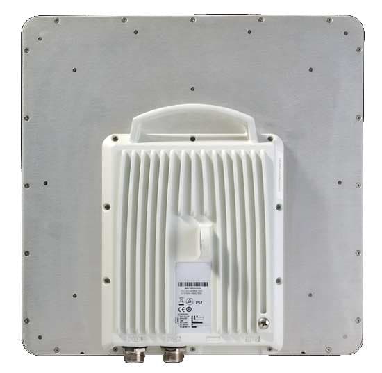
Click to zoom
Application Details
- Equipment Class
- TNB - Licensed Non-Broadcast Station Transmitter
- Date of Grant
- Dec 16, 2010
- Application Purpose
- Original Equipment
- Date of Application
- Nov 17, 2010
- Equipment Note
- Outdoor radio unit operating in 3.65 GHz band
- Frequency Range
- 3661.00000000 - 3664.00000000
- Company
- Radwin Ltd.
- Country
- Israel
Documents & Files
Document Text
Text extracted from the exhibit documents filed with the FCC. Open a document above to read the original.
Users Manual
UM 3000-2530/11.10 RADWIN 1000/2000/3000 Broadband Wireless Transmission System User Manual Version 2.5.30p1 RADWIN 1000/2000/3000 User ManualVersion 2.5.30p1i RADWIN 1000/2000/3000 User Manual Notice This manual contains information that is proprietary to RADWIN Ltd. (RADWIN hereafter). No part of this publication may be reproduced in any form whatsoever without prior written approval by RADWIN. Right, title and interest, all information, copyrights, patents, know-how, trade secrets and other intellectual property or other proprietary rights relating to this manual and to the RADWIN products and any software components contained therein are proprietary products of RADWIN protected under international copyright law and shall be and remain solely with RADWIN. The RADWIN name is a registered trademark of RADWIN Ltd. No right, license, or interest to such trademark is granted hereunder, and you agree that no such right, license, or interest shall be asserted by you with respect to such trademark. You shall not copy, reverse compile or reverse assemble all or any portion of the User Manual or any other RADWIN documentation or products. You are prohibited from, and shall not, directly or indirectly, develop, market, distribute, license, or sell any product that supports substantially similar functionality based or derived in any way from RADWIN products.Your undertaking in this paragraph shall survive the termination of this Agreement. This Agreement is effective upon your opening of a RADWIN product package and shall continue until terminated. RADWIN may terminate this Agreement upon the breach by you of any term thereof. Upon such termination by RADWIN, you agree to return to RADWIN any RADWIN products and documentation and all copies and portions thereof. For further information contact RADWIN at the address below or contact your local distributor. Disclaimer The parameters quoted in this document must be specifically confirmed in writing before they become applicable to any particular order or contract. RADWIN reserves the right to make alterations or amendments to the detail specification at its discretion. The publication of information in this document does not imply freedom from patent or other rights of RADWIN, or others. RADWIN 1000/2000/3000 User ManualVersion 2.5.30p1ii RADWIN Worldwide Offices For technical support contact: [email protected] For technical support in India only, contact: [email protected] For sales support contact: [email protected] Website: www.radwin.com Corporate Headquarters 27 Habarzel Street Tel Aviv, 69710 Israel Tel: +972 3 766 2917 Support Headquarter 27 Habarzel Street Tel Aviv, 69710 Israel Tel: +972 3 766 2900 Mobile: +972 54 766 0044 RADWIN North America 900 Corporate Drive Mahwah, NJ 07430 USA Tel (1): 1 800 444 7234 / 341 Tel (2): +1 201 529 1100 / 341 Latin America Headquarters Rua Grao Mogol 828 Belo Horizonte, MG 30310-010 Brazil Tel (1): +55 31 919 76 402 Tel (2): +972 54 758 6808 India Headquarters Mohan Co-operative Industrial Estate E-13, B-1 Extn New Delhi, 110044 India Tel: +91 11 4053 9180 APAC Headquarters 1 Jalan Kuala #13-01 The Morningside, 239639 Singapore Tel: +65 9878 3004 Indonesia Sales Office Jl. Jenderal Sudirman Kav. 86 Jakarta, 10220 Indonesia Tel: +62 8138 570 0657 Philippines Sales Office 37A. A luna St. West Rembo Makati City, 1200 Philippines Tel: +63 2882 6886 Mobile: +63 91 789 23427 China Sales Office Asian Games Village Huiyuan Gongyu J1312 Beijing 100101 China Tel: +86 010 8498 0629 RADWIN 1000/2000/3000 User ManualVersion 2.5.30p1iii Regulatory Compliance General Note This system has achieved Type Approval in various countries around the world. This means that the system has been tested against various local technical regulations and found to comply. The frequency bands in which the system operates may be “unlicensed” and in these bands, the system can be used provided it does not cause interference. FCC/IC - Compliance This equipment has been tested and found to comply with the limits for a Class B digital device, pursuant to Part 15 of the FCC Rules and ICES-003 of IC. These limits are designed to provide reasonable protection against harmful interference in a residential installation. This equipment generates, uses and can radiate radio frequency energy and, if not installed and used in accordance with the instructions, may cause harmful interference to radio communications. However, there is no guarantee that interference will not occur in a particular installation. If this equipment does cause harmful interference to radio or television reception, which can be determined by turning the equipment off and on, the user is encouraged to try to correct the interference by one or more of the following measures: • Reorient or relocate the receiving antenna. • Increase the separation between the equipment and receiver. • Connect the equipment into an outlet on a circuit different from that to which the receiver is connected. Consult the dealer or an experienced radio/TV technician for help. Changes or modifications to this equipment not expressly approved by the party responsible for compliance (RADWIN Ltd.) could void the user's authority to operate the equipment. Warning It is the responsibility of the installer to ensure that when using the outdoor antenna kits in the United States (or where FCC rules apply), only those antennas certified with the product are used. The use of any antenna other than those certified with the product is expressly forbidden in accordance to FCC rules CFR47 part 15.204. Caution In accordance to IC standard RSS-Gen - To reduce potential radio interference to other users, the antenna type and its gain should be so chosen that the equivalent isotropically radiated power (e.i.r.p) is not more than that permitted for successful communication Caution Outdoor units and antennas should be installed ONLY by experienced installation professionals who are familiar with local building and saf…
Text truncated - open the document above for the full version.
Users Manual
RADWIN 1000/2000/3000 User ManualVersion 2.5.30p16-1 Chapter 6 Site Configuration The Site Configuration dialog panels are used to configure parameters, which may differ between both sides of the link. The parameters configured using the Site Configuration dialog panels include (among others): • System settings • Air interface - Transmit (Tx) power and antenna • Network management including VLAN • Security settings • Date and time • Hub or Bridge mode In addition, the Link Site Configuration panels include several information windows: • Inventory - link hardware and software model details • External alarms indicators The Operations dialog offers a “doorway” to jump into installation mode reverting to factory settings. The Site Configuration dialog has its own main menu with the following extra functionality: • Backup configuration parameters to a text file • Restore configuration from a previously backed up configuration file • Enable/disable the site ODU buzzer • Jump back into installation mode keeping current configuration set- tings Configuring the Site Editing the Configuration Parameters by Site You can edit the configuration parameters for each site individually. The fol- lowing functions are available from the left side of the dialog box. Editing the Configuration Parameters by Site Chapter 6 RADWIN 1000/2000/3000 User ManualVersion 2.5.30p16-2 Figure 6-1: Configuration Dialog Box Functions on the left of the dialog box: Functions at the top of the dialog box: System Edit the contact person and location details. View the system details Air InterfaceChange the transmit power, cable loss, antenna type and settings InventoryView the hardware and software inventory (release numbers, model identification, MAC address) ManagementConfigure the IP address, Subnet Mask, Default Gateway, the Trap Destination and VLAN SecurityChange the Community Values and the Link Password Date and TimeSet the date and time of the link from an NTP servers otherwise AdvancedChoose Hub or Bridge ODU mode, set the Ethernet ports configuration, set the external alarm inputs, restore factory settings BackupSave the current configuration to an .ini file RestoreRestore the link configuration from the .ini file created by the backup Viewing Air Interface Details Chapter 6 RADWIN 1000/2000/3000 User ManualVersion 2.5.30p16-3 ¾To edit the Configuration Parameters: 1. Click the required site button on the main tool bar of the RADWIN Man- ager OR Click Configuration from the main menu and choose a site to config- ure. The Configuration dialog box opens (see figure 6-1 above). 2. Choose the appropriate item in the left hand list to open a dialog box. 3. Click Apply to save changes. In subsequent instructions, we will simply say “Choose a site to configure” on the understanding that the foregoing procedure is implied. Viewing Air Interface Details Click the Air Interface item in the left hand list. A window similar to the fol- lowing appears: Figure 6-2: Air interface details Installation Mode Return to Installation Mode for the entire link. Selecting the Mute check box before clicking the Install Mode button mutes the Beeper. MuteMutes the alignment tone in installation mode. Reactivate the beeper during alignment. Changing the Transmit Power Chapter 6 RADWIN 1000/2000/3000 User ManualVersion 2.5.30p16-4 Changing the Transmit Power Each site can have a different transmit power level. ¾To change the Transmit Power: 1. Choose a site to configure. The Configuration dialog box opens. 2. Choose Air Interface (see figure 6-3). 3. Choose the required Transmit (Tx) Power Level. 4. Click Apply to save the changes. Figure 6-3: Changing the Transmit Power Site Management: IP Address and VLAN Configuring the ODU Address Each site must be configured separately, first site A then site B. ¾To define the Management Addresses: 1. Choose a site to configure. Note The same considerations apply here as were noted in the Installation procedure on page 4-23. Configuring VLAN Settings Chapter 6 RADWIN 1000/2000/3000 User ManualVersion 2.5.30p16-5 The Configuration dialog box opens: Figure 6-4: Management Addresses - Site Configuration dialog box 5. Choose Management. 6. Enter the IP address of the ODU in the IP Address field. 7. Enter the Subnet Mask. 8. Enter the Default Gateway. 9. Enter the Trap Destination. This could be the IP address of the managing computer. The events log will be stored at this address. 10.Click Apply to save the changes. Configuring VLAN Settings VLAN Management enables separation of user traffic from management traffic whenever such separation is required. It is recommended that both sides of the link be configured with different VLAN IDs for management traf- fic. ¾To enable VLAN management: 1. Click Configuration from the main menu. Note If performing configuration from the RADWIN Manager, the IP address is that entered from the login screen. Configuring VLAN Settings Chapter 6 RADWIN 1000/2000/3000 User ManualVersion 2.5.30p16-6 2. Choose a site to configure. If you are configuring both sites, choose site B first. 3. Choose Management. 4. Open the VLAN tab. 5. Check the Enabled box. 6. Enter a VLAN ID. Its value should be between 1 and 4094. After entering the VLAN ID, only packets with the specified VLAN ID are processed for management purposes by the ODU. This includes all the protocols supported by the ODU (ICMP, SNMP, TELNET and NTP). The VLAN priority is used for the traffic sent from the ODU to the managing computer. Using VLAN for management traffic affects all types of man- agement connections (local, network and over the air). 7. Enter a Priority number between 0 and 7. 8. Change the VLAN ID and Priority of the managing computer NIC to be the same as those of steps 6 and 7 respectively. 9. Click Apply or OK. Figure 6-5: Configuring management traffic VLAN Settings Caution Changing this parameter causes the RADWIN Manager to immediately disconnect.To avoid inconvenience, you should verify the change by s…
Text truncated - open the document above for the full version.
Block Diagram
Radwin Ltd. IC:5100A-RW2030 Page 1 of 2 BLOCK DIAGRAM Radwin Ltd. IC:5100A-RW2030 Page 2 of 2 RADWIN 1000 3GHz BAND, RADWIN 2000 3GHz BAND, RADWIN 3000 3GHz BAND BLOCK DIAGRAM Operating frequency ranges: 3477.5 – 3647.5 MHz 3652.5 – 3672.5 MHz
Cover Letter(s)
RF_160, Issue 02 Declaration of Authorization We Name: Radwin Ltd. Address: 27 Habarzel street ................................................ . City: Tel Aviv 69710 ............................................................ . Country: Israel ........................................................................ . Declare that: Name Representative of agent: ............. (1) Agent Company name: Hermon Laboratories Ltd. Address: Harakevet Industrial Zone City: Binyamina 30500 Country Israel is authorized to apply for Certification of the following product(s): Product description: ... Outdoor radio unit operating in the 3.5/3.65 GHz band ............ . Type designation: ... RADWIN 1000 3GHz BAND / RADWIN 2000 3GHz BAND/ RADWIN 3000 3GHz BAND .................................... . Trademark: ................................................... . on our behalf. Date: 10/21/2010 ... .. City: Tel Aviv ...... .. Name: Itai Rubinstein ......... .. (2) Function: Engineering Department Manager .... Signature: .............................. . Notes: (1): Required for FCC application (2): For FCC it must be the Grantee Code “owner” or the authorized agent.
Cover Letter(s)
FCC, Request for non-disclosure Date: 16-Jul-10 RF_501, Issue 6 Page 1 of 1 Company Name: Radwin Ltd. Address : 27 Habarzel street City: Tel Aviv 69710 Country: Israel To: Telefication B.V., Dept. FCC TCB Edisonstraat 12A 6902 PK ZEVENAAR The Netherlands Subject: Request for confidentiality FCC ID: Q3KRW2030 Reference number: ###### Dear FCC TCB, 1. Long-Term Confidentiality Pursuant to 47 CFR Section 0.459(a) & (b), we hereby requests non-disclosure and confidential treatment of the following materials submitted in support of FCC certification application: Bill(s) of Material Block Diagrams Operational Description Schematic Diagrams Tune-up Procedure Above materials contain secrets, proprietary and technical information, which would customarily be guarded from competitors under 47 CFR, section 0.457(d)(2). Disclosure or publication or any portion of this company confidential material to other parties could cause substantial competitive harm and provide unjustified benefits for competitors. 2. Short-Term Confidentiality (STC) Pursuant to Public Notice DA 04-1705 of the Commission’s policy, in order to comply with the marketing regulations in 47 CFR §2.803 and the importation rules in 47 CFR §2.1204, a pplicant hereby requests Short-Term Confidential treatment of the following materials (note 1): Internal Photos User’s Manual Test Set-up Photos External Photos Justification: Request for Long Term Confidentiality for Internal photos attached. Planned Release Date STC: (notes 2, 3, 4, 5) Date: October 20,2010 Name and signature of applicant: Itai Rubinstein Notes: 1) A document or type of document can only have ONE type of confidentiality! 2) Short-Term confidentiality is in principle for 45 days from date of grant; it can be extended max 3 times (total time 180 days max.)! 3) FCC must be informed when marketing begins earlier. 4) Release takes place automatically thus extension must be requested in time. Telefication does not remind you of this! 5) Request for extension or for release must be received by Telefication at least 7 days before date of actual marketing or before expiration of the STC period
Cover Letter(s)
FCC Confidentiality Form October 20, 2010 Federal Communications Commission 7435 Oakland Mills Road Columbia, MD 21046 Gentlemen: This letter is to comply with Section 0.457(d)(2)(i) pertaining to confidential material. Radwin Ltd. would like the following documents regarding this submission for FCC ID: Q3KRW2030 to be kept confidential. 1) Internal_photos_20845. The product is a non-consumer device and is inaccessible to the general public. The product is mounted on top of large towers and mounting poles and serviceable only by the licensee or his designated technicians. The above material contains trade secrets or technical data, which would customarily be guarded from competitors. We do not want these documents to be accessible to the general public. Sincerely, Itai Rubinstein Engineering Department Manager Radwin Ltd Radwin Ltd. 27 Habarzel St Tel-Aviv, 69710, Israel, Tel- 972-3-766-2900, Fax-972-3-766-2902
External Photos
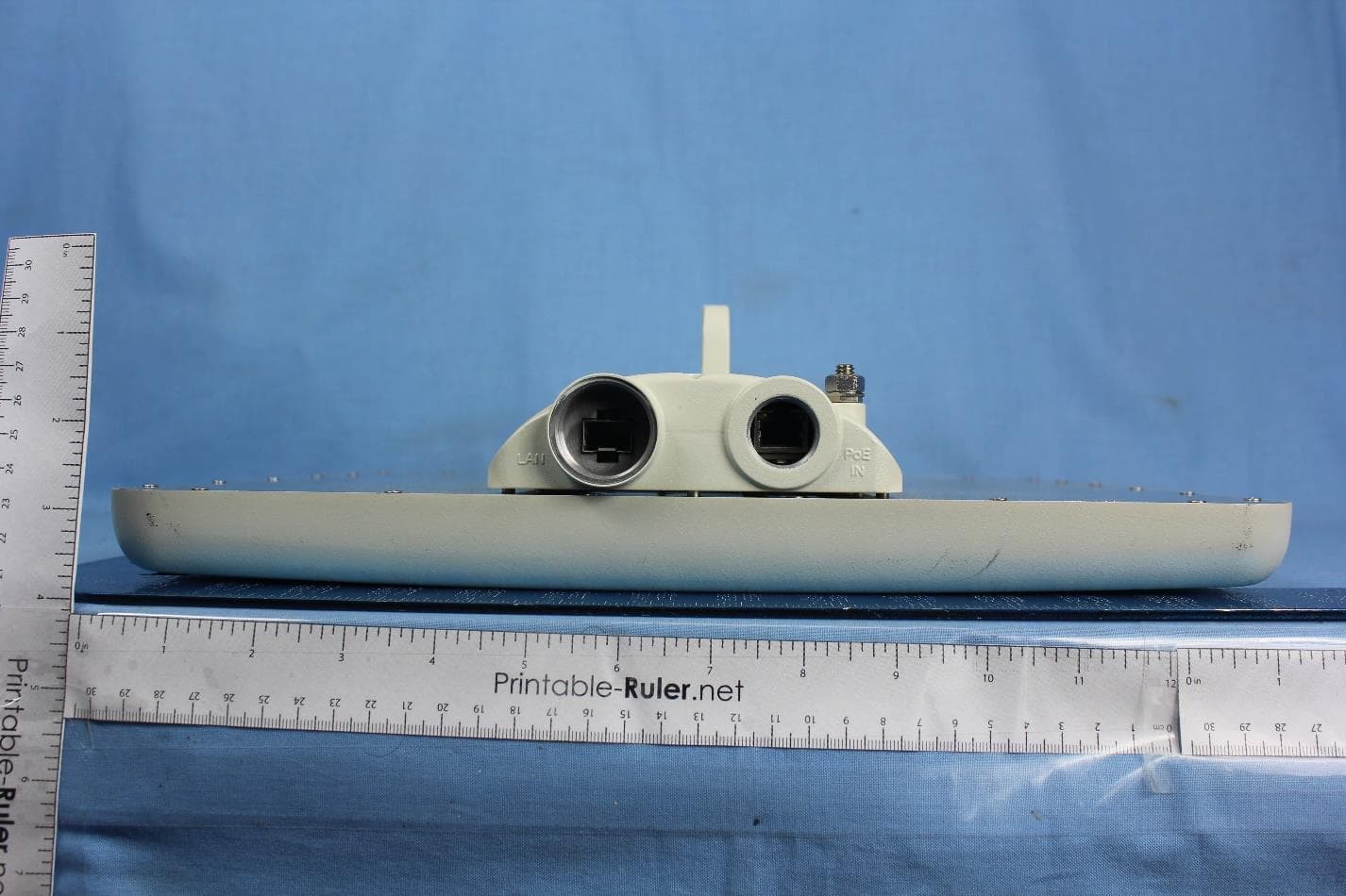
Radwin Ltd. FCC ID:Q3KRW2030 IC:5100A-RW2030 Page 1 of 6 EXTERNAL PHOTOGRAPHS This document contains 5 photographs Radwin Ltd. FCC ID:Q3KRW2030 IC:5100A-RW2030 Page 2 of 6 Photograph No.1 “RADWIN 2000 3 GHz band” front view Radwin Ltd. FCC ID:Q3KRW2030 IC:5100A-RW2030 Page 3 of 6 Photograph No.2 “RADWIN 2000 3 GHz band” rear side view Radwin Ltd. FCC ID:Q3KRW2030 IC:5100A-RW2030 Page 4 of 6 Photograph No.3 “RADWIN 2000 3 GHz band” side view with connectors Radwin Ltd. FCC ID:Q3KRW2030 IC:5100A-RW2030 Page 5 of 6 Photograph No.4 “RADWIN 2000 3 GHz band” front view with integral antenna Radwin Ltd. FCC ID:Q3KRW2030 IC:5100A-RW2030 Page 6 of 6 Photograph No.5 “RADWIN 2000 3 GHz band” rear side view with integral antenna
ID Label/Location Info
Radwin Ltd. FCC ID:Q3KRW2030 IC:5100A-RW2030 Page 1 of 2 Label with FCC ID: Q3KRW2030 and IC: 5100A-RW2030 Radwin Ltd. FCC ID:Q3KRW2030 IC:5100A-RW2030 Page 2 of 2 An outdoor radio terminal shall bear the label with FCC ID:Q3KRW2030 and IC:5100A-RW2030 on a front panel as shown in the photo below:
Operational Description
Product Highlights The RADWIN 1000 3GHz BAND, RADWIN 2000 3GHz BAND and RADWIN 3000 3GHz BAND are high-capacity carrier-grade radio devices, designed to meet the requirements of current and next generation markets and applications. The radio devices operate in the 3.5 and 3.65 GHz band and comply with the FCC and IC regulations. They feature software configurable antenna port activation enabling single (RADWIN 1000 3GHz BAND) or dual (RADWIN 2000 3GHz v) antenna port operation. Devices configured as RADWIN 2000 and RADWIN 3000 have the advanced air-interface based on MIMO, antenna diversity. The RADWIN 3000 3GHz BAND are software configured Point to Multipoint devices. • 130 Mbps Ethernet throughput and up to 16 E1s/T1s • Long range – up to 120 km/75 miles • Adaptive asymmetric throughput – dynamic allocation between uplink and downlink • Single radio supporting multiple bands (3.45 to 3.70 GHz) • Advanced MIMO, OFDM and Diversity technologies • Robust and reliable to operate in tough conditions, extreme temperatures and non line-of-sight scenarios • Ease of operation and maintenance RADWIN 1000 3GHz BAND RADWIN 2000 3GHz BAND RADWIN 3000 3GHz BAND Operational Description The RADWIN 1000 3GHz BAND, RADWIN 2000 3GHz BAND and RADWIN 3000 3GHz BAND product features: • Powered by 48VDC through an indoor unit (IDU) or PoE device. • The radio link is established within 1 minute after power applied to device. • Software controlled limitations determine the maximum transmission power permitted according to the FCC/IC regulations. • The radio device features up to 130 Mbps @ 20 MHz channel bandwidth (net throughput, full duplex) • The modulation technique used by the device is OFDM (BPSK/QPSK/16QAM/64QAM) • The antennas used for this device are 25 dBi dish, 21 dBi integral flat and 22 dBi external flat. • The external antennas are connected to the device via RF feeder cable. Product Specifications Configuration Architecture Outdoor Unit with Integrated Antenna or Connectorized for External Antenna IDU to ODU Interface Outdoor CAT-5e cable; Maximum cable length: 100 m Radio Capacity 130 Mbps throughput (up to 16 x E1s/T1s plus Ethernet) Range Up to 120 km / 75 miles Channel Bandwidth 5, 10, 20 MHz Modulation 2x2 MIMO-OFDM (BPSK/QPSK/16QAM/64QAM) Adaptive Modulation & Coding Supported Automatic Channel Selection Supported Diversity Supported Spectrum View Supported Max Tx Power 26 dBm (3.5 GHz band) 25.66 dBm (3.65 band @ 20MHz channel bandwidth) Duplex Technology TDD Error Correction FEC k = 1/2, 2/3, 3/4, 5/6 Encryption AES 128 Supported Indoor Units IDU-C IDU-E PoE device Supported Bands Band Occupied Frequency Range Radio Compliance 3.65 GHz 3.65- 3.70 GHz FCC 47CFR, Part 90, IC RSS 197, issue-1 3.5 GHz 3.475 - 3.650 GHz IC RSS 192, issue-3 Mechanical Dimensions 19.5(w) x 27.0(h) x 8.0(d) cm Weight 1.8 kg / 3.6 lbs Power Power Feeding Power provided over ODU-IDU cable Power Consumption <35W (IDU + ODU) Environmental Operating Temperatures -35°C ~ 60°C / -31°F – 140°F Humidity 100% condensing, IP67 (totally protected against dust and against immersion up to 1m) Safety FCC/IC (cTUVus) UL 60950-1, UL 60950-22, CAN/CSA C22.2 60950-1, CAN/CSA C22.2 60950-22 ETSI EN/IEC 60950-1, EN/IEC 60950-22 EMC FCC CFR47 Class B, Part15, Subpart B ETSI EN 300 386, EN 301 489-1, EN 301 489-4 CAN/CSA-CEI/IEC CISPR 22-04 Class B AS/NZS CISPR 22-2004 Class B ODU with Integrated Antenna Connectorized ODU for External Antenna
Operational Description
Subject: FCC/IC Certification of RADWIN 2000 3GHz BAND, RADWIN 1000 3GHz BAND and RADWIN 3000 3GHz BAND October 18, 2010 To whom it may concern, RADWIN Ltd wishes to market the RADWIN 2000 3GHz BAND, RADWIN 1000 3GHz BAND and RADWIN 3000 3GHz BAND radio devices, complying with FCC 47CFR, Part 90 at 3.650 - 3.700 GHz regulation. RADWIN 2000 3GHz BAND and RADWIN 1000 3GHz BAND are point-to-point radio links, consisting of two radio units, one at each end of the link, enabling wireless connectivity for either urban or rural deployments, supporting both access and backhaul applications, providing Ethernet and TDM data interfaces. RADWIN 3000 3GHz BAND is a point to multi-point system consisting one base station and several client units (CPEs), enabling wireless connectivity for either urban or rural deployments, supporting both access and backhaul applications, providing Ethernet and TDM data interfaces. RADWIN Ltd wishes to conform to FCC DA 07-4605 (November 14, 2007) FCC-certified equipment requirements: "Restricted contention protocols can prevent interference only with other devices incorporating the same or similar protocols. Equipment using a restricted protocol can operate only on the lower 25 megahertz (3650-3675 MHz)" The RADWIN 2000 3GHz BAND, RADWIN 1000 3GHz BAND and RADWIN 3000 3GHz BAND radio links are based on RADWIN TDD air protocol that meets the FCC definition of a “restricted” contention based protocol allowing co-channel operation minimizing mutual interferences, by incorporating the following mechanisms: 1. In-site and inter-site synchronization mechanism that synchronizes the transmission signal of several links avoiding mutual interferences between transmitted and received signals. RADWIN air interface synchronization mechanism used with a planning of the co- located links enable operation in a co-channel of more than one link preventing service interference. In-site synchronization mechanism is based on a RADWIN propriety protocol, when the inter-site synchronization mechanism integrates a GPS unit with RADWIN propriety air interface protocol 2. Automatic Channel Selection (ACS) mechanism that senses the interference level at the operating channel (co-channel interference). The ACS mechanism automatically switches to other channel in case of reaching a system threshold of interference level that impacts significantly the service provided by RADWIN radio links. Supporting frequency step of 1 MHz, the RADWIN ACS mechanism enables maximum spectrum efficiency and installation flexibility. 3. Support of various different RFD ("Radio Frame Duration") schemes that can be used to create a TDD offset in the transmission signal avoiding considerable high periods of interferences and minimizing its mutual-interference in a co-channel operation. 4. The method to permit occupancy to other RADWIN systems consists of: a. Reduce transmit time allowing other system to transmit b. Listen to the noise level of the other transmitting system in order to switch to other channel c. Allow TDD synchronization to reduce mutual interferences between the transmitting RADWIN systems 5. The action taken if two or more transmitters simultaneously access the same channel by the master and the client devices is as following: a. The case of TDD synchronization interference of other, near located unit, is avoided since the units are synchronized in transmit and receive TDD paths. b. The system changes the modulation automatically based on the interference level to enable a better performance in case of mutual interferences 6. The opportunities for other similar systems to operate are provided by: a. RADWIN selects the less interfered channel, by measuring the noise floor attribute, thus avoiding interference with other systems b. TDD synchronization allows working in co-channel scenario without mutual- interferences With the deployment of the above mechanisms RADWIN radio links enable a reasonable opportunity to operate in a co-channel under restricted mode. Best regards, Turgeman Eli VP Product Management RADWIN
RF Exposure Info
Radwin Ltd. FCC ID:Q3KRW2030 RF Exposure Evaluation according to FCC §1.1307 The transceiver is classified as fixed. The calculation was done to confirm a minimum safety distance. Limit for power density for general population/uncontrolled exposure is 1 mW/cm 2 (for 1500 –100,000 MHz frequency range). The power density P (mW/cm 2 ) = P T / 4 r 2 P T is the transmitted power, which is equal to the peak transmitter output power plus maximum antenna gain. The maximum equivalent isotropically radiated power EIRP was obtained in 3660-3665 MHz band: P T = 24.65 dBm +17 dBi = 41.65 dBm = 14621.8 mW, where 24.65 dBm is the EUT maximum output power; 17 dBi – antenna gain. The minimum safe distance “r”, where RF exposure does not exceed FCC permissible limit, is r = sqrt { P T / (Px4)} = sqrt {14621.8 / 12.56} = 34 cm. General public will not be exposed to dangerous RF level.
Test Report
Hermon Laboratories Ltd. Harakevet Industrial Zone, Binyamina 30500, Israel Tel. +972-4-6288001 Fax. +972-4-6288277 E-mail: [email protected] Page 1 of 263 Report ID: RDWRAD_FCC.20845R.doc Date of Issue: November 2010 Electrical 839.01 TEST REPORT ACCORDING TO: FCC CFR 47 PART 90 subpart Z; RSS-197 Issue 1:2010 FOR: RadWin Ltd. Outdoor radio unit operating in the 3.65 GHz band Models: RADWIN 1000 3GHz BAND, RADWIN 2000 3GHz BAND, RADWIN 3000 3GHz BAND This report is in conformity with ISO/ IEC 17025. The "A2LA Accredited" symbol endorsement applies only to the tests and calibrations that are listed in the scope of Hermon Laboratories accreditation. The test results relate only to the items tested. This test report shall not be reproduced in any form except in full with the written approval of Hermon Laboratories Ltd. D Report ID: RDWRAD_FCC.20845R.doc Date of Issue: November 2010 Page 2 of 263 Table of contents 1 Applicant information .........................................................................................................................................................3 2 Equipment under test attributes ........................................................................................................................................3 3 Manufacturer information ..................................................................................................................................................3 4 Test details ........................................................................................................................................................................3 5 Tests summary ..................................................................................................................................................................4 6 EUT description .................................................................................................................................................................5 6.1 General information ...........................................................................................................................................................5 6.2 Ports and lines ...................................................................................................................................................................5 6.3 Support and test equipment ..............................................................................................................................................5 6.4 Changes made in the EUT ................................................................................................................................................5 6.5 Test configuration ..............................................................................................................................................................6 6.6 Transmitter characteristics ................................................................................................................................................7 7 Transmitter tests according to 47CFR part 90 and RSS-197 issue 1 requirements ........................................................8 7.1 Maximum output power .....................................................................................................................................................8 7.2 Peak EIRP power density................................................................................................................................................89 7.3 Occupied bandwidth test .............................................................................................................................................. 130 7.4 Emission mask test for 17 dBi gain .............................................................................................................................. 132 7.5 Emission mask test for 13.5 dBi gain ........................................................................................................................... 139 7.6 Spurious emiss…
Text truncated - open the document above for the full version.
Contact Information
Applicant
Shlomo Weiss(Standardization Officer)
Technical Contact
Hermon Laboratories LtdMichael Nikishin
Harakevet Industrial Zone · Binyamina · Israel
Test Firm
Hermon Laboratories Ltd.Alexander Usoskin
Technical Specifications
| # | Rule Parts | Frequency Range | Power Output | Emission | Tolerance |
|---|---|---|---|---|---|
| 5 | 9 | 3.66 GHz - 3.66 GHz | 8.97 W | 20MOW7W | 24735 Hz |
Other Applications from Radwin Ltd.
Q3K-PTP5GAX
Feb 25, 20235 GHz High Performance PtP Outdoor Unit
Equipment Class
NII - Unlicensed National Information Infrastructure TX
Q3K-NEO5X
Apr 27, 2021Single Carrier 5.x GHz Base Station with Beamforming Antenna, Dual Carrier 5.x GHz Base Station with Beamforming Antenna
Equipment Class
NII - Unlicensed National Information Infrastructure TX
Q3K-5XSUALMOD
Apr 13, 20215 GHz SU/Alpha Board
Equipment Class
NII - Unlicensed National Information Infrastructure TX
Q3K-5XACMODMS
Sep 13, 20205 GHz MS RF Module
Equipment Class
NII - Unlicensed National Information Infrastructure TX
Q3K-TRBR600G
Aug 25, 2020Point to point/point to multipoint 57-71 GHz radio transceiver
Equipment Class
DXX - Part 15 Low Power Communication Device Transmitter