Q3KRW2054Outdoor radio unit operating in 5.3/5.4 GHz band
Radwin Ltd.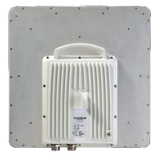
Click to zoom
Application Details
- Equipment Class
- NII - Unlicensed National Information Infrastructure TX
- Date of Grant
- Feb 25, 2009
- Application Purpose
- Original Equipment
- Date of Application
- Jan 21, 2009
- Equipment Note
- Outdoor radio unit operating in 5.3/5.4 GHz band
- Frequency Range
- 5480.00000000 - 5715.00000000
- Company
- Radwin Ltd.
- Country
- Israel
Documents & Files
Document Text
Text extracted from the exhibit documents filed with the FCC. Open a document above to read the original.
Users Manual
RADWIN 1000/2000 User ManualVersion 2.2a5-1 Chapter 5 Configuring the Link This chapter describes the link configuration procedure, which is performed after the installation of both sides of the RADWIN 1000/2000 link, as set out in chapters 3 and 4. Link configuration uses a Link Configuration Wizard to redefine the configu- ration parameters and fine-tune an operational link. Both sides of the link are configured simultaneously. The following parameters are configured using the Link Configuration Wiz- ard: • System parameters • Channel settings • Transmission power and antenna settings •Service parameters Link Configuration: Getting Started The Main Window of the RADWIN Manager Ensure that the RADWIN Manager is running. The main window should look similar to that in figure 5-1: The RADWIN Manager Toolbar Chapter 5 RADWIN 1000/2000 User ManualVersion 2.2a5-2 . Figure 5-1: Main window, Wireless Link is Active Before starting a configuration session, make sure that a communication link exists between the two sides of the link. The Link Status indication bar must be green. In the Link Status panel, the Status field should show Link Active in green. The main window of the RADWIN Manager contains a large amount of information about the link. Before proceeding to details of link configuration we set out the meaning of each item in the main window. The RADWIN Manager Toolbar In configuration mode, the RADWIN Manager toolbar contains the following buttons: The RADWIN Manager Main Menu Chapter 5 RADWIN 1000/2000 User ManualVersion 2.2a5-3 The RADWIN Manager Main Menu The RADWIN Manager menu, is shown in table 5-2 below: Table 5-1: RADWIN Manager Toolbar ItemDescription Link ConfigurationChanges configuration parameters of an operating wireless link; assigns text files for storing alarms, statistics and configuration data. This button is disabled until a link installation has been completed Link InstallationPerforms preliminary configuration of the system. This button is disabled after the link is installed Site: <Site 1 name>Opens the Site configuration dialog for Site A. Same as Configuration | 1 Configure <Site 1 name> Site: <Site 2 name>Opens the Site configuration dialog for Site B. Same as Configuration | 2 Configure <Site 2 name> Get Diagnostics Obtain system information Clear CountersDisabled Log offCloses the current session and logs off RADWIN Manager ExitExits RADWIN Manager The RADWIN Manager Main Menu Chapter 5 RADWIN 1000/2000 User ManualVersion 2.2a5-4 Table 5-2: RADWIN Manager main menu functionality Menu level FunctionReference Top+1+2 File Log OffReturn to Log On dialog. Same as Log Off button ExitExit the manager. Same as Exit button Configuration Link Configuration Run the Configuration Wiz- ard. Not available in installation mode 1 Configure <Site 1 name> Provides limited configura- tion for site. Has a path to return to installation mode 2 Configure <Site 2 name> Provides limited configura- tion for site. Has a path to return to installation mode InstallationRuns the Installation Wiz- ard. Not available in configuration mode Tools Performance Monitoring Report Active Alarms 1 <Site 1 name>Shows active alarms for <Site 1 name> 2 <Site 2 name>Shows active alarms for <Site 1 name> Change Password Change the Log On pass- word dialog page 4-7 Events Log page 7-10 Clear EventsClear local events log Save to FileSave events log file PreferencesLocal preferences dialog The RADWIN Manager Main Menu Chapter 5 RADWIN 1000/2000 User ManualVersion 2.2a5-5 Maintenance Clear countersDisabled LoopbacksDisabled Reset 1 <Site 1 name>Reset <Site 1 name> ODU 2 <Site 2 name>Reset <Site 2 name> ODU Help RADWIN Manager Help View online version of the User Manual Link Budget Calculator Calculator opened in default browser Appendix D Get Diagnostics Information Obtain system information page 7-1 About RADWIN Manager Manager build and system information Table 5-2: RADWIN Manager main menu functionality (Continued) Menu level FunctionReference Top+1+2 Elements of the RADWIN Manager Main Window Chapter 5 RADWIN 1000/2000 User ManualVersion 2.2a5-6 Elements of the RADWIN Manager Main Window Link details pane The Link details pane on the left is split into three sections. The top section summarizes information about the link: The two lower panels show basic link site details: Table 5-3: Link Details Item Link ID Services selected Frequency Channel bandwidth Rate Link status Elements of the RADWIN Manager Main Window Chapter 5 RADWIN 1000/2000 User ManualVersion 2.2a5-7 Monitor pane he monitor pane, is the main source of real time information about link per- formance at both link sites. It includes the following panes (top to bottom): • Radio Interface, Received Signal Strength (RSS) in dBm • Ethernet Service: • Ethernet Throughput: The numbers are the current calculated throughputs at each site. The colored bars (with numbers) indi- cate the maximum possible throughput having regard for air conditions. • Rx and Tx Rates: Actual Ethernet traffic received and transmit- ted rates per site, in Mbps of Fbps. Table 5-4: Link site details, Site A and Site B Item IP Address Subnet Mask Trap Desalination Elements of the RADWIN Manager Main Window Chapter 5 RADWIN 1000/2000 User ManualVersion 2.2a5-8 Figure 5-2: Ethernet Bandwidth Indication • Frequency box: It shows the link frequency. The color of the box indicates the status •Green is an active link •Red is an inactive link •Magenta shows an authentication or compatibility problem •Brown shows severe compatibility problem Events Log The Events Log, stores alarms generated from both sides of the link and is detailed in chapter 7, The Events Log. Elements of the RADWIN Manager Main Window Chapter 5 RADWIN 1000/2000 User ManualVersion 2.2a5-9 Status Bar The Status bar, displays the following icons: Table 5-5: Status bar indicators Icon or LabelPurpose ConnectivityShows if RADWIN Manager is communicating with the ODU. Connection available Connection mode to the ODU •…
Text truncated - open the document above for the full version.
Attestation Statements
January 7, 2009 FCC Part 15 section 15.407 statement Radwin’s product that bears the FCC ID: Q3KRW2054 includes a mechanism that discontinues the transmission as required by FCC Part 15 section 15.407. Description: The system works in a fixed timing in which every radio frame is up to 650μs. Each radio frame contains both control and user data. The control size is fixed and less the 2% of the overall time. Transmission of radio frame contains user data if there is information to be transmitted. The size of the user data varies from 0 to maximum frame size. Itai Rubinstein Engineering Dept. Manager Radwin Ltd.
Attestation Statements
December 29, 2008 Professional Installation RADWIN ensures that the device FCC ID: Q3KRW2054 is limited to professional installation, by the following: 1. Marketing The device is not sold retail to the general public or by mail order. RADWIN sells the device only to its carefully selected certified distributors. 2. Professional installation The device must be installed and controlled by specially trained professionals. RADWIN provides all its distributors with training seminars which focus on installation and maintenance and officially certifies personnel who pass RADWIN training to perform installation and maintenance. The installation requires knowledge in radio equipment handling and technical knowledge concerned with operation of RADWIN's device. Installation guidelines must be followed to ensure proper operation of the device. 3. Application The intended use is generally not for the general public. It is generally for industry/commercial use. RADWIN's end-users include cellular and fixed carriers, telecom/internet service providers and IT departments of utility companies and enterprises. Itai Rubinstein Engineering Dept Manager, Radwin Ltd.
Cover Letter(s)
RADWIN Ltd. 32 Habarzel St Tel-Aviv, 69710, Israel, Tel- 972-3-766-2903, Fax-972-3-766-2922 January 7, 2009 Nemko Canada Inc. 303 River Road Ottawa, Ontario, Canada K1V 1H2 Attn: Mr. Stuart Beck, Director of Certification Subject: Application for certification of an outdoor radio unit operating in 5.3/5.4 GHz band, FCC ID:Q3KRW2054 Dear Gentlemen, Please find attached our application for certification of an outdoor radio unit operating in 5.3/5.4 GHz band, model names RADWIN 1000 and RADWIN 2000, FCC ID: Q3KRW2054, prepared in accordance with FCC Rules, part 15 subpart E. The product testing and this application for certification were performed by Hermon Laboratories, which is listed by FCC, Registration Numbers 90623, 90624. Hermon Labs responsible person is Mr. Michael Nikishin, tel: 011 972 4626 8440, fax:011 972 4628 8277, e-mail: [email protected]. Sincerely yours, Itai Rubinstein Engineering department manager Radwin Ltd
External Photos
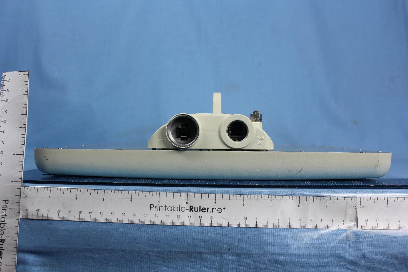
Radwin Ltd. FCC ID:Q3KRW2054 IC:5100A-RW2054 Page 1 of 9 EXTERNAL PHOTOGRAPHS This document contains 8 photographs Radwin Ltd. FCC ID:Q3KRW2054 IC:5100A-RW2054 Page 2 of 9 Photograph No.1 RADWIN 2000 front view Radwin Ltd. FCC ID:Q3KRW2054 IC:5100A-RW2054 Page 3 of 9 Photograph No.2 RADWIN 1000 front view Radwin Ltd. FCC ID:Q3KRW2054 IC:5100A-RW2054 Page 4 of 9 Photograph No.3 RADWIN 2000 rear side view Radwin Ltd. FCC ID:Q3KRW2054 IC:5100A-RW2054 Page 5 of 9 Photograph No.4 RADWIN 1000 rear side view Radwin Ltd. FCC ID:Q3KRW2054 IC:5100A-RW2054 Page 6 of 9 Photograph No.5 RADWIN 2000 side view with connectors Radwin Ltd. FCC ID:Q3KRW2054 IC:5100A-RW2054 Page 7 of 9 Photograph No.6 RADWIN 1000 side view with connectors Radwin Ltd. FCC ID:Q3KRW2054 IC:5100A-RW2054 Page 8 of 9 Photograph No.7 RADWIN 1000/2000 front view with integral antenna Radwin Ltd. FCC ID:Q3KRW2054 IC:5100A-RW2054 Page 9 of 9 Photograph No.8 RADWIN 2000 rear side view with integral antenna
Operational Description
RADWIN 1000/2000 January 2009 RADWIN 1000, RADWIN 2000 Product Description ODU with Integrated Antenna Connectorized ODU for External Antenna The RADWIN 1000/2000 is a high-capacity carrier-grade radio device, designed to meet the requirements of current and next generation markets and applications. The RADWIN 1000/2000 radio device operates in the 5.3 and 5.4 GHz band and complies with the FCC and IC regulations. RADWIN 1000/2000 also features software configurable antenna port activation enabling single (RADWIN 1000) or dual (RADWIN 2000) antenna port operation. The device configured as RADWIN 2000 has the advanced air-interface based on MIMO, antenna diversity. RADWIN 1000/2000 January 2009 Operational Description The RADWIN 1000/2000 product features: • The RADWIN 1000/2000 is powered by 48VDC through an indoor unit (IDU-C or PoE device). • The radio link is established within 1 minute after power applied to device. • Software controlled limitations determine the maximum transmission power permitted according to the FCC/IC regulations. • The radio device features up to 130 Mbps @ 20 MHz channel bandwidth (net throughput, full duplex) • The modulation technique used by the device is OFDM (BPSK/QPSK/16QAM/64QAM) • The antennas used for this device are 28 dBi dish, 23.5 dBi integral flat and 22.5 dBi external flat RADWIN 1000/2000 January 2009 Product Specifications Configuration Architecture Outdoor Unit with Integrated Antenna or Connectorized for External Antenna IDU to ODU Interface Outdoor CAT-5e cable; Maximum cable length: 100 m Radio Capacity 130 Mbps @ 20 MHz channel bandwidth (net throughput, full duplex) Range Up to 120 km / 75 miles Frequency Bands Regulations FCC / IC FCC / IC Band 5.250 – 5.350 GHz 5.470 – 5.725 GHz Channel Bandwidth 5, 10, 20 MHz Modulation OFDM (BPSK/QPSK/16QAM/64QAM) Adaptive Modulation & Coding Supported Automatic Channel Selection Supported Max Tx Power Max Tx Power Antenna 1.9 dBm 28 dBi Dish 6.5 dBm 23.5 dBi Integral 7.5 dBm 22.5 dBi External Duplex Technology TDD Error Correction FEC k = 1/2, 2/3, 3/4, 5/6 Encryption AES 128 Mechanics Dimensions ODU with Integrated Antenna: 37.1(w) x 37.1(h) x 10.0(d) cm ODU Connectorized: 19.0(w) x 27.0(h) x 7.0(d) cm Weight ODU with Integrated Antenna: 3.5 kg / 7 lbs ODU Connectorized: 1.8 kg / 3.6 lbs Power Power Feeding PoE -48 VDC Power Consumption <35W (IDU + ODU) Environmental Operating Temperatures -35°C - +60°C / -31°F – 140°F Humidity Up to 100% non-condensing, IP67 Safety FCC/IC (cTUVus) UL 60950-1, CAN/CSA 60950-1 C22.2 ETSI EN/IEC 60950-1 EMC FCC CFR47 Class B, Part15, Subpart B ETSI EN 300 386 (2005), EN 301 489-4 (2002) CAN/CSA-CEI/IEC CISPR 22-04 Class B AS/NZS CISPR 22-2004 Class B
Operational Description
September 2008 RW-9611-4958INT RADWIN Antenna Specifications RW-9611-4958INT 4.9-6.0 GHz Gain 22.5dBi Dual Polarization Flat Panel Electrical Frequency Range 4.9-6.0 GHz Minimum Peak Gain Port H 18.5 dBi @ 4.9-5.0 GHz 19.5 dBi @ 5.0-5.15 GHz 22.5 dBi ± 0.5 @ 5.15-6.0 GHz Port V 21.0 dBi @ 4.9-5.0 GHz 22 dBi @ 5.0-5.15 GHz 23.5 dBi @ 5.15-5.725 GHz 24 dBi @ 5.725-6.0 GHz VSWR 1.5 : 1 (typ) 1.7 : 1 (max) 3 dB Beamwidth 8° (typ) AZ & EL Beam Squint ± 2° Port V & Port H Polarization Dual Linear (Vertical and Horizontal) Sidelobes Level ETSI EN 302 085 V1.1.2, TS1-TS3 Cross Polarization ETSI EN 302 085 V1.1.2, TS1-TS3 F/B Ratio -35 dB (max) Port To Port Isolation -40 dB (min) Input Impedance 50 (ohm) Input Power 6W (max) Lightning Protection DC grounded Mechanical Dimensions (L x W x H) 371 x 371 x 40mm (max) Weight 2.0 kg (max) Connector Two cables double shielded RD-316 with MMCX right angle length 15cm Radome Plastic Base Plate Aluminum with chemical conversion coating Environmental Temperature -45°C to +70°C (IEC 68-2-1, IEC 68-2-2, IEC 68-2-14) Humidity Up to 95% (ETSI EN300-2-4, T4.1E) Water Tightness IEC 529 - IP67 (when the antenna installed on the radio enclosure) Flammability UL 94 - class HB Solar Radiation ASTM G53 Salt Spray IEC 68-2-11 Ka Ice and Snow Up to 25mm Wind Speed Survival 220 Km/h Operation 160 Km/h Wind Load (Survival) Front Thrust 39.6 kg Side Thrust 4.3 kg Regulatory Compliance ETSI EN 302 326-3 V1.1.2. (2006-03) RoHS , CE 0682
Operational Description
September 2008 RW-9611-4958 RADWIN Antenna Specifications RW-9611-4958 4.9-5.875 GHz Gain 23dBi Dual Polarization Flat Panel Electrical Frequency Range 4.9-5.875 GHz Minimum Peak Gain 22.5 dBi ± 0.5 @ 4.9-5.25 GHz 23 dBi ± 0.5 @ 5.25-5.875 GHz VSWR 1.5 : 1 (typ) 1.7 : 1 (max) 3 dB Beamwidth 9° (typ) AZ & EL Beam Squint ± 2° Port V & Port H Polarization Dual Linear (Vertical and Horizontal) Sidelobes Level ETSI EN 302 085 V1.1.2, TS1-TS3 Cross Polarization ETSI EN 302 085 V1.1.2, TS1-TS3 F/B Ratio -35 dB (max) Port To Port Isolation 40 dB (min) Input Impedance 50 (ohm) Input Power 10W (max) Lightning Protection DC grounded Mechanical Dimensions (L x W x H) 371 x 371 x 40mm (max) Weight 2.5 kg (max) Connector Two N type female Radome Plastic Base Plate Aluminum with chemical conversion coating Mounting Kit Standard Environmental Temperature -45°C to +70°C (IEC 68-2-1, IEC 68-2-2, IEC 68-2-14) Humidity Up to 95% (ETSI EN300-2-4, T4.1E) Water Tightness IEC 529 - IP67 Flammability UL 94 - class HB Solar Radiation ASTM G53 Salt Spray IEC 68-2-11 Ice and Snow Up to 25mm Wind Speed Survival 220 Km/h Operation 160 Km/h Wind Load (Survival) Front Thrust 39.6 kg Side Thrust 4.3 kg Regulatory Compliance ETSI EN 302 326-3 V1.1.2. (2006-03) RoHS , CE 0682
Operational Description
September 2008 RW-9721-5158 RADWIN Antenna Specifications RW-9721-5158 5.150-5.875 GHz Gain 28dBi Dual Polarization Parabolic Dish Electrical Frequency Range 5.150-5.875 GHz Minimum Peak Gain Low band 28 dBi Mid band 28.4 dBi High band 28.9 dBi VSWR 1.4 : 1 3 dB Beamwidth 5.6° Polarization Dual Linear (Vertical and Horizontal) Cross Polarization 28 dB F/B Ratio 35 dB Input Impedance 50 (ohm) Mechanical Diameter 2 ft Weight 20.4 kg (max) Connector Two N type female
RF Exposure Info
Radwin Ltd. FCC ID:Q3KRW2054 RF Exposure Evaluation according to §15.407(f) and §1.1307 The transceiver is classified as fixed. The calculation was done for minimum safety distance. The device operating frequency ranges are 5250 - 5350 MHz, 5480 – 5715 MHz. Limit for power density for general population/uncontrolled exposure is 1 mW/cm 2 (for 1500 –100,000 MHz frequency range). The power density P (mW/cm 2 ) = P T / 4π ππ π r 2 P T is the transmitted power, which is equal to the peak transmitter output power plus maximum antenna gain. The maximum equivalent isotropically radiated power EIRP is P T = 7.5 dBm +22.5 dBi = 30 dBm = 1000 mW, where 7.5 dBm is the EUT maximum output power in 5250 - 5350 MHz range and external antenna, 22.5 dBi – antenna assembly gain. The minimum safe distance “r”, where RF exposure does not exceed FCC permissible limit, is r = sqrt { P T / (Px4π)} = sqrt {1000/ 12.56} = 8.9 cm. General public cannot be exposed to dangerous RF level.
Test Report
Hermon Laboratories Ltd. P.O.Box 23, Binyamina 30500, Israel Tel. +972 4628 8001 Fax. +972 4628 8277 E-mail: [email protected] Page 1 of 196 Report ID: RDWRAD_FCC.19240.doc Date of Issue: January 2009 Electrical 839.01 TEST REPORT ACCORDING TO: FCC part 15 subpart E and RSS-210 Issue 7, Annex 9 FOR: RadWin Ltd. Outdoor radio unit operating in the 5.3 GHz band Model:RADWIN 1000, RADWIN 2000 This report is in conformity with ISO/ IEC 17025. The "A2LA Accredited" symbol endorsement applies only to the tests and calibrations that are listed in the scope of Hermon Laboratories accreditation. The test results relate only to the items tested. This test report shall not be reproduced in any form except in full with the written approval of Hermon Laboratories Ltd. Report ID: RDWRAD_FCC.19240.doc Date of Issue: January 2009 Page 2 of 196 Table of contents 1 Applicant information..................................................................................................................................................... 3 2 Equipment under test attributes .................................................................................................................................... 3 3 Manufacturer information .............................................................................................................................................. 3 4 Test details.................................................................................................................................................................... 3 5 Tests summary.............................................................................................................................................................. 4 6 EUT description............................................................................................................................................................. 5 6.1 General information....................................................................................................................................................... 5 6.2 Ports and lines .............................................................................................................................................................. 5 6.3 Support and test equipment .......................................................................................................................................... 5 6.4 Changes made in the EUT ............................................................................................................................................ 5 6.5 Test configuration.......................................................................................................................................................... 6 6.6 Transmitter characteristics ............................................................................................................................................ 7 7 Transmitter tests according to 47CFR part 15 subpart E and RSS-210 Annex 9 requirements .................................... 8 7.1 Peak output power and peak spectral power density .................................................................................................... 8 7.2 Ratio of the peak excursion of the modulation envelope to the peak transmit power .................................................. 67 7.3 Field strength of spurious emissions ........................................................................................................................... 88 7.4 Band edge spurious emission measurements........................................................................................................... 135 7.5 Frequency stability test.............................................................................................................................................. 165 7.6 Antenna requirements ............................................................................................................................................... 169 7.7 Conducted emissions ................................................................................................................................................ 170 7.8 Receiver radiated spurious emission measurements ................................................................................................ 173 8 APPENDIX A Test equipment and ancillaries used for tests..................................................................................... 182 9 APPENDIX B Measurement uncertainties................................................................................................................. 184 10 APPENDIX C Test laboratory description ................................................................................................................. 185 11 APPENDIX D Specification references ..................................................................................................................... 185 12 APPENDIX E Test equipment correction factors....................................................................................................... 186 13 APPENDIX F Abbreviations and acronyms............................................................................................................... 196 Report ID: RDWRAD_FCC.19240.doc Date of Issue: January 2009 Page 3 of 196 1 Applicant information Client name: RadWin Ltd. Address: 32 Habarzel str., Tel Aviv, Israel, 69710 Telephone: +972 3766 2988 Fax: +972 3766 2922 E-mail: [email protected] Contact name: Mr. Shlomo Weiss 2 Equipment under test attributes Product name: Outdoor radio unit operating in 5.3 GHz band Product type: Point to point transceiver Model(s): RADWIN 2000 Receipt date 12/18/2008 3 Manufacturer information Manufacturer name: RadWin Ltd. Address: 32 Habarzel str., Tel Aviv, Israel, 69710 Telephone: +972 3766 2988 Fax: +972 3766 2922 E-Mail: [email protected] Contact name: Mr. Shlomo…
Text truncated - open the document above for the full version.
Test Report
Hermon Laboratories Ltd. P.O.Box 23, Binyamina 30500, Israel Tel. +972 4628 8001 Fax. +972 4628 8277 E-mail: [email protected] Page 1 of 262 Report ID: RDWRAD_FCC.19241.doc Date of Issue: December 2008 Electrical 839.01 TEST REPORT ACCORDING TO: FCC part 15 subpart E and RSS-210 Issue 7, Annex 9 FOR: RadWin Ltd. Outdoor radio unit operating in the 5.4 GHz band Model:RADWIN 1000, RADWIN 2000 This report is in conformity with ISO/ IEC 17025. The "A2LA Accredited" symbol endorsement applies only to the tests and calibrations that are listed in the scope of Hermon Laboratories accreditation. The test results relate only to the items tested. This test report shall not be reproduced in any form except in full with the written approval of Hermon Laboratories Ltd. Report ID: RDWRAD_FCC.19241.doc Date of Issue: December 2008 Page 2 of 262 Table of contents 1 Applicant information..................................................................................................................................................... 3 2 Equipment under test attributes .................................................................................................................................... 3 3 Manufacturer information .............................................................................................................................................. 3 4 Test details.................................................................................................................................................................... 3 5 Tests summary.............................................................................................................................................................. 4 6 EUT description............................................................................................................................................................. 5 6.1 General information....................................................................................................................................................... 5 6.2 Ports and lines .............................................................................................................................................................. 5 6.3 Support and test equipment .......................................................................................................................................... 5 6.4 Changes made in the EUT ............................................................................................................................................ 5 6.5 Test configuration.......................................................................................................................................................... 6 6.6 Transmitter characteristics ............................................................................................................................................ 7 7 Transmitter tests according to 47CFR part 15 subpart E and RSS-210 Annex 9 requirements .................................... 8 7.1 Peak output power and peak spectral power density .................................................................................................... 8 7.2 Ratio of the peak excursion of the modulation envelope to the peak transmit power .................................................. 85 7.3 Field strength of spurious emissions ......................................................................................................................... 112 7.4 Conducted spurious emission measurements........................................................................................................... 178 7.5 Frequency stability test.............................................................................................................................................. 211 7.6 Antenna requirements ............................................................................................................................................... 238 7.7 Conducted emissions ................................................................................................................................................ 239 7.8 Receiver radiated spurious emission measurements ................................................................................................ 242 8 APPENDIX A Test equipment and ancillaries used for tests..................................................................................... 251 9 APPENDIX B Measurement uncertainties................................................................................................................. 252 10 APPENDIX C Test laboratory description ................................................................................................................. 253 11 APPENDIX D Specification references ..................................................................................................................... 253 12 APPENDIX E Test equipment correction factors....................................................................................................... 254 13 APPENDIX F Abbreviations and acronyms............................................................................................................... 262 Report ID: RDWRAD_FCC.19241.doc Date of Issue: December 2008 Page 3 of 262 1 Applicant information Client name: RadWin Ltd. Address: 32 Habarzel str., Tel Aviv, Israel, 69710 Telephone: +972 3766 2988 Fax: +972 3766 2922 E-mail: [email protected] Contact name: Mr. Shlomo Weiss 2 Equipment under test attributes Product name: Outdoor radio unit operating in 5.4 GHz band Product type: Point to point transceiver Model(s): RADWIN 2000 Receipt date 11/25/2008 3 Manufacturer information Manufacturer name: RadWin Ltd. Address: 32 Habarzel str., Tel Aviv, Israel, 69710 Telephone: +972 3766 2988 Fax: +972 3766 2922 E-Mail: [email protected] Contact name: Mr. Shlo…
Text truncated - open the document above for the full version.
Test Report
Report ID: RDWRAD_FCC.19241.doc Date of Issue: December 2008 Test specification: FCC section 15.407(b), RSS-210 Annex 9, section A9.3 Conducted emissions at band edges Test procedure: Public notice DA 00-705 / ANSI C63.4, Section 13.1.4 Test mode: Compliance Date: 11/23/2008 Verdict: PASS Temperature: 22∫C Air Pressure: 1007 hPa Relative Humidity: 42 % Power Supply: 120 VAC Remarks: Page 178 of 262 7.4 Conducted spurious emission measurements at band edges 7.4.1 General This test was performed to measure conducted spurious emissions from the EUT near the band edges and within the pass band of the antenna. Specification test limits are given in Table 7.4.1. Table 7.4.1 Spurious emission test limits Assigned frequency range, MHz EIRP of spurious, dBm/MHz Antenna assembly gain, dBi Resolution bandwidth, kHz 5470 - 5725 -27 22.5 1000 5470 - 5725 -27 28 1000 7.4.2 Test procedure 7.4.2.1 The EUT was set up as shown in Figure 7.4.1, energized normally modulated at the maximum data rate and its proper operation was checked. 7.4.2.2 The EUT was adjusted to produce maximum available to end user RF output power at the lowest carrier frequency. 7.4.2.3 The spectrum analyzer span was set to capture the carrier frequency and associated modulation products. The resolution bandwidth was set to 1 MHz. 7.4.2.4 The spectrum analyzer was set in max hold mode and allowed trace to stabilize. The highest em…
Text truncated - open the document above for the full version.
Contact Information
Applicant
Shlomo Weiss(Standardization Officer)
Technical Contact
Hermon Laboratories Ltd.Michael Nikishin
[email protected]+972 4626 8440
Harakevet Industrial zone · Binyamina · Israel
Non-Technical Contact
Radwin Ltd.Itai Rubinstein
[email protected]+972 3766 2928
Test Firm
Hermon Laboratories Ltd.Alexander Usoskin
Technical Specifications
| # | Rule Parts | Frequency Range | Power Output |
|---|---|---|---|
| 2 | 15E | 5.48 GHz - 5.71 GHz | 5.30 mW |
Other Applications from Radwin Ltd.
Q3K-PTP5GAX
Feb 25, 20235 GHz High Performance PtP Outdoor Unit
Equipment Class
NII - Unlicensed National Information Infrastructure TX
Q3K-NEO5X
Apr 27, 2021Single Carrier 5.x GHz Base Station with Beamforming Antenna, Dual Carrier 5.x GHz Base Station with Beamforming Antenna
Equipment Class
NII - Unlicensed National Information Infrastructure TX
Q3K-5XSUALMOD
Apr 13, 20215 GHz SU/Alpha Board
Equipment Class
NII - Unlicensed National Information Infrastructure TX
Q3K-5XACMODMS
Sep 13, 20205 GHz MS RF Module
Equipment Class
NII - Unlicensed National Information Infrastructure TX
Q3K-TRBR600G
Aug 25, 2020Point to point/point to multipoint 57-71 GHz radio transceiver
Equipment Class
DXX - Part 15 Low Power Communication Device Transmitter