Q3KRW2058UOutdoor radio unit operating in 5.8 GHz bands
Radwin Ltd.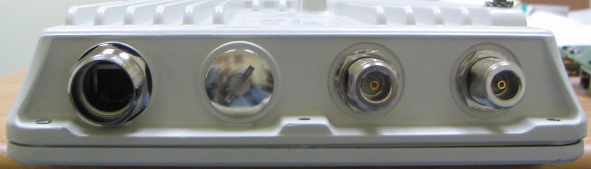
Click to zoom
Application Details
- Equipment Class
- NII - Unlicensed National Information Infrastructure TX
- Date of Grant
- Jul 21, 2010
- Application Purpose
- Original Equipment
- Date of Application
- Jun 27, 2010
- Equipment Note
- Outdoor radio unit operating in 5.8 GHz bands
- Frequency Range
- 5745.00000000 - 5805.00000000
- Company
- Radwin Ltd.
- Country
- Israel
Documents & Files
Document Text
Text extracted from the exhibit documents filed with the FCC. Open a document above to read the original.
Users Manual
UM 2000-25/05.10 RADWIN 1000/2000 Broadband Wireless Transmission System User Manual Version 2.5p-4 RADWIN 1000/2000 User ManualVersion 2.5p-4i RADWIN 1000/2000 User Manual Notice This manual contains information that is proprietary to RADWIN Ltd. (RADWIN hereafter). No part of this publication may be reproduced in any form whatsoever without prior written approval by RADWIN. Right, title and interest, all information, copyrights, patents, know-how, trade secrets and other intellectual property or other proprietary rights relating to this manual and to the RADWIN products and any software components contained therein are proprietary products of RADWIN protected under international copyright law and shall be and remain solely with RADWIN. The RADWIN name is a registered trademark of RADWIN Ltd. No right, license, or interest to such trademark is granted hereunder, and you agree that no such right, license, or interest shall be asserted by you with respect to such trademark. You shall not copy, reverse compile or reverse assemble all or any portion of the User Manual or any other RADWIN documentation or products. You are prohibited from, and shall not, directly or indirectly, develop, market, distribute, license, or sell any product that supports substantially similar functionality based or derived in any way from RADWIN products.Your undertaking in this paragraph shall survive the termination of this Agreement. This Agreement is effective upon your opening of a RADWIN product package and shall continue until terminated. RADWIN may terminate this Agreement upon the breach by you of any term thereof. Upon such termination by RADWIN, you agree to return to RADWIN any RADWIN products and documentation and all copies and portions thereof. For further information contact RADWIN at the address below or contact your local distributor. Disclaimer The parameters quoted in this document must be specifically confirmed in writing before they become applicable to any particular order or contract. RADWIN reserves the right to make alterations or amendments to the detail specification at its discretion. The publication of information in this document does not imply freedom from patent or other rights of RADWIN, or others. RADWIN 1000/2000 User ManualVersion 2.5p-4ii RADWIN Worldwide Offices For technical support contact: [email protected] For technical support in India only, contact: [email protected] For sales support contact: [email protected] Website: www.radwin.com Corporate Headquarters 27 Habarzel Street Tel Aviv, 69710 Israel Tel: +972 3 766 2917 Support Headquarter 27 Habarzel Street Tel Aviv, 69710 Israel Tel: +972 3 766 2900 Mobile: +972 54 766 0044 RADWIN North America 900 Corporate Drive Mahwah, NJ 07430 USA Tel (1): 1 800 444 7234 / 341 Tel (2): +1 201 529 1100 / 341 Latin America Headquarters Rua Grao Mogol 828 Belo Horizonte, MG 30310-010 Brazil Tel (1): +55 31 919 76 402 Tel (2): +972 54 758 6808 India Headquarters Mohan Co-operative Industrial Estate E-13, B-1 Extn New Delhi, 110044 India Tel: +91 11 4053 9180 APAC Headquarters 1 Jalan Kuala #13-01 The Morningside, 239639 Singapore Tel: +65 9878 3004 Indonesia Sales Office Jl. Jenderal Sudirman Kav. 86 Jakarta, 10220 Indonesia Tel: +62 8138 570 0657 Philippines Sales Office 37A. A luna St. West Rembo Makati City, 1200 Philippines Tel: +63 2882 6886 Mobile: +63 91 789 23427 China Sales Office Asian Games Village Huiyuan Gongyu J1312 Beijing 100101 China Tel: +86 010 8498 0629 RADWIN 1000/2000 User ManualVersion 2.5p-4iii Regulatory Compliance General Note This system has achieved Type Approval in various countries around the world. This means that the system has been tested against various local technical regulations and found to comply. The frequency bands in which the system operates may be “unlicensed” and in these bands, the system can be used provided it does not cause interference. FCC - Compliance This equipment has been tested and found to comply with the limits for a Class B digital device, pursuant to Part 15 of the FCC Rules. These limits are designed to provide reasonable protection against harmful interference in a residential installation. This equipment generates, uses and can radiate radio frequency energy and, if not installed and used in accordance with the instructions, may cause harmful interference to radio communications. However, there is no guarantee that interference will not occur in a particular installation. If this equipment does cause harmful interference to radio or television reception, which can be determined by turning the equipment off and on, the user is encouraged to try to correct the interference by one or more of the following measures: • Reorient or relocate the receiving antenna. • Increase the separation between the equipment and receiver. • Connect the equipment into an outlet on a circuit different from that to which the receiver is connected. Consult the dealer or an experienced radio/TV technician for help. Changes or modifications to this equipment not expressly approved by the party responsible for compliance (RADWIN Ltd.) could void the user's authority to operate the equipment. Warning It is the responsibility of the installer to ensure that when using the outdoor antenna kits in the United States (or where FCC rules apply), only those antennas certified with the product are used. The use of any antenna other than those certified with the product is expressly forbidden in accordance to FCC rules CFR47 part 15.204. Caution Outdoor units and antennas should be installed ONLY by experienced installation professionals who are familiar with local building and safety codes and, wherever applicable, are licensed by the appropriate government regulatory authorities. Failure to do so may void the product warranty and may expose the end user or the service provider to legal and financial liabilities. Resellers or distributors of this equipment are not liable for injury, damage or violation …
Text truncated - open the document above for the full version.
Users Manual
RADWIN 1000/2000 User ManualVersion 2.5p-44-1 Chapter 4 Link Installation: The RADWIN Manager This chapter explains how to use the RADWIN Manager to install a radio link. Installing theRADWIN Manager Application Minimum System Requirements The RADWIN Manager application is distributed on a CD. Operating system specific PC resources required by the application are set out in table 4-1 below: Requirements common to all systems are: • Hard disk: 1 GB free space • Network: 10/100BaseT NIC • Graphics: 1024x768 screen resolution with 16 bit color • Microsoft Explorer version 5.01 or later Installing the Software ¾To install the RADWIN Manager application: 1. Insert the CD into the CD/DVD drive of your computer. The CD opening screen appears: Table 4-1: PC Requirements for the RADWIN Manager Application Windows 2000Windows XP ProWindows Vista Memory128 MB512 MB1 GB ProcessorP IIIP IVP IV Dual Core Starting the RADWIN Manager Chapter 4 RADWIN 1000/2000 User ManualVersion 2.5p-44-2 2. Choose Install RADWIN Manager and follow the on-screen instructions of the installation wizard to complete the setup of the RADWIN Manager application. If the installation program fails to start, browse to your CD/DVD drive, chose the setup.exe program and run it. Any PC running the RADWIN Manager application can be used to configure a RADWIN 1000/2000 link. Starting the RADWIN Manager ¾ To start the RADWIN Manager: 1. Connect the managing computer to one of the two LAN ports as shown in figure 4-1 below: Figure 4-1: LAN ports on the front panel of the IDU-C If you are not using a direct connection as above, ensure that you have IDU to managing computer connectivity (e.g. through a LAN). 2. Check that you have connectivity to the ODU. You can do this by opening up a command line session (Start|Run and then type, cmd). At the command prompt, type Starting the RADWIN Manager Chapter 4 RADWIN 1000/2000 User ManualVersion 2.5p-44-3 ping 10.0.0.120 You should see something like this: Figure 4-2: Pinging an uninstalled and unconfigured link Any other response from ping means that the ODU is not responding. Check your Ethernet connection and that both the the IDU and ODU are switched on and then try again. If you do not succeed, seek assistance from RADWIN Customer Support. 3. Dismiss the command line session. 4. Double-click the RADWIN Manager icon on the desktop, or click Start|Programs|RADWIN Manager|RADWIN Manager. The Login dialog box appears. Figure 4-3: Login Screen 5. Type an IP address for the ODU (if you connect through a network), or click Local Connection (if you are connected directly to the IDU port). Starting the RADWIN Manager Chapter 4 RADWIN 1000/2000 User ManualVersion 2.5p-44-4 6. Enter the password 7. If you are a user with Read-Write permission, click Options to enter the Community options. Warning 1. If you log in on Local Connection, but your physical connection is not local (i.e. anything other than a direct connection between the managing computer and the IDU), then any configuration you carry out may affect other links in the network. 2. If you log in via an over-the-air IP address, you will receive a warning. If you reset the site to which you are connected to factory settings, you can lock yourself out of the Link. 3. Network login (IP address to the ODU) is recommended. Note The default IP address for the ODU is 10.0.0.120. The subnet mask is 255.0.0.0. The actual IP address is defined during link configuration (see Site Management: IP Address and VLAN on page6-4). Note The default password is admin (see Changing the Log On Password on page4-7). Note RADWIN 1000/2000 is protected with Community passwords. A user may be defined with read-only permission or with read-write permission (see page 6-14 for more details). Login Errors Chapter 4 RADWIN 1000/2000 User ManualVersion 2.5p-44-5 Figure 4-4: Login Screen with Community options visible • If you are using the system for the first time, leave the default Com- munity passwords, netman for read-write, and public for read- only. • If Community values were previously defined, enter them under Community in the Read-Only or Read-Write boxes. • If you are a user with read-only permission, click the Read Only Mode check box. The RADWIN Manager main window is displayed (see figure 4-7). Login Errors Unsupported Device Attempting to connect to an unsupported device will result in the following error message: Figure 4-5: Unsupported device message Incorrect IP Address Chapter 4 RADWIN 1000/2000 User ManualVersion 2.5p-44-6 Incorrect IP Address If the IP address chosen is invalid or the link is unreachable, the following error message will be displayed: Figure 4-6: Unreachable device message In both of the above situations, you will see a warning graphic along- side the IP Address field. Incorrect Password If you type an incorrect password in the Login screen, you will see a warn- ing graphic alongside the password field. Continuing without an IP Address The RADWIN Manager provides limited “offline” functionality when there is no accessible IDU/ODU. It is primarily for setting managing computer related parameters and running the Link Budget Calculator. The offline func- tionality is shown in table 4-2 below. The table does not show menu items grayed out. Changing the Log On Password Chapter 4 RADWIN 1000/2000 User ManualVersion 2.5p-44-7 Changing the Log On Password ¾To change the log on password: 1. From the Tools menu, select Change Password. The Change Password dialog box appears. 2. Enter the current password, and the new password. 3. Click OK to confirm. Installing the Link: First steps At this point the main window of the RADWIN Manager should be displayed: Table 4-2: RADWIN Manager: Offline Functionality Menu level FunctionReference Top+1+2 File Log Off Return to Log On dialog. Same as Log Off button Exit Exit the RADWIN Manager. Same as Exit button Tools Change Password Change the Log On pass- word dialog page 4-7 Events Log page 7-10 Clear Events…
Text truncated - open the document above for the full version.
Users Manual
RADWIN 1000/2000 User ManualVersion 2.5p-46-1 Chapter 6 Site Configuration The Site Configuration dialog panels are used to configure parameters, which may differ between both sides of the link. The parameters configured using the Site Configuration dialog panels include (among others): • System settings • Air interface - Transmit (Tx) power and antenna • Network management including VLAN • Security settings • Date and time • Hub or Bridge mode In addition, the Link Site Configuration panels include several information windows: • Inventory - link hardware and software model details • External alarms indicators The Operations dialog offers a “doorway” to jump into installation mode reverting to factory settings. The Site Configuration dialog has its own main menu with the following extra functionality: • Backup configuration parameters to a text file • Restore configuration from a previously backed up configuration file • Enable/disable the site ODU buzzer • Jump back into installation mode keeping current configuration set- tings Configuring the Site Editing the Configuration Parameters by Site You can edit the configuration parameters for each site individually. The fol- lowing functions are available from the left side of the dialog box. Editing the Configuration Parameters by Site Chapter 6 RADWIN 1000/2000 User ManualVersion 2.5p-46-2 Figure 6-1: Configuration Dialog Box Functions on the left of the dialog box: Functions at the top of the dialog box: System Edit the contact person and location details. View the system details Air InterfaceChange the transmit power, cable loss, antenna type and settings InventoryView the hardware and software inventory (release numbers, model identification, MAC address) ManagementConfigure the IP address, Subnet Mask, Default Gateway, the Trap Destination and VLAN SecurityChange the Community Values and the Link Password Date and TimeSet the date and time of the link from an NTP servers otherwise AdvancedChoose Hub or Bridge ODU mode, set the Ethernet ports configuration, set the external alarm inputs, restore factory settings BackupSave the current configuration to an .ini file RestoreRestore the link configuration from the .ini file created by the backup Viewing Air Interface Details Chapter 6 RADWIN 1000/2000 User ManualVersion 2.5p-46-3 ¾To edit the Configuration Parameters: 1. Click the required site button on the main tool bar of the RADWIN Man- ager OR Click Configuration from the main menu and choose a site to config- ure. The Configuration dialog box opens (see figure 6-1 above). 2. Choose the appropriate item in the left hand list to open a dialog box. 3. Click Apply to save changes. In subsequent instructions, we will simply say “Choose a site to configure” on the understanding that the foregoing procedure is implied. Viewing Air Interface Details Click the Air Interface item in the left hand list. A window similar to the fol- lowing appears: Figure 6-2: Air interface details Installation Mode Return to Installation Mode for the entire link. Selecting the Mute check box before clicking the Install Mode button mutes the Beeper. MuteMutes the alignment tone in installation mode. Reactivate the beeper during alignment. Changing the Transmit Power Chapter 6 RADWIN 1000/2000 User ManualVersion 2.5p-46-4 Changing the Transmit Power Each site can have a different transmit power level. ¾To change the Transmit Power: 1. Choose a site to configure. The Configuration dialog box opens. 2. Choose Air Interface (see figure 6-3). 3. Choose the required Transmit (Tx) Power Level. 4. Click Apply to save the changes. Figure 6-3: Changing the Transmit Power Site Management: IP Address and VLAN Configuring the ODU Address Each site must be configured separately, first site A then site B. ¾To define the Management Addresses: 1. Choose a site to configure. Note The same considerations apply here as were noted in the Installation procedure on page 4-23. Configuring VLAN Settings Chapter 6 RADWIN 1000/2000 User ManualVersion 2.5p-46-5 The Configuration dialog box opens: Figure 6-4: Management Addresses - Site Configuration dialog box 5. Choose Management. 6. Enter the IP address of the ODU in the IP Address field. 7. Enter the Subnet Mask. 8. Enter the Default Gateway. 9. Enter the Trap Destination. This could be the IP address of the managing computer. The events log will be stored at this address. 10.Click Apply to save the changes. Configuring VLAN Settings VLAN Management enables separation of user traffic from management traffic whenever such separation is required. It is recommended that both sides of the link be configured with different VLAN IDs for management traf- fic. ¾To enable VLAN management: 1. Click Configuration from the main menu. Note If performing configuration from the RADWIN Manager, the IP address is that entered from the login screen. Configuring VLAN Settings Chapter 6 RADWIN 1000/2000 User ManualVersion 2.5p-46-6 2. Choose a site to configure. If you are configuring both sites, choose site B first. 3. Choose Management. 4. Open the VLAN tab. 5. Check the Enabled box. 6. Enter a VLAN ID. Its value should be between 1 and 4094. After entering the VLAN ID, only packets with the specified VLAN ID are processed for management purposes by the ODU. This includes all the protocols supported by the ODU (ICMP, SNMP, TELNET and NTP). The VLAN priority is used for the traffic sent from the ODU to the managing computer. Using VLAN for management traffic affects all types of man- agement connections (local, network and over the air). 7. Enter a Priority number between 0 and 7. 8. Change the VLAN ID and Priority of the managing computer NIC to be the same as those of steps 6 and 7 respectively. 9. Click Apply or OK. Figure 6-5: Configuring management traffic VLAN Settings Caution Changing this parameter causes the RADWIN Manager to immediately disconnect.To avoid inconvenience, you should verify the change by setting the VLAN only to one ODU, and only …
Text truncated - open the document above for the full version.
Users Manual
RADWIN 1000/2000 User ManualVersion 2.5p-4A-1 Appendix A Technical Specifications Configuration Radio Architecture ODU: Outdoor Unit with Integrated Antenna or Connector- ized for External Antenna IDU: Indoor Unit for service interfaces or PoE device for Ethernet only IDU to ODU Interface Outdoor CAT-5e cable; Maximum cable length: 100 m Capacity Up to 270Mbps at 40MHz channel bandwidth in the 5.3/5.4 IC and 5.8 GHz spectrum bands Range Up to 120 km / 75 miles Frequency Bands Band 5.725 – 5.850 GHz 5.725 – 5.825 GHz 5.250 – 5.350 GHz (excluding 40 MHz channel bandwidth and 6dBi antenna assembly gain) 5.250 – 5.350 GHz (including 40 MHz channel bandwidth and 6dBi antenna assembly gain) 5.470 – 5.725 GHz (excluding 40 MHz channel bandwidth and 6dBi antenna assembly gain) 5.470 – 5.725 GHz (including 40 MHz channel bandwidth and 6dBi antenna assembly gain) 4.940 – 4.990 GHz 2.400 – 2.4835 GHz Regulations FCC / IC FCC(UNII)/IC FCC IC FCC IC FCC / IC FCC / IC RadioAppendix A RADWIN 1000/2000 User ManualVersion 2.5p-4A-2 Channel Bandwidth 5, 10, and 20 MHz 40 MHz in the 5.3/5.4 IC and 5.8 GHz spectrum bands Max Tx Power Band 5.725 – 5.850 GHz 5.725 – 5.850 GHz 5.725 – 5.850 GHz 5.250 – 5.350 GHz 5.250 – 5.350 GHz 5.250 – 5.350 GHz 5.250 – 5.350 GHz IC 5.470 – 5.725 GHz 5.470 – 5.725 GHz 5.470 – 5.725 GHz 5.470 – 5.725 GHz IC 5.725 – 5.825 GHz 5.725 – 5.825 GHz 5.725 – 5.825 GHz 5.725 – 5.825 GHz 4.940 – 4.990 GHz 4.940 – 4.990 GHz 4.940 – 4.990 GHz 2.400 – 2.4835 GHz 2.400 – 2.4835 GHz 2.400 – 2.4835 GHz 2.400 – 2.4835 GHz Power 29.95 dBm 29.95 dBm 29.95 dBm 1.9 dBm 6.5 dBm 7.5 dBm 23.5dBm 1.6 dBm 6.3 dBm 7.3 dBm 23.7 dBm 23.8 dBm 26.4 dBm 26.4 dBm 29.4 dBm 31 dBm 31 dBm 31 dBm 25.5 dBm* 25.5 dBm* 23.7 dBm 23.7 dBm Antenna 28 dBi Dish 24 dBi Integral Flat 23 dBi External Flat 28 dBi Dish 23.5 dBi Integral Flat 22.5 dBi External Flat 6 dBi assembly 28 dBi Dish 23.5 dBi Integral Flat 22.5 dBi External Flat 6 dBi assembly 28 dBi Dish 22.5 dBi Integral Flat 23.5 dBi External Flat 6 dBi assembly 21 dBi Integral Flat 21 dBi External Flat 28 dBi Dish 20 dBi External Flat 17.5 dBi Integral Flat 20 dBi External Flat 17.5 dBi Integral Flat Channel Bandwidth 5, 10, and 20 MHz, (10MHz not supported in the 5.8 GHz band) Radio Modulation 2x2 MIMO-OFDM (BPSK/QPSK/16QAM/64QAM) Adaptive Modulation & Coding Supported Automatic Channel Selection Supported Radio Regulation FCC 47 CFR Part 15 Subpart C, E IC (Canada) RSS-210 and RSS-111 Duplex Technology TDD Error Correction FEC k = 1/2, 2/3, 3/4, 5/6 Rate – Single Antenna [Mbps] 6.51319.5 26395258.565 Rate – Single Antenna in the 5.8 GHz spectrum band [Mbps] 13.52740.5 5481108121.5 135 Rate – Dual Antenna [Mbps] 1326395278104117130 Ethernet InterfaceAppendix A RADWIN 1000/2000 User ManualVersion 2.5p-4A-3 * Relevant for RADWIN 1000 RW-1020-0150 / RADWIN 2000 RW-2020- 0150 models only Ethernet Interface Management Mechanical Power Rate –Dual Antenna in the 5.8 GHz spectrum band [Mbps] 275481108162216243270 Modulation BPSKQPSK16QAM64QAM FEC [k=] 1/21/23/41/23/42/33/45/6 Max Tx Power [dBm] 2524211918 Sensitivity (dBm) @BER <10e- 11 (20MHz) -88-86-83-81-80-72-70-67 Encryption AES 128 Throughput Up to 270Mbps in the 5.3/5.4 IC and 5.8 GHz spectrum bands Number of Ethernet ports IDU-C: 2; PoE Device: 1 Type 10/100BaseT with Auto-Negotiation (IEEE 802.3u) Framing/Coding IEEE 802.3 Line Impedance 100 Ω VLAN Support Tra nsparent Connector RJ-45 Maximum Frame Size 2048 Bytes Bridge Layer 2, self-learning of up to 2047 MAC addresses (IEEE 802.1Q), hub/Bridge selectable mode Latency 3 msec (typical) Management Application RADWIN Manager Protocol SNMP and Telnet Dimensions ODU with Integrated Antenna: 37.1/14.84(W) x 37.1/ 14.84(H) x 9.00/3.6(D) cm/in; 3.5 kg / 7 lbs ODU Connectorized: 18.0/7.2(W) x 27.0/10.8(H) x 5.5/ 2.2(D) cm/in; 1.5 kg / 3.0 lbs IDU: 43.6/17.2(W) x 4.5/1.7(H) x 21/8.3(D) cm; 1.5 kg / 3.3 lbs EnvironmentalAppendix A RADWIN 1000/2000 User ManualVersion 2.5p-4A-4 Environmental Safety EMC Air Interface RADWIN 1000/2000 is available in several different frequency band ranges that comply with ETSI, FCC and IC regulations. The RADWIN 1000 RW-1020-0150 / RADWIN 2000 RW-2020-0150 is avail- able only in the 2.4GHz frequency band range that complies with FCC and IC regulations Power Feeding Dual feeding, -20 to -60 VDC (AC/DC converter is available) Power Consumption < 35 W (IDU+ODU) Operating Temperatures ODU: -35°C to +60°C / -31°F to +140°F IDU: 0°C to +50°C / 32°F to +122°F Humidity ODU: Up to 100% non-condensing, IP67 IDU: 90% non-condensing FCC/IC (cTUVus) UL 60950-1, CAN/CSA 60950-1 C22.2 ETSI EN/IEC 60950-1 FCC CFR47 Class B, Part15, Subpart B ETSI EN 300 386 (2005), EN 301 489-1 (2001), EN 301 489-4 (2002) CAN/CSA-CEI/IEC CISPR 22-02 AS/NZS CISPR 22:2002 RADWIN 1000/2000 User ManualVersion 2.5p-4B-1 Appendix B Wiring Specifications ODU-IDU Cable The ODU-IDU cable is shielded/outdoor class CAT-5e, 4 twisted-pair 24 AWG terminated with RJ-45 connectors on both ends. A cable gland on the ODU side provides hermetic sealing. The following table shows the connector pinout: User Port Connectors LAN Port The LAN 10/100BaseT interface terminates in an 8-pin RJ-45 connector, wired in accordance to table B-2. Table B-1: ODU-IDU Connector Pinout FunctionColorIDU RJ-45 ODU RJ-45 Ethernet (RxN)White/Green1 twisted 2 pair 1 Ethernet (RxT)Green2 Ethernet (TxT)White/Orange3 twisted 6 pair 3 Ethernet (TxN)Orange6 Power (+)Blue4 twisted 5 pair 4 Power (+)White/Blue5 Power ()White/Brown7 twisted 8 pair 7 Power (−)Brown8 LAN PortAppendix B RADWIN 1000/2000 User ManualVersion 2.5p-4B-2 Table B-2: Fast Ethernet Connector Pinout Pin SignalFunction 1TD (+)Transmit Data (positive) 2TD (–)Transmit Data (negative) 3RD (+)Receive Data (positive) 6RD (–)Receive Data (negative) IDU-C Alarm ConnectorAppendix B RADWIN 1000/2000 User ManualVersion 2.5p-4B-3 IDU-C Alarm Connector The IDU-C Alarm interface is a 25 pin D type female connector. Its pinout is listed in table B-3. The following d…
Text truncated - open the document above for the full version.
Attestation Statements
July 12, 2010 Professional Installation RADWIN ensures that the device FCC ID: Q3KRW2058U is limited to professional installation, by the following: 1. Marketing The device is not sold retail to the general public or by mail order. RADWIN sells the device only to its carefully selected certified distributors. 2. Professional installation The device must be installed and controlled by specially trained professionals. RADWIN provides all its distributors with training seminars which focus on installation and maintenance and officially certifies personnel who pass RADWIN training to perform installation and maintenance. The installation requires knowledge in radio equipment handling and technical knowledge concerned with operation of RADWIN's device. Installation guidelines must be followed to ensure proper operation of the device. 3. Application The intended use is generally not for the general public. It is generally for industry/commercial use. RADWIN's end-users include cellular and fixed carriers, telecom/internet service providers and IT departments of utility companies and enterprises. Itai Rubinstein Engineering Dept Manager, Radwin Ltd.
Cover Letter(s)
RF_160, Issue 02 Declaration of Authorization We Name: Radwin Ltd. Address: 32 Habarzel street ................................................ . City: Tel Aviv 69710 ............................................................ . Country: Israel ........................................................................ . Declare that: Name Representative of agent: ............. (1) Agent Company name: Hermon Laboratories Ltd. Address: Harakevet Industrial Zone City: Binyamina 30500 Country Israel is authorized to apply for Certification of the following product(s): Product description: ... Outdoor radio unit operating in the 5.8 GHz band (UNII) ............ . Type designation: ... RADWIN 1000/ RADWIN 2000 .................................... . Trademark: ................................................... . on our behalf. Date: May 23, 2010 .................. .. City: Tel Aviv .............................. .. Name: Itai Rubinstein .............................. .. (2) Function: Engineering Department Manager .... Signature: .............................. . Notes: (1): Required for FCC application (2): For FCC it must be the Grantee Code “owner” or the authorized agent.
Cover Letter(s)
Request for Confidentiality of internal photos 15-July-2010 Federal Communications Commission 7435 Oakland Mills Road Columbia, MD 21046 Gentlemen: Pursuant to Sections 0.457 and 0.459 of the commissions rules, we hereby request that file “Internal_photos_20597_58U” regarding this submission for FCC ID:Q3KRW2058U to be held confidential. The above material contains trade secrets or technical data, which would customarily be guarded from competitors. We do not want these documents to be accessible to the general public. The product is a non-consumer device and is inaccessible to the general public. The product is mounted on top of large towers and mounting poles and is serviceable only by the licensee or his designated technicians. Sincerely, Itai Rubinstein Engineering Department Manager Radwin Ltd RADWIN Ltd. 32 Habarzel St Tel-Aviv, 69710, Israel, Tel- 972-3-766-2903, Fax-972-3-766-2922
Cover Letter(s)
RADWIN Ltd. 32 Habarzel St Tel-Aviv, 69710, Israel, Tel- 972-3-766-2903, Fax-972-3-766-2922 July 15, 2010 Telefication B.V. Attn: Dept. FCC TCB Edisonstraat 12A 6902 PK ZEVENAAR The Netherlands Subject: Application for certification of an outdoor radio unit operating in 5730-5820 MHz (UNII) band, FCC ID:Q3KRW2058U Dear Gentlemen, Please find attached our application for certification of an outdoor radio unit operating in 5730-5820 MHz (UNII) band, model names RADWIN 1000 and RADWIN 2000, FCC ID: Q3KRW2058U, prepared in accordance with FCC Rules, part 15 subpart E. The product testing and this application for certification were performed by Hermon Laboratories, which is listed by FCC, Registration Numbers 90623, 90624. Hermon Labs responsible person is Mr. Michael Nikishin, tel: 011 972 4626 8440, fax:011 972 4628 8277, e-mail: [email protected]. Sincerely yours, Itai Rubinstein Engineering department manager Radwin Ltd
Cover Letter(s)
FCC, Request for non-disclosure Date: 16-Jul-10 RF_501, Issue 6 Page 1 of 1 Company Name: Radwin Ltd. Address : 32 Habarzel Street City: Tel-Aviv 69710 Country: Israel To: Telefication B.V., Dept. FCC TCB Edisonstraat 12A 6902 PK ZEVENAAR The Netherlands Subject: Request for confidentiality FCC ID: Q3KRW2058U Reference number: ###### Dear FCC TCB, 1. Long-Term Confidentiality Pursuant to 47 CFR Section 0.459(a) & (b), we hereby requests non-disclosure and confidential treatment of the following materials submitted in support of FCC certification application: Bill(s) of Material Block Diagrams Operational Description Schematic Diagrams Tune-up Procedure Above materials contain secrets, proprietary and technical information, which would customarily be guarded from competitors under 47 CFR, section 0.457(d)(2). Disclosure or publication or any portion of this company confidential material to other parties could cause substantial competitive harm and provide unjustified benefits for competitors. 2. Short-Term Confidentiality (STC) Pursuant to Public Notice DA 04-1705 of the Commission’s policy, in order to comply with the marketing regulations in 47 CFR §2.803 and the importation rules in 47 CFR §2.1204, a pplicant hereby requests Short-Term Confidential treatment of the following materials (note 1): Internal Photos User’s Manual Test Set-up Photos External Photos Justification: Planned Release Date STC: (notes 2, 3, 4, 5) Date: July 15, 2010 Name and signature of applicant: Itai Rubinstein Notes: 1) A document or type of document can only have ONE type of confidentiality! 2) Short-Term confidentiality is in principle for 45 days from date of grant; it can be extended max 3 times (total time 180 days max.)! 3) FCC must be informed when marketing begins earlier. 4) Release takes place auto…
Text truncated - open the document above for the full version.
Contact Information
Applicant
Shlomo Weiss(Standardization Officer)
Technical Contact
Hermon Laboratories Ltd.Michael Nikishin
Harakevet Industrial Zone, POP Box 23 · Binyamina · Israel
Test Firm
Hermon Laboratories Ltd.Alexander Usoskin
Technical Specifications
| # | Rule Parts | Frequency Range | Power Output |
|---|---|---|---|
| 3 | 15E | 5.75 GHz - 5.80 GHz | 863.00 mW |
Other Applications from Radwin Ltd.
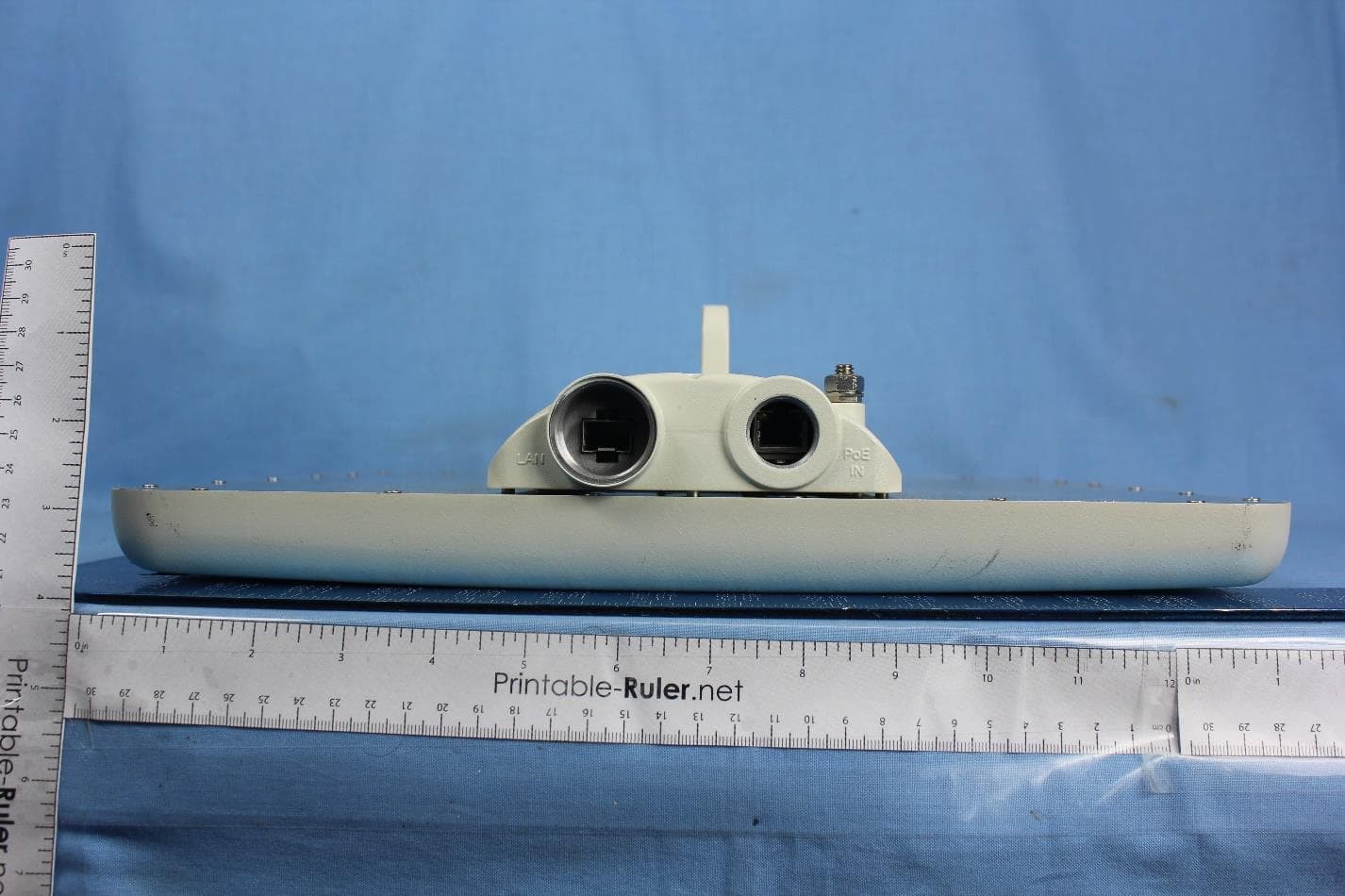
Q3K-PTP5GAX
Feb 25, 20235 GHz High Performance PtP Outdoor Unit
Equipment Class
NII - Unlicensed National Information Infrastructure TX
Q3K-NEO5X
Apr 27, 2021Single Carrier 5.x GHz Base Station with Beamforming Antenna, Dual Carrier 5.x GHz Base Station with Beamforming Antenna
Equipment Class
NII - Unlicensed National Information Infrastructure TX
Q3K-5XSUALMOD
Apr 13, 20215 GHz SU/Alpha Board
Equipment Class
NII - Unlicensed National Information Infrastructure TX
Q3K-5XACMODMS
Sep 13, 20205 GHz MS RF Module
Equipment Class
NII - Unlicensed National Information Infrastructure TX
Q3K-TRBR600G
Aug 25, 2020Point to point/point to multipoint 57-71 GHz radio transceiver
Equipment Class
DXX - Part 15 Low Power Communication Device Transmitter