Q3KRW3XMOD3.6GHz Radio Module for Base and Fixed
Radwin Ltd.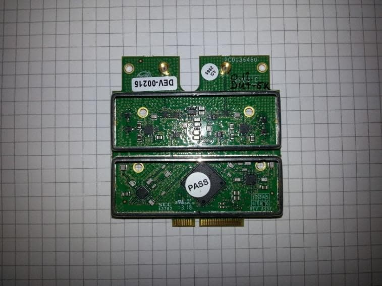
Click to zoom
Application Details
- Equipment Class
- TNB - Licensed Non-Broadcast Station Transmitter
- Date of Grant
- Nov 06, 2013
- Application Purpose
- Original Equipment
- Date of Application
- Nov 05, 2013
- Equipment Note
- 3.6GHz Radio Module for Base and Fixed
- Frequency Range
- 3670.00000000 - 3680.00000000
- Company
- Radwin Ltd.
- Country
- Israel
Documents & Files
Document Text
Text extracted from the exhibit documents filed with the FCC. Open a document above to read the original.
Users Manual
AP0136450 RF Module Operating in the 3.4-3.7 GHz bands REFERENCE GUIDE Regulatory Compliance FCC/IC - Compliance This equipment has been tested and found to comply with the limits for a Class B digital device, pursuant to Part 15 of the FCC Rules and IC RSS standards. These limits are designed to provide reasonable protection against harmful interference in a residential installation. This equipment generates uses and can radiate radio frequency energy and, if not installed and used in accordance with the instructions, may cause harmful interference to radio communications. However, there is no guarantee that interference will not occur in a particular installation. If this equipment does cause harmful interference to radio or television reception, which can be determined by turning the equipment off and on, the user is encouraged to try to correct the interference by one or more of the following measures: • Reorient or relocate the receiving antenna. • Increase the separation between the equipment and receiver. • Connect the equipment into an outlet on a circuit different from that to which the receiver is connected. • Consult the dealer or an experienced radio/TV technician for help. RADWIN Ltd. is not responsible for any radio or communication interference caused by using other than specified or recommended cables and battery or by unauthorized changes or modifications to this equipment. Changes or modifications or modifications not expressly approved by the manufacturer could void the user's authority to operate the equipment. It is the responsibility of the installer to ensure that when using the outdoor antenna kits, only those antennas certified with the product are used. The use of any antenna other than those certified with the product is expressly forbidden by FCC rules 47 CFR part 15.204 and IC RSS standards. Il est de la responsabilité de l'installateur de s'assurer que lorsque vous utilisez les kits d'antennes extérieures, seules les antennes certifiés avec le produit sont utilisés. L'utilisation d'une antenne autre que ceux qui sont certifiés avec le produit est expressément interdite par la réglementation FCC partie 47 CFR 15.204 et IC normes RSS. Outdoor units and antennas should be installed ONLY by experienced installation professionals who are familiar with local building and safety codes and, wherever applicable, are licensed by the appropriate government regulatory authorities. Failure to do so may void the product warranty and may expose the end user or the service provider to legal and financial Caution liabilities. Resellers or distributors of this equipment are not liable for injury, damage or violation of regulations associated with the installation of outdoor units or antennas. The installer should configure the output power level of antennas according to country regulations and antenna type. AP0136450 Reference Guide i Warning Avertissement Les unités extérieures et les antennes doivent être installés que par des professionnels expérimentés d'installation qui sont familiers avec les normes locales et les codes de sécurité et, si applicable, sont agréées par les autorités gouvernementales de réglementation compétents. Ne pas le faire peut annuler la garantie du produit et peuvent exposer l'utilisateur final ou le fournisseur de services d'obligations juridiques et financiers. Revendeurs ou distributeurs de ces équipements ne sont pas responsables des blessures, des dommages ou violation des règlements liés à l'installation des unités extérieures ou des antennes. L'installateur doit configurer le niveau de puissance de sortie des antennes conformément aux réglementations nationales et le type d'antenne. This equipment should be installed and operated with a minimum distance of 57cm between the radiator and your body when operating in the 3.65-3.7 GHz band and 110cm when operating in the 3.45-3.65 GHz band. Warning Cet équipement doit être installé et utilisé à une distance minimale de 57cm entre le radiateur et votre corps lors d'opérations dans la bande de 3.65 à 3.7 GHz et 110cm quand fonctionnant dans la bande de 3,45 à 3,65 GHz The module is granted to operate under FCC/IC certification in the 3.65- 3.70 GHz band and under IC certification in the 3.45-.365 GHz band only. Warning This device complies with Part 15 of the FCC rules and with Industry Canada license- exempt RSS standard(s). Operation is subject to the following two conditions: (1) This device may not cause harmful interference. (2) This device must accept any interference received, including interference that may cause undesired operation. Cet appareil est conforme la norme d'Industrie Canada exempts de licence RSS (s). Son fonctionnement est soumis aux deux conditions suivantes: 1. Cet appareil ne peut pas causer d'interférences, et 2. Cet appareil doit accepter toute interférence, y compris les interférences qui peuvent causer un mauvais fonctionnement de l'appareil. This Class B digital apparatus complies with Canadian ICES-003. Cet appareil numrique de la classe B est conforme la norme NMB-003 du Canada AP0136450 Reference Guide ii Prudence Avertissement Overview The AP0136450 is an RF module operating in the 3.4 – 3.7 GHz frequency bands. It is a TDD OFDM radio supporting 5 MHz, 10 MHz, 20 MHz and 40 MHz channel bandwidths. The RF module cannot work as a stand-alone device. It can operate and be controlled only when attached to a digital main board and altogether assembled in an enclosure suitable for outdoor use. The assembly of the RF module attached to the digital main board is hereafter referred to as ‘ODU’. The ODU in its various outdoor enclosures is manufactured by RADWIN. The RF module is certified as a limited modular approval type with the FCC ID: Q3KRW3XMOD and IC: 5100A-RW3XMOD. Condition of Use The AP0136450 RF module is a proprietary radio interface and can only be connected to digital boards manufactured by RADWIN. The ODU resides in an outdoor enclosure also manufactured and …
Text truncated - open the document above for the full version.
Cover Letter(s)
FCC Confidentiality Form October 24, 2013 Federal Communications Commission 7435 Oakland Mills Road Columbia, MD 21046 Gentlemen: This letter is to comply with Section 0.457 and 0.459 pertaining to confidential material. Radwin Ltd. would like the following documents regarding this submission for FCC ID: Q3KRW3XMOD to be kept confidential. 1) Block Diagram 2) Schematics 3) Bill of Material 4) Tune up procedure The above material contains trade secrets and technical data, which would customarily be guarded from competitors. RADWIN Ltd. would not want them to be accessible to the general public. The product is an RF module assembled inside outdoor enclosures mounted on top of large towers and mounting poles and serviceable only by the licensee or his designated technicians. . Sincerely, Roni Barshan RF Department Manager RADWIN Ltd. RADWIN Ltd. 27 Habarzel St Tel-Aviv, 69710, Israel, Tel- 972-3-766-2900, Fax-972-3-766-2902
Cover Letter(s)
Letter of Authorization Company: RADWIN Ltd. Address: 27 Habarzel St Tel-Aviv, 6971039, Israel Product Name: 3.6 GHz Radio Module Model Number: AP0136450 We authorize MiCOM Labs, 440 Boulder Court, Suite 200, Pleasanton, CA 94566, USA, to act on our behalf on all matters concerning the above named equipment. Any individual within MiCOM Labs is authorized to act on our behalf and take action on the application. This shall include the following: Approval applications (includes complete product documentation package, including Confidential information) and procedures Payment of approval fees We declare that MiCOM Labs, 440 Boulder Court, Suite 200, Pleasanton, CA 94566, USA, is allowed to forward all information related to the approval project to the applied notified body and to the notification entities and to discuss any issues concerning the approval application. Any and all acts carried out by MiCOM Labs on our behalf shall have the same effect as acts of our own. Name: Roni Barshan Date: November 1, 2013 Title: RF Department Manager Signature of applicant:
Cover Letter(s)
www.radwin.com Address goes here Address goes here Address goes here Modular Approval Request Letter To: Federal Communications Commission Equipment Authorization Branch 7435 Oakland Mills Road Columbia, MD 21046 To: Industry Canada Certification and Engineering Bureau 3701 Carling Avenue Bldg. 94 P.O. Box 11490, Station “H” Ottawa, Ontario K2H 8S2 CANADA RE: Limited Modular Approval Request Dear certification officers, Pursuant to the FCC Rule 15.212 Modular transmitters and KDB 966369 D01 Module Certification Guide v01r03, RADWIN Ltd. herby applies for Limited Modular Approval for the Model AP0136450, under FCC ID: Q3KRW3XMOD and IC: 5100A-RW3XMOD. The justification for the application is based on the attestation that RADWIN Ltd., being the sole manufacturer and the assembling factory of both the module and the final product, has full control over the production line and the final product. The module is assembled in enclosures manufactured and tested by RADWIN or its approved subcontractors. The module will not be marketed, distributed or sold to the general public as it is incapable of operating as a standalone product. It is installed only in devices manufactured by RADWIN Ltd. or its approved subcontractors. According to the requirements in section 15.212 of FCC rules - 1. The module has its own RF shielding as shown in the presented in the photo at the end of this document. 2. The module has buffered data/modulation inputs provided by the Atheros. 3. The module has on board the power supply regulation. 4. The module is supplied with unique antenna connector. The module is installed into the device at RADWIN’s production line with the unique antenna cabling and connectors, as tested. Only the RADWIN antennas detailed in the manual are marketed with the module. The final installation of the unit is done only by professional installers trained by RADWIN representatives. 5. The unit was tested in a stand-alone configuration. The test was performed with the module attached to a digital board representing typical RADWIN host configuration. www.radwin.com Address goes here Address goes here Address goes here 6. The module will be labeled with the FCC ID: Q3KRW3XMOD and IC: 5100A-RW3XMOD as shown in the photo at the end of this document. The device into which the module is installed will also display a label referring to the enclosed module as shown at the end of this document: “Contains FCC ID: Q3KRW3XMOD, Contains IC: 5100A-RW3XMOD”. 7. The module was tested for compliance with FCC rule Part 90 subpart Z. The integration of the module is done by RADWIN and there is no access to RADWIN manufactured device by third party. 8. The module complies with RF exposure requirements as shown in the MPE document. Photographs Module with the RF shielding and Label External Label sample attached to host enclosure Roni Barshan November 1, 2013 RF Department Manager RADWIN Ltd.
External Photos
PHOTOGRAPHS Photo #1: Front Photo #2: Front without shielding Photo #3: Rear
ID Label/Location Info
LABELS AND LABEL LOCATION Photo #1: Label on RF Module Photo #2: Label of RW2000/5000 and SU2 Outdoor Units Photo #3: Label on RW2000/5000 ODU Photo #4: Label on RW2000/5000 SU2 ODU Photo #5: Label of RW6000 Outdoor Units Photo #6: Label on RW6000 ODU
Internal Photos
PHOTOGRAPHS Photo #1: Front Photo #2: Front without shielding Photo #3: Rear
RF Exposure Info
Maximum Exposure Limit According to FCC § 90.1335, part 1, § 1.1307(b) Power density limit in 3650 – 3700 MHz band for general population/uncontrolled exposure is 1(mW/cm 2 ). The power density calculation is S = (Pt / 4π r 2 ). Where: Pt – The transmitted power (EIRP) (mW) r – The distance from the unit (cm). The 1(mW/cm 2 ) limit can be calculated from the above based on the following data: Pt – the maximum allowed transmitted EIRP = 46.1 dBm = 40738 mW. Maximum allowed RF safety distance "r", where RF exposure limit may not be exceeded = SQRT(40738/4π) and is more than 57 cm from antenna main lobe. Sincerely, Roni Barshan RF Department Manager RADWIN Ltd. RADWIN Ltd. 27 Habarzel St Tel-Aviv, 6971039, Israel, Tel- 972-3-766-2900, Fax-972-3-766-2902
Test Report
Test Report No. 9312329195 For Radwin Ltd Equipment Under Test: 3.6 GHz Transceiver. Radio module AP0136450 From The Standards Institution Of Israel Industry Division Electronics & Telematics Laboratory EMC Branch Test report No: 9312329195 Page 2 of 70 Pages Title: 3.6 GHz Transceiver. Model: Radio module AP0136450 FCC ID: Q3KRW3XMOD/ IC: 5100A-RW3XMOD Table of Contents 1. Applicant information ................................................................................................... 3 2. Test performance .......................................................................................................... 3 3. Summary of test: ........................................................................................................... 4 4. Equipment under test description ............................................................................... 5 4.1. General description. ................................................................................................... 5 4.2. EUT and test setup block diagrams. ......................................................................... 6 5. Test results: ................................................................................................................... 8 5.1. Transmitter characteristics. ........................................................................................... 8 5.1.1.Emission bandwidth and power limitation according to §§ 90.321, 2.1049. ..................8 5.1.2EIRP output power test § 90.1321(a) .............................................................................13 5.1.3Peak EIRP power density test § 90.1321(a)...................................................................22 5.1.4.Spurious and band edge emission conducted § 90.1323, RSS -197 section 5.7 ...........31 5.1.5.Radiated emissions test according to §§ 90.1323, 2.1053, RSS-197. ...........................44 5.1.6.Frequency stability test according to § 2.1055, RSS-197 section 5.3 ...........................57 6. Receiver characteristics test. .................................................................................... 58 6.1. Receiver spurious emissions test at antenna terminal according to RSS -197 section 5.8 .................................................................................................................. 58 6.2. Receiver spurious emissions radiated according to RSS -197 section 5.8 ........ 60 7. APPENDIX A Photographs and additional information. ......................................... 62 8. APPENDIX B Test equipment used ........................................................................... 65 9. APPENDIX C Abbreviations and acronyms .............................................................. 70 Test report No: 9312329195 Page 3 of 70 Pages Title: 3.6 GHz Transceiver. Model: Radio module AP0136450 FCC ID: Q3KRW3XMOD/ IC: 5100A-RW3XMOD 1. Applicant information Order placed by: Radwin Ltd Address: 27 Habarzel str, Tel-Aviv, 6971039, Israel Sample for test selected by: The customer The date of test: August 2013 Equipment under test information Description of Equipment Under Test (EUT ): 3.6 GHz Transceiver. Model: Radio module AP0136450 Serial Number: NA Manufactured by: Radwin Ltd. 2. Test performance Location: SII EMC Branch Purpose of test: Apparatus compliance verification in accordance with emission requirements Test specifications: 47CFR part 90Z, part 2 §§ 2.1049, 2.1055, part 1 §1.1310 , IC RSS – 197. This Test Report contains 70 pages and may be used only in full. This Test Report applies only to the specimen tested and may not be applied to other specimens of the same product. Test report No: 9312329195 Page 4 of 70 Pages Title: 3.6 GHz Transceiver. Model: Radio module AP0136450 FCC ID: Q3KRW3XMOD/ IC: 5100A-RW3XMOD 3. Summary of test: The EUT was found to be in compliance with requirements of: 47CFR part 90 §§ 90.1321, 90.1323 part 2 and IC RSS – 197. Parameter Subclasses Transmitter characteristics Emission bandwidth 2.1049, IC RSS-197 sec. 5.2 EIRP band power 90.1321(a)/RSS- 197 sec. 5.6 Peak EIRP power density 90.1321(a)/ /RSS- 197 sec. 5.6 Spurious emissions at antenna terminal 90.1323//RSS- 197 sec. 5.7 Spurious emissions radiated 90.1323/RSS- 197 sec. 5.7 Frequency stability test 2.1055/RSS- 197 sec. 5.3 Receiver spurious emissions at antenna terminal. RSS – 197 section 5.8 Receiver spurious emissions radiated. RSS – 197 section 5.8 Electronics & Telematics Laboratory October 2013 Name: Eng. Yuri Rozenberg Name: Michael Feldman Position: Head of EMC Branch Position: Test Technician Measurement uncertainty. Were relevant, the following measurement uncertainty level have been estimated for tests performed on the EUT as specified in CISPR 16-4-2: This uncertainty represents an expended uncertainty expressed at approximately the 95% confidence level using a coverage factor of k=2. Test description Expanded uncertainty Radiated emissions in the open field test site at 3 m measuring distance: 30 MHz – 1.0 GHz 1.0 GHz – 18 GHz 2 Uc (E) = 4.32 dB 2 Uc (E) = 4.47 dB Test report No: 9312329195 Page 5 of 70 Pages Title: 3.6 GHz Transceiver. Model: Radio module AP0136450 FCC ID: Q3KRW3XMOD/ IC: 5100A-RW3XMOD 4. Equipment under test description *The customer provided description. 4.1. General description. The AP0136450 module is a Point to Point /Point to Multipoint 2x2 MIMO high power transceiver designed for various outdoor enclosures manufactured and assembled by RADWIN Ltd. The EUT operates in 5, 10, 20, 40 MHz channel bandwidths in the frequency range 3650- 3700 MHz complying FCC and IC regulations. It is using OFDM transmission technique in TDD duplexing method. The power is provided through the digital board and is internally regulated. The external power to the ODU is provided by a PoE adaptor or indoor unit. The EUT support various types of cross-polarized antennas connected through the N-Type connectors or directly to SMA interface. EUT technical characterist…
Text truncated - open the document above for the full version.
Contact Information
Applicant
Shlomo Weiss(Standardization Officer)
Technical Contact
Test Firm
Israel Testing LaboratoriesIIan Cohen
Technical Specifications
| # | Rule Parts | Frequency Range | Power Output | Emission | Tolerance |
|---|---|---|---|---|---|
| 4 | 9 | 3.67 GHz - 3.68 GHz | 330.00 mW | 40M0W7W | 3.5 ppm |
Other Applications from Radwin Ltd.
Q3K-PTP5GAX
Feb 25, 20235 GHz High Performance PtP Outdoor Unit
Equipment Class
NII - Unlicensed National Information Infrastructure TX
Q3K-NEO5X
Apr 27, 2021Single Carrier 5.x GHz Base Station with Beamforming Antenna, Dual Carrier 5.x GHz Base Station with Beamforming Antenna
Equipment Class
NII - Unlicensed National Information Infrastructure TX
Q3K-5XSUALMOD
Apr 13, 20215 GHz SU/Alpha Board
Equipment Class
NII - Unlicensed National Information Infrastructure TX
Q3K-5XACMODMS
Sep 13, 20205 GHz MS RF Module
Equipment Class
NII - Unlicensed National Information Infrastructure TX
Q3K-TRBR600G
Aug 25, 2020Point to point/point to multipoint 57-71 GHz radio transceiver
Equipment Class
DXX - Part 15 Low Power Communication Device Transmitter