Q3KWINLINKPoint to Point Wireless TX
Radwin Ltd.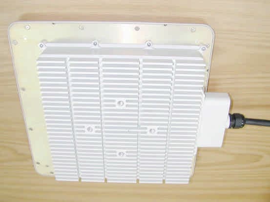
Click to zoom
Application Details
- Equipment Class
- DTS - Digital Transmission System
- Date of Grant
- Jul 10, 2003
- Application Purpose
- Original Equipment
- Date of Application
- Jul 10, 2003
- Equipment Note
- Point to Point Wireless TX
- Frequency Range
- 5730.00000000 - 5840.00000000
- Company
- Radwin Ltd.
- Country
- Israel
Documents & Files
Document Text
Text extracted from the exhibit documents filed with the FCC. Open a document above to read the original.
Users Manual
AirMux-104/ WinLink 582 Installation and Operation Manual Point-to-Point Wireless TDM/IP Multiplexer AirMux-104/ WinLink 582 Point-to-Point Wireless TDM/IP Multiplexer Installation and Operation Manual Notice This manual contains information that is proprietary to RAD Data Communications Ltd. ("RAD") and RADWIN Ltd. (“RADWIN”). No part of this publication may be reproduced in any form whatsoever without prior written approval by RAD Data Communications and RADWIN. Right, title and interest, all information, copyrights, patents, know-how, trade secrets and other intellectual property or other proprietary rights relating to this manual and to the AirMux-104/WinLink 582 and any software components contained therein are proprietary products of RAD and RADWIN protected under international copyright law and shall be and remain solely with RAD and RADWIN. AirMux-104/WinLink 582 is a registered trademark of RAD and RADWIN. No right, license, or interest to such trademark is granted hereunder, and you agree that no such right, license, or interest shall be asserted by you with respect to such trademark. You shall not copy, reverse compile or reverse assemble all or any portion of the Manual or the AirMux-104/WinLink 582. You are prohibited from, and shall not, directly or indirectly, develop, market, distribute, license, or sell any product that supports substantially similar functionality as the AirMux-104/WinLink 582, based on or derived in any way from the AirMux-104/WinLink 582. Your undertaking in this paragraph shall survive the termination of this Agreement. This Agreement is effective upon your opening of the AirMux-104/WinLink 582 package and shall continue until terminated. RAD and RADWIN may terminate this Agreement upon the breach by you of any term hereof. Upon such termination by RAD, you agree to return to RAD and RADWIN the AirMux-104/WinLink 582 and all copies and portions thereof. For further information contact RAD at the address below or contact your local distributor. RAD Data Communications Ltd. 24 Raoul Wallenberg St. Tel Aviv 69719 Israel Tel: 972-3-6458181 Fax: 972-3-6498250 E-mail: [email protected] RADWIN Ltd. 34 Habarzel St, Tel-Aviv 69710, Israel E-mail: [email protected] © 2002–2003 RAD Data Communications Ltd., RADWIN Ltd. Publication No. 193-200-xx/03 General Safety Instructions The following instructions serve as a general guide for the safe installation and operation of telecommunications products. Additional instructions, if applicable, are included inside the manual. Safety Symbols This symbol may appear on the equipment or in the text. It indicates potential safety hazards regarding product operation or maintenance to operator or service personnel. Danger of electric shock! Avoid any contact with the marked surface while the product is energized or connected to outdoor telecommunication lines. . Protective earth: the marked lug or terminal should be connected to the building protective earth bus. Some products may be equipped with a laser diode. In such cases, a label with the laser class and other warnings as applicable will be attached near the optical transmitter. The laser warning symbol may be also attached. Please observe the following precautions: • Before turning on the equipment, make sure that the fiber optic cable is intact and is connected to the transmitter. • Do not attempt to adjust the laser drive current. • Do not use broken or unterminated fiber-optic cables/connectors or look straight at the laser beam. • The use of optical devices with the equipment will increase eye hazard. • Use of controls, adjustments or performing procedures other than those specified herein, may result in hazardous radiation exposure. ATTENTION: The laser beam may be invisible! Always observe standard safety precautions during installation, operation and maintenance of this product. Only qualified and authorized service personnel should carry out adjustment, maintenance or repairs to this product. No installation, adjustment, maintenance or repairs should be performed by either the operator or the user. Warning Warning Handling Energized Products General Safety Practices Do not touch or tamper with the power supply when the power cord is connected. Line voltages may be present inside certain products even when the power switch (if installed) is in the OFF position or a fuse is blown. For DC-powered products, although the voltages levels are usually not hazardous, energy hazards may still exist. Before working on equipment connected to power lines or telecommunication lines, remove jewelry or any other metallic object that may come into contact with energized parts. Unless otherwise specified, all products are intended to be grounded during normal use. Grounding is provided by connecting the mains plug to a wall socket with a protective earth terminal. If an earth lug is provided on the product, it should be connected to the protective earth at all times, by a wire with a diameter of 18 AWG or wider. Rack-mounted equipment should be mounted only in earthed racks and cabinets. Always make the ground connection first and disconnect it last. Do not connect telecommunication cables to ungrounded equipment. Make sure that all other cables are disconnected before disconnecting the ground. Connection of AC Mains Make sure that the electrical installation complies with local codes. Always connect the AC plug to a wall socket with a protective ground. The maximum permissible current capability of the branch distribution circuit that supplies power to the product is 16A. The circuit breaker in the building installation should have high breaking capacity and must operate at short-circuit current exceeding 35A. Always connect the power cord first to the equipment and then to the wall socket. If a power switch is provided in the equipment, set it to the OFF position. If the power cord cannot be readily disconnected in case of emergency, make sure that a readily accessible circuit break…
Text truncated - open the document above for the full version.
Block Diagram
BPF (2 POLES) M P A L N A BPF (3 POLES) L N A MIX RF A M P ATT. A M P BPF (3 POLES) MIX RF ATT. A M P ATT. IF TX 5.8GHz RF CARD Block Diagram ATT.IF IF RX optional short AMP LO AMP LO S P L I T T E R A M P HPF DOUBLE R SYN.SW LO = 2363 - 2425 MHz 15.4.03 1000 MHz 1000 MHz 4726 - 4850 MHz 5726 - 5850 MHz
Cover Letter(s)
FCC Letter of Authorization 15-Apr-2003 To whom it may concern: We the undersigned, hereby authorize Hermon Laboratories to act on our behalf in all manners relating to application for equipment authorization, including signing of all documents relating to these matters. Any and all acts carried out by Hermon Laboratories, on our behalf shall have the same affect as acts of our own. This authorization is valid until further written notice from Radwin Ltd. Sincerely, Erez Zelikovitz V.P. R&D
Cover Letter(s)
June 18, 2003 American TCB 6731 Whittier Ave Suite C110 McLean, VA 22101 USA Subject: Request for confidentiality for a wireless point–to-point multiplexer, model WinLink 582, FCC ID:Q3KWINLINK Dear Gentlemen, We apply to you with request to withhold Radwin Ltd. trade secrets in Application for Certification for FCC ID:Q3KWINLINK. These trade secrets can be found in the transmitter schematic diagram (4 pages of this Application). Many thanks in advance. Sincerely yours, David Ben-Chaim Radio group manager Radwin Ltd
Cover Letter(s)
American Telecommunications Certification Body Inc. 6731 Whittier Ave, McLean, VA 22101 June 22, 2003 RE: Radwin Ltd. FCC ID: Q3KWINLINK After a review of the submitted information, I have a few comments on the above referenced Application. 1) Page 5 of the test report states that the device contains a standard connector and must be professionally installed. However the device appears to contain an integral antenna and the internal connections also appears to contain a non-standard connector. Please explain. Note that a cover letter justifying professional installation has not been provided and may not be necessary. 2) Section 3.2 of the test report states that the shield was not connected between the indoor and outdoor units. Is this typical installation? Please explain why this was not connected and the significance of how it affects any results. 3) UNII measurements made in section 4.6 of the test report appear to use a VBW of 1 kHz which is deemed an average measurement. Note that 15.407(b) stipulates that this is a peak measurement. A VBW of >= 1 MHz should be used. 4) The emissions given in section 4.7 of the report appear to use a VBW of 300 Hz for AVG emissions. However, the UNII report discusses that 1/T must be 1 kHz. Therefore for AVG measurements the VBW should be >= 1 kHz. 5) Information regarding 15.407(g) does not appear to have been provide. Please provide. 6) FYI...It appears that some of the data given in 4.6 and 4.7 may not meet the limits for UNII equipment once measured using the settings given above. Please note that although this device is being requested to be certified under 15.247 (DTS) and 15.407 (UNII), it is not mandatory to show compliance with both. You may select to certify to one section of the rules, or both if you wish. If you select to only certify to DTS rules, please note that a few corrections may be necessary to the marketing material and/or manual. Timothy R. Johnson Examining Engineer mailto: [email protected] The items indicated above must be submitted before processing can continue on the above referenced application. Failure to provide the requested information may result in application termination. Correspondence should be considered part of the permanent submission and may be viewed from the Internet after a Grant of Equipment Authorization is issued. Please do not respond to this correspondence using the email reply button. In order for your response to be processed expeditiously, you must submit your documents through the AmericanTCB.com website. Also, please note that partial responses increase processing time and should not be submitted. Any questions about the content of this correspondence should be directed to the sender.
Cover Letter(s)
American Telecommunications Certification Body Inc. 6731 Whittier Ave, McLean, VA 22101 June 22, 2003 RE: Radwin Ltd. FCC ID: Q3KWINLINK After a review of the submitted information, I have a few comments on the above referenced Application. 1) The reference to 15.35 of the rules regarding averaging "over one complete pulse train, including blanking intervals" is relevant to arrive at a duty cycle when using mathematical techniques for pulsed emissions (ie. OOK modulation, etc). However, when using a spectrum analyzer to make average measurements (as given in section of 4.7 of this report for some measurements) the VBW must be set to >= 1/T, T being the Transmitter on time. This is the same requirement as for measuring the power as shown in method 3 for measuring power given in the DA 02-2138 Public Notice regarding UNII measurements. Note that you may apply a correction factor of 20 log (1.6430/3.3258) = -6.1 to the Peak or Average measurement assuming this is the maximum TX duty cycle in a 100 msec period of time and the average measurements was made correctly. Please confirm if this is the worse case duty cycle for a 100 msec period of time. However the Average measurement must be made with VBW >= 1/T regardless of whether this correction is applied or not. Careful review of all measurements in section 4.7 shows that about 1/2 the measurements were made with 300 Hz, the other half using 1 kHz. The 1 kHz measurements are considered acceptable. Using the assumed -6.1 dB correction factor and looking at the peak reading for the few measurements made with 300 Hz shows that most readings are compliant without taking average measurements However further measurements using a VBW of >= 1 kHz will be required for the following to show compliance: a) 4810 MHz for a carrier frequency of 5810 MHz. b) Note 1: If the maximum duty cycle given above is not considered correct, further measurements may be necessary c) Note 2: plot A58 does not show the Average plot for its measurement. If this was made using 300 Hz it will also be required to be remeasured using a VBW >= 1 kHz. Timothy R. Johnson Examining Engineer mailto: [email protected] The items indicated above must be submitted before processing can continue on the above referenced application. Failure to provide the requested information may result in application termination. Correspondence should be considered part of the permanent submission and may be viewed from the Internet after a Grant of Equipment Authorization is issued. Please do not respond to this correspondence using the email reply button. In order for your response to be processed expeditiously, you must submit your documents through the AmericanTCB.com website. Also, please note that partial responses increase processing time and should not be submitted. Any questions about the content of this correspondence should be directed to the sender.
Cover Letter(s)
HERMON LABORATORIES July 6, 2003 American TCB 6731 Whittier Ave Suite C110 McLean, VA 22101 Attn: Mr. T. Johnson, Examining Engineer RE: your e-mail dated July 3, 2003; Radwin Ltd. FCC ID: Q3KWINLINK, ATCB000524 Dear Mr. Johnson, Please find below the answers to your questions. 1. The antenna is an integral part of the WinLink 582 outdoor radio terminal (RT). Radwin assembles the antenna that has a MCX connector-male on coax cable edge to the connector - female on the PCB of the RT. The MCX connector is a standard connector, but not accessible for a user. 2. Yes, the equipment was tested in typical installation with a typical cable provided by the manufacturer. 3. Please refer to the attached procedures (document “U-NII Part 15, subpart E” – pages 6, 7; Appendix A of the DA 02-2138 Public Notice, page 2, method #3). We are not aware of any other FCC procedures for this measurement. 4. Radiated emissions which fall in the restricted bands per §15.205 were measured for compliance with FCC §15.209(a) limits in accordance with FCC §15.209(e) and §15.35, which require averaging “over one complete pulse train, including blanking intervals” [refer to §15.35(c)]. As a transmission period is 3.3258 msec, video bandwidth was equal or wider than 300 Hz for restricted bands only. 5. Sorry, the information regarding §15.407(g) was omitted. Please find the manufacturer statement below: The frequency stability is maintained within ± 20 ppm by VCTCXO (voltage control temperature compensated crystal oscillator) as a reference oscillator. 6. Radwin Ltd. would like to certify WinLink 582 under both §15.247 and §15.407 as it has been requested. Many thanks for your support and patience. Sincerely, Marina Cherniavsky, certification engineer Hermon Laboratories
Cover Letter(s)
PUBLIC NOTICE Federal Communications Commission 445 12 th St., S.W. Washington, D.C. 20554 News Media Information 202 / 418-0500 Internet: http://www.fcc.gov TTY: 1-888-835-5322 DA 02-2138 August 30, 2002 Measurement Procedure Updated for Peak Transmit Power in the Unlicensed National Information Infrastructure (U-NII) Bands This notice announces an update to the measurement procedures for U-NII devices that are used to determine compliance with the FCC’s technical rules. These changes will better accommodate recent developments in U-NII transmission technologies. The current U-NII rules define “Peak Transmit Power” as “the maximum transmit power as measured over an interval of time of at most 30/B seconds or the transmission pulse duration of the device, whichever is less, under all conditions of modulation”, where B is the 26-dB emission bandwidth of the signal. The rules were intended to permit averaging of peak transmit power over multiple symbols. However, for new multi-carrier technologies, a 30/B averaging interval may not be sufficient for averaging across multiple symbols. For example, an IEEE 802.11(a) signal has a symbol duration of four microseconds, but can have an emission bandwidth of 35 MHz, leading to an upper limit on averaging time of 30/B = 0.86 microseconds. Hence, averaging is performed over less than a single symbol. To accommodate this new technology peak transmit power may be averaged across symbols over an interval of time equal to the transmission pulse duration of the device or over successive pulses. The averaging must include only time intervals during which the transmitter is operating at its maximum power level and must not include any time intervals during which the transmitter is off or is transmitting at a reduced power level. Appendix A describes acceptable measurement procedures under this interpretation. Though not required, provision of a continuous transmit mode on devices to be tested will simplify the measurement process. Where possible, averaging may be performed by trace averaging. When signal characteristics (short pulse widths and wide emission bandwidths) preclude the use of trace averaging, averaging may be implemented by means of a “video filter” in the spectrum analyzer, as described in the appendix. The appendix also includes procedures for measurement of emission bandwidth, peak power spectral density, and peak excursion of the modulation envelope. Questions pertaining to this document may be directed to Steve Martin at (301) 362-3052 or via email at [email protected]. APPENDIX A Guidelines for Assessing Unlicensed National Information Infrastructure (U-NII) Devices - Part 15, Subpart E AUGUST 2002 This document provides guidance for determining compliance of U-NII devices under Part 15, Subpart E. It includes: • Acceptable procedures for measuring peak conducted transmit power, peak power spectral density, emission bandwidth, and peak excursion measurement. All operating modes or data rates of a device must satisfy the requirements. ACCEPTABLE PROCEDURES: Peak conducted transmit output power. In the following, “T” is the transmission pulse duration over which the transmitter is on and transmitting at its maximum power control level. Measurements are performed with a spectrum analyzer. Three methods are provided to accommodate measurement limitations of the spectrum analyzer depending on signal parameters. Set resolution bandwidth (RBW) = 1 MHz. Set span to encompass the entire emission bandwidth (EBW) of the signal. Use automatic setting for analyzer sweep time (except in Method #2). Check the sweep time to determine which procedure to use. • If sweep time ≤ T, use Method #1 -- spectral trace averaging -- and sum the power across the band. Note that the hardware operation may be modified to extend the transmission time to achieve this condition for test purposes. (Method #1 may be used only if it results in averaging over intervals during which the transmitter is operating at its maximum power control level; intervals during which the transmitter is off or is transmitting at a reduced power level must not be included in the average.) • If sweep time > T, then the choice of measurement procedure will depend on the EBW of the signal. ◊ If EBW ≤ largest available RBW on the analyzer, use Method #2--zero-span mode with trace averaging--and find the temporal peak. (Method #2 may be used only if it results in averaging over intervals during which the transmitter is operating at its maximum power control level; intervals during which the transmitter is off or is transmitting at a reduced power level must not be included in the average.) ◊ If EBW > largest available RBW, use Method #3--video averaging with max hold--and sum power across the band. Method #1: • Set span to encompass the entire emission bandwidth (EBW) of the signal. • Set RBW = 1 MHz. • Set VBW ≥ 3 MHz. • Use sample detector mode if bin width (i.e., span/number of points in spectrum display) < 0.5 RBW. Otherwise use peak detector mode • Use a video trigger with the trigger level set to enable triggering only on full power pulses. Transmitter must operate at full control power for entire sweep of every sweep. If the device transmits continuously, with no off intervals or reduced power intervals, the trigger may be set to “free run”. • Trace average 100 traces in power averaging mode. • Compute power by integrating the spectrum across the 26 dB EBW of the signal. The integration can be performed using the spectrum analyzer’s band power measurement function with band limits set equal to the EBW band edges or by summing power levels in each 1 MHz band in linear power terms. The 1 MHz band power levels to be summed can be obtained by averaging, in linear power terms, power levels in each frequency bin across the 1 MHz. Method #2: • Set zero span mode. Set center frequency to the midpoint between the -26 dB points of the signal. • Set RBW ≥ EBW. • Set VBW ≥ 3 RBW. [If VBW ≥ 3 RBW is not…
Text truncated - open the document above for the full version.
Cover Letter(s)
Unlicensed National Information Infrastructure Devices (UNII)-Part 15 Subpart E • Test procedures for UNII devices are, as of yet, undetermined. When a “recommended” test procedure is released by the OET Lab, guidance will be provided as to what is considered “acceptable test procedures”. • Acceptable procedures Peak conducted transmit output power. * Method #2 is more accurate than #1 as compared to what is specified for the peak transmit power. Compliance with either method is acceptable. 1) Use a peak power meter. 2) Use an analyzer with RBW greater than emission bandwidth. Use a reduced video filter e.g. VBW = emission bandwidth/30.(Video filter). No video averaging. Use a Peak detector on max hold. * For Broadband emissions where the available analyzer bandwidth is less than emission bandwidth. Set the RBW=1MHz,VBW= 30kHz. You can use a bandwidth correction factor of 10 log (emission BW)/ 1MHz with the 1 MHz capturing the peak of the emission. Use a Peak detector on max hold. Emission Bandwidth “B”MHz. * Use a RBW = 1% of the emission bandwidth. * Set the VBW > RBW * Use a peak detector. * Do not use the Max Hold function. Rather, use the view button to capture the emission. * Measure the widest width of the emission that is 26 dB down from the peak of the emission. Peak power spectral density(PPSD). * Method #3 is more accurate than #1 as compared to what is specified for the PPSD limit. Compliance with either method is acceptable. *Antenna conducted measurement 1) * Use a peak detector on max hold. time of installation, then professional installation of this transmitter is required. The installation manual must contain adequate instructions such that the correct transmit power can be chosen for any antenna being used. Does the measured peak power spectral density, in conjunction with the stated antenna gain, comply with the de facto +40 dBm EIRPsd limit for all proposed antennas to be used solely in point-to-point applications? • Note that the psd limit is reduced in order to comply with the de facto EIRPsd limit. If the measured psd is already below the limit a reduction may not be necessary. Does the proposed point-to-point system meet the appropriate requirements, and do the installation instructions contain the correct language? • Understand the intent behind allowing the EIRP relaxation for point-to-point applications only. • When multiple antennas are listed in the installation manual, those that may only be used in point-to-point applications should be clearly indicated. 15.407(a)(6): Does the ratio of peak modulation envelope excursion to peak transmit power meet the 13 dB/MHz limit? • The comparison between the two measured levels is made within the same 1 MHz segment. 15.407(b)(1)-(3): Were acceptable test procedures and instrument settings used to measure the EIRP of emissions outside of the frequency bands of operation, both within and outside of the passband of all proposed antennas? Do the measured unwanted emission EIRP levels comply with the appropriate limits, as determined by the frequency band of operation and the frequency of the spurious emission, up to 40 GHz, for all proposed antennas? • These limits are on the Effective Isotropic Radiated Transmit Power. The same measurement settings used to measure the transmit power of the fundamental emission may be used here. • Within the passband of the antenna an RF conducted measurement may be made. This level, added to the stated antenna gain for each proposed antenna, must comply with the limit. • Outside of the passband of the antenna a radiated measurement must be made, as the gain of the antenna outside of its passband is uncertain, or, the emission may radiate from the case of the EUT. This measured field strength must then be converted to an equivalent EIRP for comparison to the limit. • It is likely that compliance with the unwanted emission EIRP limit, particularly at the bandedges, will determine the maximum transmit power allowable at bandedge channels for each antenna. The installation manual must make this clear. 15.407(b)(5): Were acceptable test procedures and instrument settings used to measure unwanted radiated emission levels below 1 GHz, and AC line conducted emissions? • Use ANSI C63.4 as a guide. Do the measured unwanted radiated emission levels comply with the Section 15.209 field strength limit? • In order to demonstrate compliance with this particular requirement, measurements may be performed on the highest gain antenna of each “type”. In other words, if multiple yagi, patch, and dish antennas are proposed, only the highest gain yagi, patch, and dish must be tested. • Measurements should also be made on the lowest gain antenna, so that the EUT is operating at its highest available output power, in order to test for case radiation.
Cover Letter(s)
HERM O N LA BO RA TO RIES July 9, 2003 American TCB 6731 Whittier Ave Suite C110 McLean, VA 22101 Attn: Mr. T. Johnson, Examining Engineer RE: your e-mail dated July 8, 2003; Radwin Ltd. FCC ID: Q3KWINLINK, ATCB000524 Dear Mr. Johnson, Please find below the answers to your questions. a) Please find attached the corrected page 95, Plot A73 with VBW=1 kHz (revised test report RADEMC_FCC.15489-2_rev1). b) Radwin Ltd. confirms that the duty cycle is fixed (so is the maximum), and is like given in the Plot A4, page 26 of the test report. c) Please refer to the Plot A55, page 77 of the test report. Sorry for my mistake – corrected page 18 with reference to Plot A55 in average mode of the revised test report RADEMC_FCC.15489-2_rev1 is attached. Please inform, shall be revised test report RADEMC_FCC.15489-2_rev1 uploaded? Many thanks for your support and patience. Sincerely, Marina Cherniavsky, certification engineer Hermon Laboratories
External Photos
FCC ID:Q3KWINLINK Date: June 2003 Page 1 of 3 EXTERNAL PHOTOGRAPHS This document contains 2 photographs FCC ID:Q3KWINLINK Date: June 2003 Page 2 of 3 Photograph No.1 Winlink 582 outdoor radio terminal Front view FCC ID:Q3KWINLINK Date: June 2003 Page 3 of 3 Photograph No.2 Winlink 582 outdoor radio terminal Rear side view
ID Label/Location Info
An outdoor radio terminal shall bear the label with FCC ID:Q3KWINLINK and RADWIN logo on a side panel as shown in the drawing below: The statement according to FCC part 15 section 15.19 is affixed to indoor unit, connected by wires to outdoor unit and marketed together. WINLINK Manufacturer: Radwin Ltd. This device complies with Part 15 of the FCC Rules. Operation is subject to the following two conditions: (1) This device may not cause harmful interference, and (2) this device must accept any interference received, including interference that may cause undesired operation.
Internal Photos
FCC ID:Q3KWINLINK Date: June 2003 Page 1 of 8 INTERNAL PHOTOGRAPHS This document contains 7 photographs FCC ID:Q3KWINLINK Date: June 2003 Page 2 of 8 Photograph No.1 Winlink 582 outdoor radio terminal Internal view FCC ID:Q3KWINLINK Date: June 2003 Page 3 of 8 Photograph No.2 Winlink 582 outdoor radio terminal RF PCB front view FCC ID:Q3KWINLINK Date: June 2003 Page 4 of 8 Photograph No.3 Winlink 582 outdoor radio terminal RF PCB front view FCC ID:Q3KWINLINK Date: June 2003 Page 5 of 8 Photograph No.4 Winlink 582 outdoor radio terminal RF PCB second side view FCC ID:Q3KWINLINK Date: June 2003 Page 6 of 8 Photograph No.5 Winlink 582 outdoor radio terminal IF and digital PCB front view FCC ID:Q3KWINLINK Date: June 2003 Page 7 of 8 Photograph No.6 Winlink 582 outdoor radio terminal IF and digital PCB front view FCC ID:Q3KWINLINK Date: June 2003 Page 8 of 8 Photograph No.7 Winlink 582 outdoor radio terminal IF and digital PCB second side view
Operational Description
5.8 GHZ MA-WA58-2X 5.8 GHz Subscriber Antenna MA-WA58-2X Mars 5.8 GHz Broadband Antenna provides a cost effective solution for high volume deployments. Additional Features: • Aesthetic, small and unobtrusive profile blends easily with any environment. • DC grounded for lightning protection to meet local electrical building codes. Specifications: Electrical Frequency range 5.725- 5.85 GHz GAIN, min. 20 dBi VSWR, max. 1:1.5 Polarization Liner Vertical 3 dB Beamwidth - Az, typ. 14.5 o 3 dB Beamwidth - El, typ. 11.5 o Cross Polarization 20 dB Power Handling 10 Watts Input Impedance 50 Ohms Front to Back 30 dB Mechanical and Environmental Dimensions (LxWxD) 305x305x30 mm Base Plate Aluminum; Studs location to fit RadWin`s Radio Input/RF Interface MCX Plug with 20 cm Coaxial Cable RG-316 Radome Polycarbonate, UV protected Operating Temperature -45°C to +75°C Lightning Protection DC grounded Service Life >20 years Wind ( Operating ) 150 km/ hr Wind ( Survival ) 200 km/ hr Relative humidity 0 % - 100 % Relative ice load 25 mm Sealing IP - 67 5.8 GHZ MA-WA58-2X Standard Compliance ETSI EN 302 085 V1.1.1 (2000-06) Range 1, TS 1, 2, 3, 4, 5 Environmental Test Standard Low Temperature IEC 68-2-1; 72h; -55ºC High Temperature IEC 68-2-2; 72h; +71ºC Temp. Cycling IEC 68-2-14; 1h; -45ºC+70ºC; 3 Cycles Vibration IEC 60721-3-4; 30 min/axis; Random 4M5 Shock Mechanical IEC 60721-3-4; 4M5 Humidity ETSI EN300-2-4 T4.1E; 144h; 95% Water Tightness IEC 529; IP67 Solar Radiation ASTM G53; 1000h Flammability UL94; Class HB Salt Spray IEC 68-2-11 Ka; 500h Ice and Snow 25 mm Radial Wind Speed Survival Operation 160 Km/h – 220 Km/h
Operational Description
REVISION RECORD REV ECO DESCRIPT…
Text truncated - open the document above for the full version.
Contact Information
Applicant
Shlomo Weiss(Standardization Officer)
Technical Contact
Hermon LaboratoriesEdward Usoskin
[email protected]972 4 628-8001
Harakevet Industrial zone · Binyamina · Israel
Non-Technical Contact
Radwin Ltd.Ron Kapon
[email protected]+972 3645 5584
Test Firm
Hermon Laboratories Ltd.Alexander Usoskin
Technical Specifications
| # | Rule Parts | Frequency Range | Power Output |
|---|---|---|---|
| 1 | 15C | 5.73 GHz - 5.84 GHz | 39.00 mW |
Other Applications from Radwin Ltd.
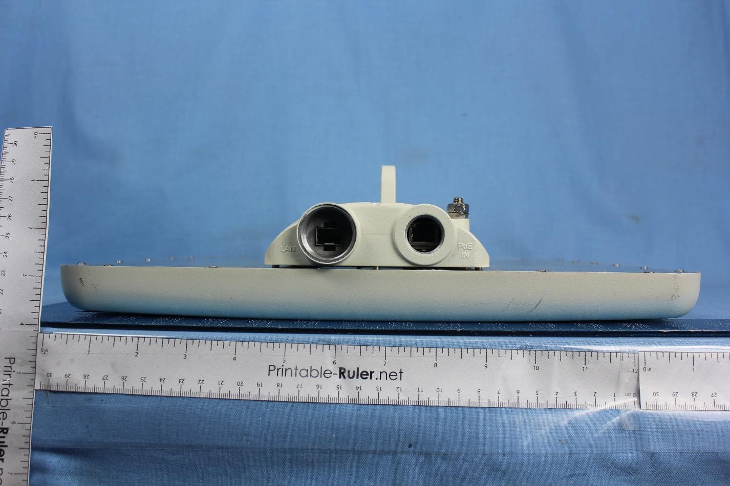
Q3K-PTP5GAX
Feb 25, 20235 GHz High Performance PtP Outdoor Unit
Equipment Class
NII - Unlicensed National Information Infrastructure TX
Q3K-NEO5X
Apr 27, 2021Single Carrier 5.x GHz Base Station with Beamforming Antenna, Dual Carrier 5.x GHz Base Station with Beamforming Antenna
Equipment Class
NII - Unlicensed National Information Infrastructure TX
Q3K-5XSUALMOD
Apr 13, 20215 GHz SU/Alpha Board
Equipment Class
NII - Unlicensed National Information Infrastructure TX
Q3K-5XACMODMS
Sep 13, 20205 GHz MS RF Module
Equipment Class
NII - Unlicensed National Information Infrastructure TX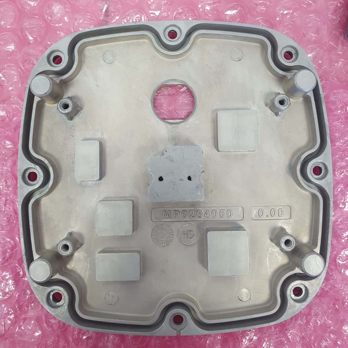
Q3K-TRBR600G
Aug 25, 2020Point to point/point to multipoint 57-71 GHz radio transceiver
Equipment Class
DXX - Part 15 Low Power Communication Device Transmitter