Q6DCTX712AV2802.11b WLAN miniPCI Card
Creatix Polymedia GmbH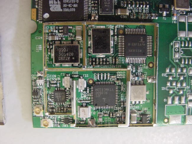
Click to zoom
Application Details
- Equipment Class
- DTS - Digital Transmission System
- Date of Grant
- Jun 25, 2003
- Application Purpose
- Original Equipment
- Date of Application
- Jun 25, 2003
- Equipment Note
- 802.11b WLAN miniPCI Card
- Frequency Range
- 2412.00000000 - 2462.00000000
- Company
- Creatix Polymedia GmbH
- Country
- Germany
Documents & Files
Document Text
Text extracted from the exhibit documents filed with the FCC. Open a document above to read the original.
Users Manual
Installation of the Wireless LAN card CTX 712A After starting the PC, the Wireless LAN card is found as a New Hardware “Network Controller”: Click on „Install from a list or a specific location“ and then „Next>“ Choose the directory where the driver was unzipped and click on „Next>“ The driver files will be copied. Finish the driver installation with a click on the „Finish“ button. Configuration of the Wireless LAN Card: To configure the WLAN Card go to the “Network Connections” < start – control panel > and click on the connection of the “Creatix CTX712 Wireless LAN PCI Card” with the right mouse button to go to the context menu < Properties >. Go to “Wireless Network”. Delete the check mark “Use Windows to configure my wireless network settings” to use the configuration file of the card. Configuration file (look at the task bar): Go to “Configuration”. Here you can set your “Network Name” and “Network Type”. In this Window you can set the “WEP encryption”. This Window gives you information about the driver version and the firmware. Deinstallation of the Wireless LAN card CXT 712A Go to the Control Panel “<System – Hardware – Device Manager>”: Click on the icon Creatix CTX712 Wireless LAN PCI Card under Network Adapters and delete this entry. Press the button „OK“ to remove the driver. Go into the hidden directory \Windows\Inf. Check all “oem*.inf” files (they can be opened by double click) to find the oem*.inf file “Prismnic.inf” (Wireless LAN Card): “Delete” this file. After deleting the file shut down your PC to remove the card or restart to install a new update for the driver. Regulatory Statements FCC Certification The United States Federal Communication Commission and the Canadian Department of Communication have established certain rules governing the use of electronic equipment. Part15, Class B This device complies with Part 15 of the FCC Rules. Operation is subject to the following two conditions: (1) This device my not cause harmful interference, and (2) this device must accept any interference received, including interference that may cause undesired operation. This equipment has been tested and found to comply with the limits for a Class B digital device, pursuant to Part 15 of the FCC Rules. These limits are designed to provide reasonable protection against harmful interference in a residential installation. This equipment generates, uses and can radiate radio frequency energy and, if not installed and used in accordance with the instructions, may cause harmful interference to radio communications. However, there is no guarantee that interference will not occur in a particular installation. If this equipment does cause harmful interference to radio or on, the user is encouraged to try to correct the interference by one or more of the following measures: - Reorient or relocate the receiving antenna. - Increase the separation between the equipment and receiver. - Connect the equipment into an outlet on a circuit different from that to which the receiver is connected. - Consult the dealer or an experienced radio/TV technician for help. Caution: 1. 2. 3. This equipment complies with FCC radiation exposure limits set forth for an uncontrolled environment. This equipment should be installed and operated with minimum distance 20cm between the radiator and your body. This transmitter must not be co-located or operating in conjunction with any other antenna or transmitter. Changes or modifications made to this equipment not expressly approved by Creatix Polymedia GmbH may void the FCC authorization to operate this equipment
ID Label/Location Info
Label Location INFO CTX712A V.2 The label is located on the top-side. See the location as below:
Internal Photos
Testreport for digitally modulated TX CETECOM ICT Services GmbH Saarbruecken, Germany Test report No.: 4-1049-01-02/03 Date: 2003-06-23 Page 55 of 56 Testreport for digitally modulated TX CETECOM ICT Services GmbH Saarbruecken, Germany Test report No.: 4-1049-01-02/03 Date: 2003-06-23 Page 56 of 56
Test Report
Recognized by the Federal Communications Commission Anechoic chamber registration no: 90462 (FCC) Anechoic chamber registration no: 3436 (IC) TCB ID: DE 0001 Accredited by the German Accreditation Council DAR–Registration Number TTI–P–G 166/98 Independent ETSI compliance test house ETSI Accredited Bluetooth™ Test Facility (BQTF) Test report no.: 4-1049-01-02/03 FCC Part 15.247 / CANADA RSS-210 FCC ID: Q6DCTX712AV2 CTX 712a V.2 CETECOM – ICT Services GmbH Untertürkheimerstr. 6-10 D-66117 Saarbrücken, Germany Telephone: + 49 (0) 681 / 598-0 Fax: + 49 (0) 681 / 9075 BLUETOOTH is a trademark owned by Bluetooth SIG, Inc. and licensed to Cetecom Testreport for digitally modulated TX CETECOM ICT Services GmbH Saarbruecken, Germany Test report No.: 4-1049-01-02/03 Date: 2003-06-23 Page 2 of 56 Table of contents 1. ADMINISTRATIVE DATA.......................................................................................................................................................3 1.1. ADMINISTRATIVE DATA OF THE TEST FACILITY..................................................................................................................3 1.1.1 Identification of the testing laboratory.......................................................................................................................3 1.1.2 Organizational items.....................................................................................................................................................3 1.1.3 Applicant ́s details..........................................................................................................................................................4 1.2 ADMINISTRATIVE DATA OF MANUFACTURER / MEMBER....................................................................................................4 1.3 DESCRIPTION OF THE EQUIPMENT UNDER TEST (EUT)......................................................................................................5 1.3.1 EUT: Type, S/N etc........................................................................................................................................................5 1.3.2 If RF component testing only, describtion of additional used HW/SW.................................................................5 1.3.3 Additional EUT information...............................................................................................................................5 1.3.4 EUT operating modes....................................................................................................................................................6 1.3.5 Extreme conditions testing values...............................................................................................................................6 3.1 DESCRIPTION OF TEST SET-UP................................................................................................................................................8 3.1.1 Radiated measurements................................................................................................................................................8 3.1.2 Conducted measurements.............................................................................................................................................8 3.3 ADDITIONAL COMMENTS........................................................................................................................................................9 3.4 ANTENNA GAIN........................................................................................................................................................................9 3.5 PEAK POWER SPECTRAL DENSITY (DIGITALLY MODULATED SYSTEMS)§15.247(D)....................................................10 3.9 SPECTRUM BANDWIDTH OF A DSSS SYSTEM / 6 DB BANDWITH §15.247(A2)...........................................................13 3.7 MAXIMUM OUTPUT POWER (CONDUCTED) § 15.247 (B) (1)...........................................................................................17 3.8 MAX. PEAK OUTPUT POWER (RADIATED) § 15.247 (B) (1)..............................................................................................19 3.12 CONDUCTED EMISSIONS §15.247 (C)..................................................................................................................................20 3.10 BAND-EDGE COMPLIANCE OF RADIATED EMISSIONS §15.205.........................................................................................26 3.11 SPURIOUS EMISSIONS - CONDUCTED (TRANSMITTER) § 15.247 (C)..............................................................................30 3.12 SPURIOUS EMISSIONS - RADIATED (TRANSMITTER) § 15.209........................................................................................31 3.13 SPURIOUS EMISSIONS - RADIATED (RECEIVER) § 15. 209...............................................................................................39 3.14 SPURIOUS EMISSIONS - RADIATED <30 MHZ § 15.209....................................................................................................43 3.15 CONDUCTED EMISSIONS <30 MHZ § 15.207.....................................................................................................................44 4 PHOTOGRAPHS.......................................................................................................................................................................49 4.1 TEST SETUP PHOTOS ............................................................................................................................................................49 4.2 EXTERNAL PHOTOS INCL. ACCESSORIES............................................................................................................................51 4.3 INTERNAL PHOTOS ............................................................................................................................................…
Text truncated - open the document above for the full version.
Test Setup Photos
Testreport for digitally modulated TX CETECOM ICT Services GmbH Saarbruecken, Germany Test report No.: 4-1049-01-02/03 Date: 2003-06-23 Page 49 of 56 4 Photographs 4.1 TEST SETUP PHOTOS Testreport for digitally modulated TX CETECOM ICT Services GmbH Saarbruecken, Germany Test report No.: 4-1049-01-02/03 Date: 2003-06-23 Page 50 of 56 Testreport for digitally modulated TX CETECOM ICT Services GmbH Saarbruecken, Germany Test report No.: 4-1049-01-02/03 Date: 2003-06-23 Page 51 of 56 AC-conducted:
Contact Information
Applicant
Frank von Ehren(Product Manager)
[email protected]+49 681 9811 413
Test Firm
Cetecom ICT Services GmbHRalf Hoehn
Technical Specifications
| # | Rule Parts | Frequency Range | Power Output |
|---|---|---|---|
| 1 | 15C | 2.41 GHz - 2.46 GHz | 70.00 mW |
Other Applications from Creatix Polymedia GmbH
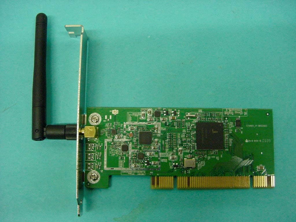
Q6DCTX405
Sep 19, 2004WLAN PCI Card 802.11 b/g
Equipment Class
DTS - Digital Transmission System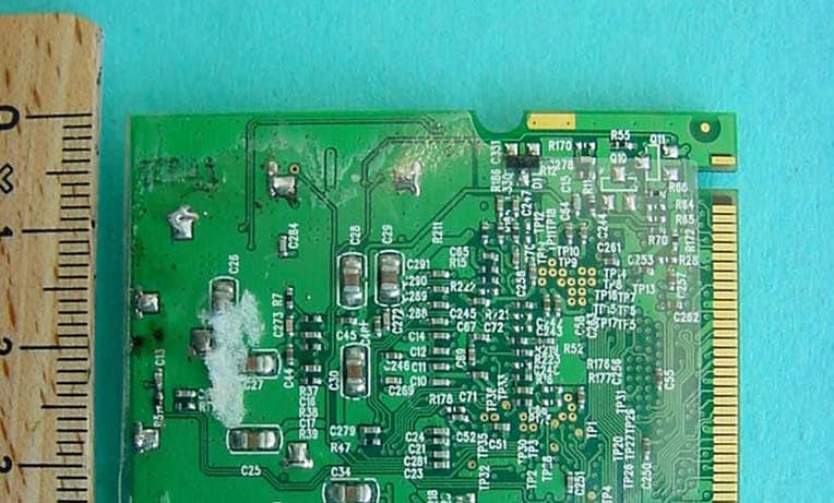
Q6DCTX714
Dec 11, 2003802.11b/g WLAN miniPCI Card
Equipment Class
DTS - Digital Transmission SystemQ6DCTX712V2
Sep 11, 2003802.11b WLAN miniPCI Card
Equipment Class
DTS - Digital Transmission System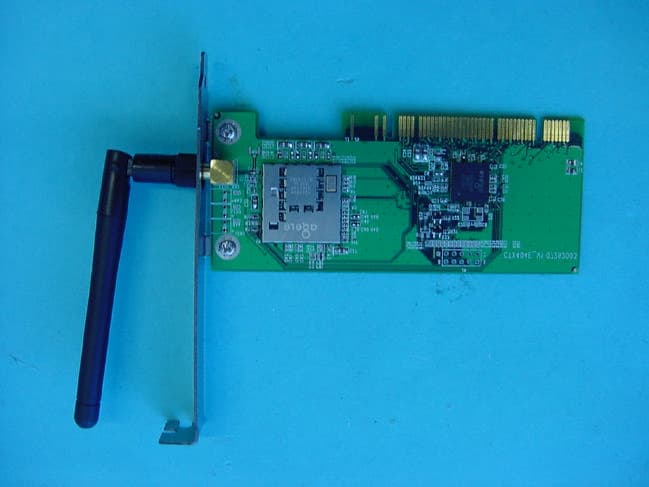
Q6DCTX404EV2
Sep 03, 2003IEEE 802.11B WLAN PCI Card
Equipment Class
DTS - Digital Transmission System